 ?Mathematical formulae have been encoded as MathML and are displayed in this HTML version using MathJax in order to improve their display. Uncheck the box to turn MathJax off. This feature requires Javascript. Click on a formula to zoom.
Abstract
An inversion framework employing a Gauss–Newton method is developed to reconstruct material profiles in heterogeneous, viscoelastic, semi-infinite domains. In particular, a full-waveform inversion approach is investigated to image the elastic and attenuating parameters of a layered media. To account for the viscoelasticity of the medium, a Generalized Maxwell Body with one spring and two Maxwell elements in parallel (GMB2) is adopted in the forward and inverse wave propagation problems. Perfectly-matched-layers were introduced as wave absorbing buffers to simulate the semi-infinite extent of the domain. Using transient wave equations endowed with the GMB2 constitutive relation and the PML, a partial-differential-equations-constrained optimization scheme was implemented that lead to classic KKT (Karush–Kuhn–Tucker) conditions including time-dependent state, adjoint, and time-invariant control problems. An optimal solution of the viscoelastic parameters was obtained using a reduced-space approach based on a line search algorithm where the search direction was computed by the Gauss–Newton method. Considerable improvements on the accuracy and convergence rate of solutions were made by the developed Gauss–Newton inversion procedure compared to previous research using the Fletcher–Reeves method.
1. Introduction
Recently, perfectly-matched-layers (PMLs) have been widely used as wave-absorbing boundaries for elastodynamic wave propagation problems in unbounded domains. Compared to the remarkable progress made for the elastodynamic PML, there has been substantially less development of the PML in viscoelastic media. Among the developments for viscoelastic media is the work by Bécache et al. [Citation1] who adapted the PML to the Zener viscoelastic model and extended a mixed finite element method proposed in [Citation2] for numerical solution. Ma and Liu associated the PML with the intrinsic attenuation parameter and implemented it with an explicit finite element method.[Citation3] They used the coarse-grain approach for modeling
in a structured finite-element mesh.[Citation4] Later, Ely et al. [Citation5] extended the work of [Citation3] by using a generalized finite difference method for viscoelastic wave modeling in 3D heterogeneous media.
An advancing, unsplit-field, convolutional PML was also proposed for 3D viscoelastic seismic wave modeling in the context of a fourth-order staggered finite-difference method.[Citation6] This formulation was particularly useful when two or more standard linear solid mechanisms were used. Dhemaied et al. [Citation7] introduced modeling of seismic wave propagation in viscoelastic media using the auxiliary differential equation method. The formulation was based on a convolutional PML in a homogeneous viscoelastic medium. Based on Carcione’s theory,[Citation8] Yan and Liu [Citation9] presented a two-dimensional first order velocity-stress formulation for viscoelastic, tilted, and transversely isotropic media. They introduced the PML in a viscoelastic media, and used a finite difference scheme with a rotated staggered grid to solve the equations. Most recently, Assimaki et al. [Citation10] demonstrated time-domain forward and inverse modeling of lossy soils in viscoelastic heterogeneous PML-truncated domains. They employed a Generalized Maxwell Body with one spring and two Maxwell elements in parallel (GMB2) as the constitutive model of a viscoelastic medium. Their approach yielded the reconstruction of the GMB2 material properties in a PML-truncated domain via a full-waveform inversion method.
This paper extends the inversion framework of [Citation10] and discusses improvements on the accuracy and convergence rate of solutions in the full-waveform inversion. In particular, it is sought to recover the spatial distribution of the GMB2 material parameters and
from surficial measurements of the domain’s response to interrogating waves via a Gauss–Newton full-waveform inversion method in the time-domain. The reconstructed profiles of
and
can be utilized to construct the profile of the quality factor,
, a commonly used metric of intrinsic and apparent attenuation.
To reconstruct viscoelastic profiles, a partial-differential-equations (PDE) constrained optimization approach is introduced, where an objective functional representing the misfit between measured and computed surficial displacement responses is minimized subject to the satisfaction of a set of viscoelastic wave equations. The PML-endowed wave equations developed in [Citation10] based on the GMB2 constitutive model are used as the constraint in the optimization framework. Specifically, a Lagrangian functional is constructed by augmenting the misfit through the side imposition of the governing PDEs via Lagrange multipliers. Enforcing the stationarity of the Lagrangian leads to KKT (Karush–Kuhn–Tucker) conditions comprising time-dependent state, adjoint, and time-independent control problems. Here, the state and adjoint problems are initial- and final-value problems, respectively, and both are resolved using a mixed finite element method. The optimal solution of material parameters is obtained via a reduced-space approach, where the updates of and
are determined by a Gauss–Newton–Krylov optimization method at each inversion iteration.
In the mixed finite element method, special pairs of basic functions were used to avoid numerical instabilities that may occur when dealing with forward state as well as backward adjoint problems.[Citation11, Citation12] In the implementation of the developed inversion procedure, storage problems due to reverse time backward fields were not prohibitive because of the dimensional simplification to 1D heterogeneous media.
The significance of this research lies on the fact that the use of PML in conjunction with the Gauss–Newton–Krylov method can be one of the best solution strategies possible for the inversion of viscoelastic properties in semi-infinite domains in terms of the accuracy and convergence of solutions. Through a series of numerical examples, it is reported that substantial improvements on the accuracy and convergence rate of solutions were attained by the developed inversion procedure, compared to the results of [Citation10] where the Fletcher–Reeves method was used.
2. Forward problem
The forward problem is posed in a horizontally layered, vertically heterogeneous viscoelastic solid medium of semi-infinite extent as depicted in Figure (a). The forward problem of interest herein is to determine compressional wave motion in such a layered medium due to a stress load applied on the surface. The problem can be reduced to a one-dimensional problem in the direction of the wave propagation. To simulate the wave motion in the semi-infinite extent, the semi-infinite domain is truncated and a PML wave-absorbing boundary is introduced beyond the truncation surface, as shown in Figure (b). Figure (c) shows the schematic of a PML-truncated finite computational domain comprising the regular domain (
) and the PML (
).
Figure 1. (a) Original domain: horizontally-layered heterogeneous semi-infinite solid medium; (b) PML-truncated domain; (c) One-dimensional schematic of the PML-truncated domain (PML location: ).
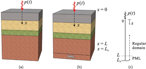
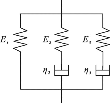
In recent work, Assimaki et al. [Citation10] discussed the constitutive model of a reduced Generalized Maxwell Body (GMB2) that can effectively capture the frequency-independence of . The model consists of three elastic springs (
) and two dashpots (
) in such a way that one spring and two Maxwell elements are connected in parallel, as shown in Figure . For the two Maxwell elements, relaxation time parameters
and
were defined as:
(1)
(1)
where and
can be shown to be constants within a certain frequency range.[Citation4, Citation10] For the three moduli of the GMB2, it was shown that:
(2)
(2)
(3)
(3)
where and
are constants. Equations (Equation2
(2)
(2) ) and (Equation3
(3)
(3) ) show that the Generalized Maxwell Body depicted in Figure can be described by any of the pairs (
), (
,
), or (
,
). If
and
are taken as two independent material parameters, the damping coefficients
and
can be obtained from (Equation1
(1)
(1) ) as
and
, respectively. Based on the GMB2 constitutive model, Assimaki et al. showed that viscoelastic wave motion in PML-truncated solid domains can be described by a system of coupled PDEs in the time-domain.[Citation10] The governing PDEs are adopted herein to establish the forward problem in one-dimensional viscoelastic solid domains truncated by the PML. The problem can be stated as: find
and
, such that:
(4a)
(4a)
(4b)
(4b)
(4c)
(4c) and
(5a)
(5a)
(5b)
(5b)
(5c)
(5c)
(5d)
(5d) where
denotes location and
denotes time. In the above,
,
, and
denote displacement, stress, and mass density, respectively, and
is an auxiliary stress-memory term. Additionally,
is defined as
, where
is a reference wave velocity of the medium and
is a function that plays a central role in artificial wave attenuation within the PML. The attenuation function
was defined in [Citation11] as:
(6)
(6)
in which is the length of the PML and
is a user-tunable reflection coefficient that controls the amount of reflection from the fixed PML end
. In Equation (Equation4b
(4b)
(4b) ), the coefficients
are auxiliary variables in terms of
, relaxation times, and the two material parameters
and
of the GMB2 constitutive model. They are expressed as:
(7)
(7)
(8)
(8)
(9)
(9)
(10)
(10)
Equations (Equation4a(4a)
(4a) ) and (Equation4b
(4b)
(4b) ) are the displacement (
)-stress (
) mixed equations governing the propagation of waves in one-dimensional viscoelastic PML-truncated domains. Equations (Equation5a
(5a)
(5a) ) and (Equation5b
(5b)
(5b) ) represent displacement and traction boundary conditions, respectively, while Equations (Equation5c
(5c)
(5c) ) and (Equation5d
(5d)
(5d) ) indicate silent initial conditions for the system. This initial-boundary-value-problem (IBVP) (Equations (4) and (5)) can be solved using a mixed finite element method.
3. Inverse problem in viscoelastic PML-truncated domains
3.1. PDE-constrained optimization problem
The problem of interest in this inverse problem is to reconstruct the spatial variation of viscoelastic parameters and
of the GMB2 in PML-truncated domains given surficial measurements of the domain’s response to a known excitation. To accomplish this reconstruction, the following objective functional is to be minimized:
(11)
(11)
The above problem is an optimization problem constrained by the PML-endowed viscoelastic wave equations. In Equation (Equation11(11)
(11) ), the objective functional
comprises a misfit functional representing the difference between computed (
) and measured (
) surficial responses in a least-squares sense, augmented by regularization terms
and
. The computed response refers to the one obtained by solving the IBVP (Equations (4) and (5)) under assumed trial profiles of
and
. To relieve the inherent ill-posedness of the inverse problem,
includes regularization terms with respect to
and
, respectively. When Tikhonov (TN) regularization is employed,[Citation13]
and
become:
(12a)
(12a)
(12b)
(12b) When Total Variation (TV) regularization is used,[Citation14] the corresponding terms become:
(13a)
(13a)
(13b)
(13b) where
and
are regularization factors for the target inversion variables
and
. In Equation (Equation13a
(13a)
(13a) ), a small auxiliary parameter
was added to make it possible to differentiate the TV regularization. The objective functional
is sought to be minimized, in an attempt to reconstruct the viscoelastic material properties
and
.
3.2. First-order optimality conditions
To solve the PDE-constrained optimization problem defined in Equation (Equation11(11)
(11) ) for
and
, a Lagrangian functional is introduced, where the objective functional
is augmented by the weak imposition of the governing PDEs and a boundary condition:
(14)
(14)
In Equation (Equation14(14)
(14) ),
and
are Lagrange multipliers used to side-impose the governing PDEs (Equation4a
(4a)
(4a) ) and (Equation4b
(4b)
(4b) ). The boundary and initial conditions (Equation (5)) can be explicitly imposed. It is then sought to satisfy the stationarity of
, by requiring that the first variations of
with respect to state, adjoint, and control variables vanish. This results in the following optimality conditions:
3.2.1. The first optimality condition
First, the first variations of with respect to the Lagrange multipliers
and
must vanish, i.e.:
(15a)
(15a)
(15b)
(15b) Equation (Equation15a
(15a)
(15a) ) results in the mixed state (or forward) problem, identical to the IBVP given by Equations (4) and (5). Using operator notation, the state problem can be written as:
(16)
(16)
(17)
(17)
(18)
(18)
where:(19)
(19)
In Equation (Equation19(19)
(19) ),
is defined as a state operator on the vector of state variables
, while
and
are defined as the operators indicating boundary and initial conditions, respectively.
3.2.2. The second optimality condition
Similarly, the vanishing of the first variations of with respect to the state variables
and
is enforced, i.e.:
(20a)
(20a)
(20b)
(20b) which yields the following mixed adjoint problem: Find
and
, such that:
(21a)
(21a)
(21b)
(21b)
(21c)
(21c) and
(22a)
(22a)
(22b)
(22b)
(22c)
(22c)
(22d)
(22d) where:
(23)
(23)
(24)
(24)
The adjoint Equations (Equation21a(21a)
(21a) ) and (Equation21b
(21b)
(21b) ) are also mixed with
and
and PML-endowed. The adjoint solutions depend on state solutions since the adjoint problem is driven by the misfit between computed and observed responses per the boundary condition (Equation22b
(22b)
(22b) ). As indicated by Equations (Equation22c
(22c)
(22c) ) and (Equation22d
(22d)
(22d) ), the adjoint problem is a final-value problem, as opposed to the initial-value state problem. Using operator notation, the adjoint problem can be rewritten as:
(25)
(25)
(26)
(26)
(27)
(27)
where:(28)
(28)
In Equation (Equation28(28)
(28) ),
represents an adjoint operator on the vector of adjoint variables
, while
and
are defined as the operators indicating the boundary and final conditions of the adjoint problem, respectively.
3.2.3. The third optimality condition
Lastly, the first variations of with respect to the material parameters
and
must vanish, i.e.:
(29a)
(29a)
(29b)
(29b) which entails the following time-independent control problem:
Find and
, such that:
(30a)
(30a)
(30b)
(30b)
(31a)
(31a)
(31b)
(31b) To arrive at Equations (30) and (Equation31a
(31a)
(31a) ), a TN regularization scheme was used in Equation (Equation11
(11)
(11) ). Using operator notation, the control problem (Equations (30) and (Equation31a
(31a)
(31a) )) can be written as:
(32)
(32)
(33)
(33)
where:(34)
(34)
(35)
(35)
(36)
(36)
3.3. KKT conditions
The time-dependent state and adjoint problems and the time-independent control problem construct KKT conditions whose solutions () are the optimal solutions of the inverse problem defined in Equation (Equation11
(11)
(11) ). The KKT conditions can be written as:
In Equation (Equation37
(37)
(37) ),
indicates
, and
denotes the gradient of the Lagrangian in the form of a Fréchet derivative with respect to a variable
. One can use a full-space method to obtain
, and
simultaneously from Equation (Equation37
(37)
(37) ). However, the required computational cost is substantial. Therefore, a reduced-space method is introduced to seek optimal solutions of viscoelastic parameters
and
. In particular, the parameters
and
are iteratively updated in the reduced-space of the control variables
and
via Gauss–Newton line search algorithms. The reduced gradient required for updating
and
can be taken as the middle part of the left-hand-side of the vector Equation (Equation37
(37)
(37) ) as:
(37)
(37)
The reduced gradient can be computed as the following: with the estimated viscoelastic parameters and
, the state problem (Equations (Equation16
(16)
(16) )–(Equation18
(18)
(18) )) is solved for
; with the state solutions
, the adjoint problem (Equations (Equation25
(25)
(25) )–(Equation27
(27)
(27) )) is solved for
; and using
and
, the reduced gradient is computed per Equation (Equation38
(38)
(38) ). In this procedure, it is noted that the first and last KKT conditions in Equation (Equation37
(37)
(37) ) are satisfied at each inversion iteration, while the second KKT condition becomes gradually satisfied as the solution converges to optimal values.
3.4. Newton updates – KKT system
The inversion algorithm requires calculating material property updates and
. In a full-space framework, Newton updates (
,
,
) of the state, adjoint, and control variables should satisfy the following KKT system:
where the matrix on the left-hand-side is the full-space Hessian of
, and the vector on the right-hand-side is the full-space gradient defined in Equation (Equation37
(37)
(37) ). The Hessian consists of the second Fréchet derivatives of the Lagrangian with respect to
,
, and
(see Appendix 1 for the expression of the derivatives). Partitioning the Hessian as in Equation (Equation39
(39)
(39) ), the KKT system can be written as:
(38)
(38)
In Equation (Equation40(40)
(40) ), the operators in the Hessian are defined as:
(39)
(39)
(40)
(40)
(41)
(41)
(42)
(42)
(43)
(43)
(44)
(44)
(45)
(45)
At each inversion iteration, the updates ,
, and
can be computed from Equation (Equation39
(39)
(39) ) once the state and adjoint solutions
and
are obtained. In general, the Newton Hessian is known to be indefinite if the solution is not close to the optimum. Therefore, finding a suitable search direction (or update) may become onerous, especially at early inversion iterations. To mitigate this problem, it is common to use a Gauss–Newton Hessian in the KKT system that is positive definite even when the solution is far from the optimum.[Citation15] The Gauss–Newton approximation is equivalent to ignoring terms that depend on adjoint variables
in the Newton Hessian.[Citation15] Introducing the Gauss–Newton Hessian, Equation (Equation40
(40)
(40) ) can be modified as follows:
(46)
(46)
To obtain the material updates from Equation (Equation48
(48)
(48) ), the reduced-space method is again used. Notice that the first and last terms of the right-hand-side vector in Equation (Equation48
(48)
(48) ) vanish, since the adjoint and state equations are satisfied at each inversion iteration. Therefore, the third block Equation in (Equation48
(48)
(48) ) can be solved for
given the state solution
and the estimate of the material updates
. Using the computed
, the first block equation can be solved for
. Then, the second block equation in (Equation48
(48)
(48) ) can be solved for
using the solution
. This block elimination process is equivalent to solving the following incremental state, adjoint, and control problems:
Incremental state problem
Find such that:
(47)
(47)
(48)
(48)
(49)
(49) Incremental adjoint problem
Find such that:
(50)
(50)
(51)
(51)
(52)
(52) Incremental control problem
Find such that:
(53)
(53)
(54)
(54)
In Equations (Equation49(49)
(49) )–(Equation56
(56)
(56) ), differential operators
,
,
,
,
,
,
, and
are the same as the state, adjoint, and control operators in the KKT conditions. The incremental state and adjoint problems can also be solved by using a mixed finite element method. Using operator notation, solutions of the incremental state and adjoint problems can be expressed as:
(55)
(55)
(56)
(56)
in which and
denote inverse operators of the state and adjoint problems, respectively. Substituting Equation (Equation58
(58)
(58) ) into Equation (Equation55
(55)
(55) ) yields the following reduced KKT system:
(57)
(57)
where denotes the differential operator of the reduced Hessian in the space of control variables
, which can be expressed as:
(58)
(58)
Equation (Equation59(59)
(59) ) indicates a continuous form of the reduced KKT system. To represent the system in a discrete form, and thus to obtain the material updates at discretized grid points, it is necessary to construct the reduced Hessian in matrix form. However, such a matrix representation of the reduced Hessian is computationally impractical, since its size becomes excessively large once discretization is introduced in both space and time. In this work, a Krylov subspace method is used to iteratively determine material updates
from Equation (Equation59
(59)
(59) ) without requiring the construction of a discrete Hessian.
4. Finite element implementation of the state and adjoint problems
To obtain solutions of the state problem (Equations (4)–(5)), a mixed finite element method can be employed, where both displacement (
) and stress (
) are treated as independent unknowns.[Citation12] The variational form can be obtained by multiplying Equations (Equation4a
(4a)
(4a) ) and (Equation4b
(4b)
(4b) ) by appropriate test functions
and
, and then integrating over the entire domain,
. Then, using the definition of function spaces
and
, the weak form of Equation (4) can be stated as: find
and
such that the following equations are satisfied for all
and
:
(59)
(59)
(60)
(60)
Based on the Galerkin method, the trial functions and
can be spatially discretized as:
(61)
(61)
(62)
(62)
where and
are basis functions associated with nodal displacement
and nodal stress
, respectively. Similarly, the test functions
and
can be expressed as:
(63)
(63)
(64)
(64)
To ensure the stability of solutions from the mixed finite element method, the basic functions and
were chosen to be piecewise quadratic. Introducing Equations (Equation63
(63)
(63) )–(Equation66
(66)
(66) ) to Equations (Equation61
(61)
(61) ) and (Equation62
(62)
(62) ) yields semi-discrete equations of motion that can be solved using a Newmark-
method.
For the adjoint problem defined in Equations (21)–(22), the mixed finite element method can also be used to obtain approximate solutions for and
. The variational form can be obtained by multiplying (Equation21a
(21a)
(21a) ) and (Equation21b
(21b)
(21b) ) by individual test functions
and
, and then integrating over the entire domain
: find
and
such that the following equations are satisfied for all
and
:
(65)
(65)
(66)
(66)
In deriving Equation (Equation67(67)
(67) ), a boundary condition (Equation (Equation22b
(22b)
(22b) )) was used as well as the condition on the test function,
. Using the same basis functions used in the state problem, the trial functions
and
are spatially discretized as:
(67)
(67)
(68)
(68)
Introducing Equations (Equation69(69)
(69) ) and (Equation70
(70)
(70) ) into the variational form, while also using Equations (Equation65
(65)
(65) ) and (Equation66
(66)
(66) ), one can obtain semi-discrete equations of motion for the adjoint problem. Recall that the adjoint problem is a final-value problem per Equations (Equation22c
(22c)
(22c) ) and (Equation22d
(22d)
(22d) ). Consequently, a reverse time integration is needed when solving the adjoint semi-discrete form.
5. Inversion process
Once the state and adjoint solutions are obtained at each inversion iteration, the material updates can be calculated by resolving Equation (Equation59
(59)
(59) ). In a discrete form, Equation (Equation59
(59)
(59) ) can be written as:
(69)
(69)
where and
denote the discrete form of the reduced Hessian and the reduced gradient, respectively.
is the vector of nodal viscoelastic parameter updates. The number of elements in
and
equals twice the number of nodes. The gradient vector
can be constructed by evaluating Equation (Equation38
(38)
(38) ) at each nodal point using the discrete solutions of state and adjoint problems under the current estimate of viscoelastic parameters. To resolve Equation (Equation71
(71)
(71) ) for
, a Krylov subspace method is utilized instead of directly solving it by factorization. The Krylov subspace method avoids factorization of system matrix by using matrix-vector multiplication in the iterative process to yield solutions.[Citation16–Citation21] In this work, the Conjugate Gradient (CG) method is adopted as the Krylov subspace method.
Outlined in Table is the procedure to compute multiplied by an arbitrary vector
. This procedure will be referred to as Algorithm 1 in the remaining discussion. The CG method is outlined in Table . The CG method (Algorithm 2) iteratively computes viscoelastic parameter updates
within each inversion iteration. Step 7 in the algorithm requires the calculation of the reduced Gauss–Newton Hessian multiplied by
, which is computed with Algorithm 1.
Table 1. Algorithm 1: Calculation of a reduced Gauss-Newton Hessian multiplied by a vector .
Step 6 in Algorithm 2 states a termination condition of the CG iteration. Specifically, the update of nodal viscoelastic parameters at the
-th inversion iteration should satisfy the following condition:
(70)
(70)
In (Equation72(72)
(72) ),
is a forcing term that can be determined by:
(71)
(71)
Alternative forms are also possible.[Citation22] is typically taken as
, and for
, the convergence rate has been reported to be super-linear.[Citation15] Using the Gauss–Newton update
at the
-th inversion iteration, the nodal viscoelastic parameter vector
can be updated as:
(72)
(72)
where is the step length in the direction of
. In this work, an inexact line search method was used to determine a step length that achieves sufficient reduction in the objective functional
. A backtracking line search algorithm to perform the inexact line search is outlined in Table .
Table 2. Algorithm 2: Conjugate Gradient method.
Table 3. Algorithm 3: backtracking line search procedure.
Table 4. Algorithm 4: Gauss-Newton inversion process.
In Algorithm 3, denotes the initial step length and is typically chosen to be
for the Newton method. Step 4 specifies the Armijo condition enforcing the sufficient decrease in the objective functional
. If the Armijo condition is violated, an appropriate step length will be determined after a finite number of trials by setting
.
is a typical value and
is usually chosen to be small.[Citation23]
was used herein. The entire Gauss–Newton inversion process discussed so far is summarized in Table .
6. Numerical examples
6.1. Smoothly-varying profiles
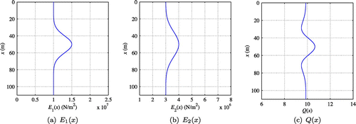
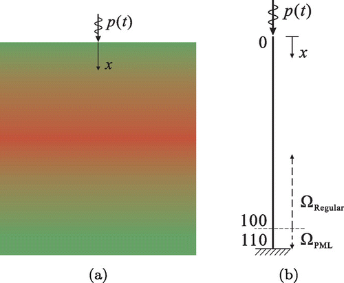
To provide numerical examples, a heterogeneous semi-infinite solid medium with smoothly-varying material properties was defined. The medium was modeled as a one-dimensional PML-truncated domain, with the regular domain occupying , and the PML placed at
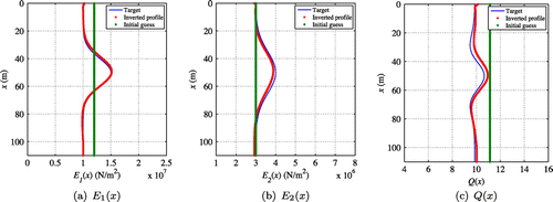
, as shown in Figure . The medium’s viscoelastic properties were described using the Generalized Maxwell Body. Figure (a) and (b) depict the target
and
profiles within the PML-truncated domain. Both profiles show bell-shaped variations along the depth direction with peak values of
and
at
, respectively, as represented by the following equations:
(73)
(73)
(74)
(74)
With the and
profiles, the target damping parameter
can be determined by Equation (Equation3
(3)
(3) ). Figure (c) presents the target
distribution in the entire domain. The density
is
, and a reflection coefficient of
was imposed on the PML.
Figure 3. (a) Heterogeneous semi-infinite solid medium with smoothly-varying material properties; (b) Schematic of a one-dimensional PML-truncated domain.
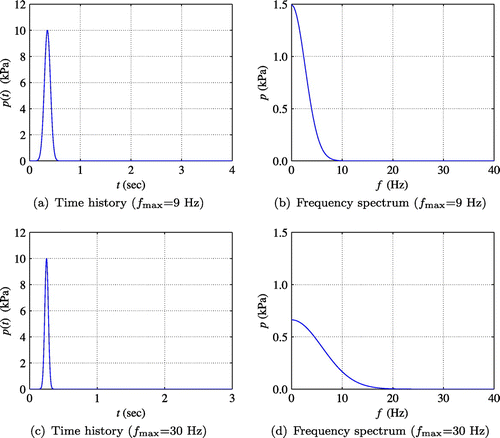
Excitation of the medium was applied on the surface () by two Gaussian pulse-type loads with maximum frequencies of about 9 and 30 Hz, respectively. Figure shows the time history and the frequency spectrum of the excitations. Within this frequency range, it was shown that the two relaxation time parameters
and
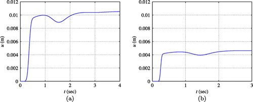
are approximately 0.45 and 0.02, respectively.[Citation10] Figure shows the measured displacement responses
on the surface, which was synthesized by solving the forward problem using the two Gaussian pulse loads. For the solution of all inverse problems in this section, quadratic elements with lengths of
m were used.
Figure (a) and (b) show the reconstructed profiles of and
of the PML-truncated viscoelastic medium using Tikhonov regularization. The inversion process started with initial guesses
and
. Both profiles were updated simultaneously by applying the stress load
with
Hz. Then, using the updated profiles as new initial guesses, subsequent inversion was performed only for
while
was fixed and the higher frequency load (
Hz) was applied. By the described procedure, the smoothly-varying target profiles could be recovered fairly well as shown in Figure (a) and (b). Figure (c) represents the target, initial guess, and inverted
profiles of the medium with the smoothly-varying
and
.
6.2. Layered profiles
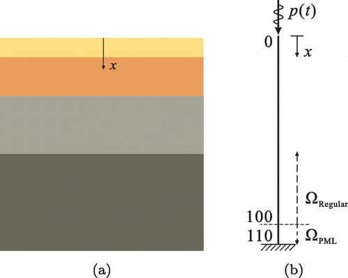
To further demonstrate the developed inversion algorithm, a heterogeneous semi-infinite solid medium with 4 horizontal layers was considered, as depicted in Figure (a). The medium can also be modeled as a one-dimensional PML-truncated domain as shown in Figure (b). The Generalized Maxwell Body was used to describe the medium’s viscoelastic properties.
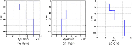
Figure (a) and (b) depict the target and
profiles within the PML-truncated domain, respectively. Both profiles have four distinct layers with the same material interface locations. In this setting,
is different for each of the layers. Figure (c) presents the target
distribution along the entire domain. The density, reflection coefficient of PML, element length, surface loads, and relaxation time parameters are the same as in the case of smoothly-varying material profiles.
Figure 8. (a) Heterogeneous semi-infinite solid medium with 4 horizontal layers; (b) Schematic of a one-dimensional PML-truncated domain.
Three cases were considered for the inversion of layered viscoelastic parameters. First, it was sought to recover the profile, while assuming that the
profile was already known. Secondly, the
profile was sought, while the distribution of
was assumed to be known. Finally, it was sought to reconstruct both profiles simultaneously.
6.2.1. Inverting for 
 when
when 
 is known
This section presents the attempt to reconstruct when
was already known. Equation (Equation71
(71)
(71) ) was used to update
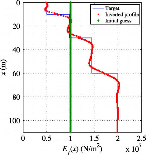
. Figure shows the reconstructed
profile using TV regularization, when
remained the same as the target. The true profile is recovered fairly well. The inversion started with a homogeneous initial guess of
and the regularization factor continuation scheme was utilized to assist in convergence. From this observation, it is noted that the elastic part (
) of the Generalized Maxwell Body can be reconstructed quite well when
is known.
6.2.2. Inverting for 
 when
when 
 is fixed
In this section, the inversion process was implemented for recovering when
was fixed to the target. Equation (Equation71
(71)
(71) ) was used to update
while the
profile was held constant. A homogeneous initial guess of
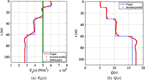
was utilized and the target profile was recovered using TN regularization. Figure (a) shows that the
profile was reconstructed fairly well when
was known. Figure (b) shows the
profile recovered using Equation (Equation3
(3)
(3) ) as well as the reconstructed
profile. From these results, it is apparent that the damping-related modulus (
) of the viscoelastic medium can be recovered quite well provided that the elastic property (
) is known in advance.
6.2.3. Simultaneous inversion for 
 and
and 

Finally, simultaneous recovery of both and
was attempted. This problem entailed reconstruction of both elastic and damping parameters of the Generalized Maxwell Body, given the same surficial measurements used in the case of the single variable inversion. To this end, Equation (Equation71
(71)
(71) ) was used to update
and
profiles at the same time. One difficulty in this problem is that solution multiplicity becomes exacerbated due to the presence of dual inversion variables. To avoid falling to undesirable local minima, initial guesses and regularization factors should be carefully chosen for both inversion parameters, but there is, in general, no guarantee of success.
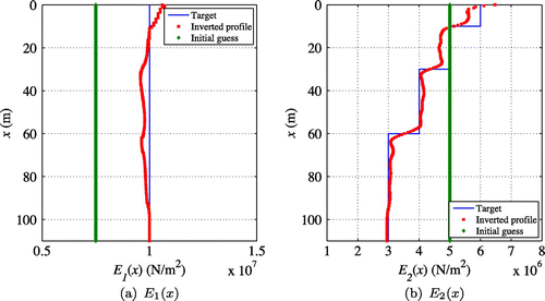
First, two-parameter inversion was considered for a constant target profile and the 4-layer target profile for
depicted in Figure (b). Figure shows the target, initial guess, and inverted profiles for
and
, respectively. As shown in the figure, the reconstruction of
was reasonably accurate, while the reconstruction of
provided moderately reasonable estimates of the thickness, location, and material property values of each layer. Homogeneous initial guesses of
and
were used and then
and
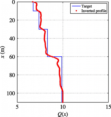
were updated simultaneously at every inversion iteration with the aid of the regularization factor continuation scheme.[Citation24, Citation25] Figure shows the recovered
profile obtained from the inverted
and
results. The agreement between the reconstructed properties and the target properties was marginally successful.
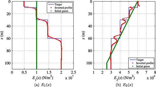
Next, two-parameter inversion was attempted when both profiles were layered. In particular, it was attempted to recover the layered profiles and
depicted in Figure . In this case, simultaneously inverting for both properties at every inversion iteration did not lead to satisfactory reconstruction of the target profiles, regardless of the choice of initial guesses, step lengths, and regularization factors. To attempt to overcome this difficulty, a staggered inversion method was used, where single variable inversion for
was followed by simultaneous inversion with a source frequency continuation scheme.[Citation25] In this example, the details are as follows:
| (1) | Constant and linear initial guesses were used for | ||||
| (2) | Then, the initial guess of | ||||
Figure 16. Reconstructed profiles obtained from Gauss–Newton and Fletcher–Reeves optimization algorithms; is constant and
has 4 layers.
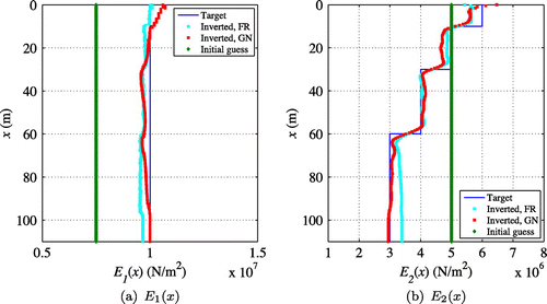
Figure 17. Response misfit versus iteration numbers in the simultaneous inversion; is constant and
has 4 layers.
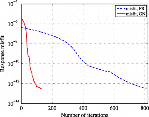
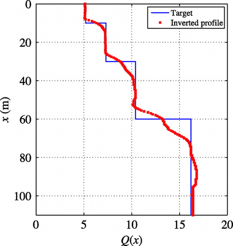
Figure shows the profile constructed from the inverted
and
profiles. Regarding the
profile, there are some errors, but the recovered Q profile characterizes the distribution of the domain’s attenuation reasonably well.
6.2.4. Gauss–Newton versus Fletcher–Reeves optimization method
To investigate the efficiency of the developed Gauss–Newton (GN) approach for full-waveform inversion, results from the GN method were compared with those from the Fletcher–Reeves (FR) conjugate gradient optimization method. Figure compares inverted and
profiles obtained from the GN and FR methods, respectively, when
was held constant and
had 4 layers. Both methods resulted in profiles close to the target. However, it is noted that the accuracy of solutions was improved for the GN profile, especially when
was greater than 50 m. Additionally, it took considerably fewer iterations in the case of GN than in the case of FR. Figure exhibits response misfit versus iteration numbers in the simultaneous inversion. The GN method required 130 iterations, whereas it took 820 iterations when the FR method was used for the inversion.
Figure 18. Reconstructed profiles obtained from Gauss–Newton and Fletcher–Reeves optimization algorithms; both and
have 4 layers.
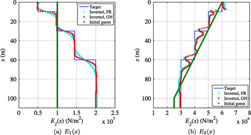
Figure 19. Response misfit versus iteration numbers in the simultaneous inversion; both and
have 4 layers.
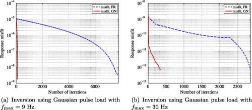
In Figure , GN and FR profiles are compared when both and
have 4 layers. The accuracy of solutions was improved by the developed GN approach compared to the FR, with the GN profile sharper than the FR profile at interfaces. The developed approach also attained substantial improvement on the convergence rate of solutions for both load frequencies
, as seen in Figure . Using
Hz, the GN and FR methods required 110 and 7780 iterations, respectively, to approximate the target. These iteration numbers were 350 and 2860 for GN and FR methods, respectively, when
Hz.
For the case of the constant profile, the CPU times to perform GN and FR inversions were about 430 and 3100 s, respectively. For the case where both
and
were layered, the CPU times for GN and FR inversions were about 770 and 5300 s, respectively. In both cases, the CPU time of GN inversion was less than 15% that of FR inversion.
7. Conclusions
This study presents the development of a Gauss–Newton full-waveform inversion in the time-domain for the reconstruction of elastic and attenuating properties of semi-infinite solid media truncated by PML, using solely the surficial response of the domain to dynamic excitation. The nonlinear optimization problem was resolved using an iterative procedure in the reduced space of the control variables, which were viscoelastic parameters of the PML-truncated domains. The search direction of and
were determined by a Gauss–Newton–Krylov method on a reduced KKT system obtained by second-order Fréchet derivatives of the Lagrangian functional.
The numerical results indicate that, while the elastic properties are well captured, reconstruction of the attenuation profiles is more challenging. Still, satisfactory results were obtained when a staggered scheme was employed. Approximate solutions of the Gauss–Newton inversion exhibited faster convergence behavior and better robustness, while requiring fewer iterations and less CPU time to reconstruct the profiles compared to the Fletcher-Reeves optimization method.
Additional information
Funding
Notes
No potential conflict of interest was reported by the authors.
References
- Becache E, Ezziani A, Joly P. A mixed finite element approach for viscoelastic wave propagation. Comput. Geosci. 2004;8:255–299.
- Becache E, Joly P, Tsogka C. A new family of mixed finite elements for the linear elastodynamic problem. SIAM J. Numer. Anal. 2002;39:2109–2132.
- Ma S, Liu P. Modeling of the perfectly matched layer absorbing boundaries and intrinsic attenuation in explicit finite-element methods. Bull. Seismol. Soc. Am. 2006;96:1779–1794.
- Day SM. Efficient simulation of constant Q using coarse-grained memory variables. Bull. Seismol. Soc. Am. 1998;88:1051–1062.
- Ely GP, Day SM, Minster JB. A support-operator method for viscoelastic wave modelling in 3-D heterogeneous media. Geophys. J. Int. 2008;172:331–344.
- Martin R, Komatitsch D. An unsplit convolutional perfectly matched layer technique improved at grazing incidence for the viscoelastic wave equation. Geophys. J. Int. 2009;179:333–344.
- Dhemaied A, Rejiba F, Camerlynck C, Bodet L, Guerin R. Seismic-wave propagation modeling in viscoelastic media using the auxiliary differential equation method. Bull. Seismol. Soc. Am. 2011;101:413–420.
- Carcione JM. Wave propagation in anisotropic linear viscoelastic media: theory and simulated wavefields. Geophys. J. Int. 1990;101:739–750.
- Yan HY, Liu Y. High-order finite-difference numerical modeling of wave propagation in viscoelastic tti media using rotated staggered grid. Chin. J. Geophys. 2012;55:252–265.
- Assimaki D, Kallivokas LF, Kang JW, Li W, Kucukcoban S. Time-domain forward and inverse modeling of lossy soils with frequency-independent Q for near-surface applications. Soil Dyn. Earthquake Eng. 2012;43:139–159.
- Kang JW, Kallivokas LF. Mixed unsplit-field perfectly matched layers for transient simulations of scalar waves in heterogeneous domains. Comput. Geosci. 2009;14:623–648.
- Brezzi F, Fortin M. Mixed and hybrid finite element methods. New York (NY): Springer; 1991.
- Tikhonov A. Solution of incorrectly formulated problems and the regularization method. Sov. Math. Dokl. 1963;4:1035–1038.
- Rudin L, Osher S, Fatemi E. Nonlinear total variation based noise removal algorithms. Physica D. 1993;60:259–268.
- Akcelik V. 2002. Multiscale Newton--Krylov methods for inverse acoustic wave propagation [Ph.d. dissertation].
- Saad Y. Iterative methods for sparse linear systems. 2nd ed. Philadelphia (PA): SIAM; 2003.
- Akcelik V, Biros G, Ghattas O. Parallel multiscale Gauss--Newton--Krylov methods for inverse wave propagation. Proceedings of the 2002 ACM/IEEE Conference on Supercomputing; 2002; Baltimore (MD): ACM Digital Library; p. 1–15.
- Askan A, Akcelik V, Bielak J, Ghattas O. Full waveform inversion for seismic velocity and anelastic losses in heterogeneous structures. Bull. Seismol. Soc. Am. 2007;97:1990–2008.
- Epanomeritakis I, Akcelik V, Ghattas O, Bielak J. A Newton-CG method for large-scale three-dimensional elastic full-waveform seismic inversion. Inverse Prob. 2008;24:034015.
- Erlangga YA, Herrmann FJ. Seismic waveform inversion with Gauss–Newton–Krylov method. SEG Technical Program Expanded Abstracts. SEG Annual Meeting; 2009 October; Houston, TX. Vol. 28; p. 2357–2361.
- Pakravan A, Kang JW. A Gauss–Newton full-waveform inversion for material profile reconstruction in 1D PML-truncated solid media. KSCE J. Civ. Eng. 2014;18:1792–1804.
- Eisenstat SC, Walker HF. Choosing the forcing terms in an inexact Newton method. SIAM J. Sci. Comput. 1996;17:16–32.
- Nocedal J, Wright S. Numerical optimization. New York (NY): Springer; 1999.
- Kang JW, Kallivokas LF. The inverse medium problem in 1D PML-truncated heterogeneous semi-infinite domains. Inverse Prob. Sci. Eng. 2010;18:759–786.
- Kang JW, Kallivokas LF. The inverse medium problem in heterogeneous PML-truncated domains using scalar probing waves. Comput. Methods Appl. Mech. Eng. 2011;200:265–283.
Appendix 1
Second-order Fréchet derivatives of the Lagrangian functional
The second-order Fréchet derivatives of in the KKT system (Equation (Equation39
(39)
(39) )) can be obtained by taking the second variation of the Lagrangian with respect to the state, adjoint, and control variables. For example,
can be obtained by the following variational calculus; given arbitrary functions
and
with
,
, the perturbation of the Lagrangian (Equation14
(14)
(14) ) can be written as:
(A1)
(A1)
Differentiating Equation (EquationA1(A1)
(A1) ) with respect to
and
, respectively, and then evaluating the resulting equation at
yields:
(A2)
(A2)
Therefore,(A3)
(A3)
The rest of the Fréchet derivatives in Equation (Equation39(39)
(39) ) can be derived similarly. There result the following expressions:
Table A1. Second-order Fréchet derivatives of .
Table A2. (Continued)

