 ?Mathematical formulae have been encoded as MathML and are displayed in this HTML version using MathJax in order to improve their display. Uncheck the box to turn MathJax off. This feature requires Javascript. Click on a formula to zoom.
Abstract
In this work, a parameter based on correlation of signals using mathematical morphology and other two parameters based on energy of a vibration signal using wavelet transform and bispectrum theory are used for approximate location of damage in a steel clamped-free beam. The experimental data are obtained through accelerometers placed along the sample. The system is excited using impact hammer. A preliminary location of the damage is found using the position of the accelerometer that has a higher energy change when it is compared to the signal of the system with and without damage. The mathematical models are obtained using 2D elasticity theory and the finite element method. The numerical and experimental data are approximated using the particle swarm optimization method, and this way, it is possible to adjust the location and severity of the damage. The procedure is also applied to a free–free steel beam with two damages and a sandwich beam.
1. Introduction
An area of great interest in the field of engineering is the study and identification of structural damage. There are a lot of mechanical tests and techniques used to detect cracks and possible failures in mechanical structures. One of the major problems for the industry lies on acquiring reliable and non-destructible results.
Most identification techniques are based on modal parameters measured using only a few modes of vibration and/or modal frequencies of the structure that can easily be obtained by dynamic testing. The results are obtained with dynamic measurements at different times, corresponding to two moments of the structure lifetime (usually with the model in good condition and damaged).
The main methods based on vibration signals are as follows: mode shape curvature method,[Citation1,2] change in flexibility method,[Citation1,2] change in flexibility curvature method,[Citation1,2] strain energy method,[Citation1,3] statistical methods,[Citation4–11] wavelet analysis [Citation12–16] and response surface methodology.[Citation17] Defects in components of machinery and structures can be detected by monitoring vibration.[Citation6]
The bispectrum, a third-order statistic and kurtosis, a fourth-order moment, help to identify faults in mechanical components. The bispectrum technique relates one set of mixing waves through the spectral coupling.[Citation4–10]
Mathematical morphology (MM) is a nonlinear analysis method, which has been developed and widely applied to various fields of image processing and analysis. When MM is used in signal processing, the information of local morphological features of the signal is the only determinative factor. By morphological signal decomposition, a complex signal can be separated from the background and decomposed into various components reserving morphological features of the signal. Literature review reveals that the research of morphology analysis in one-dimensional (1-D) signals, especially in machine fault diagnosis, is still limited.[Citation18,19]
Identification, localization and quantification of structural damage can be performed through a model updating procedure. Model updating methods require a baseline finite element model of the undamaged structure, which imposes a restriction on their applicability and can become very problematic especially for large and complex structures.[Citation20]
The correlation techniques are a mixture of visual and numerical means to identify the differences between measurements and predictions. Whereas numerical correlation techniques return a numerical value, visual means of correlation are subjective and of qualitative nature.[Citation21] Some of the basic correlation tools include simple tabulation or plotting the measured and predicted eigenvalues. A more strict correlation is the use of the so-called modal assurance criteria (MAC).[Citation20–22]
When materials in a structure suffer damage, the mechanical response of the structure is modified, particularly in the vicinity of the damaged zones. Such local perturbations in the structural response are generally very small, but they can be detected using wavelet transform techniques.[Citation16]
Recently, wavelet analysis has shown its inherent merits in damage detection over traditional methods due to its ability to closely examine the signal with multiple scales to provide various levels of detail and approximations. The use of wavelet transform to identify damage from mode shape has been one of the most popular techniques. These methods treat mode shape data as a signal in spatial domain, and they use spatial wavelet transform technique to detect the signal irregularity caused by damage. A damage detection index called wavelet packet energy rate index (WPERI) was proposed by [Citation15] for the damage detection of beam structures. The measured dynamic signals are decomposed into the wavelet packet components, and the wavelet energy rate index is computed to indicate the structural damage.
The aim of this work was to analyse structural changes through the inclusion of damage (crack) with known formats and positions in the samples. The damage in steel clamped-free beam is analysed considering samples with and without structural modifications. The damage location is investigated by varying the damage position in the mathematical model and comparing the numerical and experimental data. The mathematical models are obtained using the finite element method (FEM). The experimental data are obtained using the impact hammer and an accelerometer placed in different positions along the sample. The statistics procedures are used in qualitative analysis. In order to approximate the experimental and numeric frequency response functions (FRF) data, the particle swarm optimization (PSO) [Citation23–25] method is used. The first approximations of the damage position are obtained using three different parameters based on the energy of the signal and using morphological analysis, bispectrum and wavelet analysis. Using this procedure and making a sweep of the modified finite element position along the sample, it is possible to identify, with great precision, the location and severity of the damage through the comparison of the experimental and numeric modal parameters. The procedure is also applied to a free–free steel beam with two damages and a sandwich beam.
2. Mathematical models
2.1. Two-dimensional elastic model
The two-dimensional (2-D) elastic analysis of the sandwich beam was performed by assuming that the materials are homogeneous and present a linear behaviour and that the materials are perfectly bonded in the interfaces. The continuity of the displacements at the interfaces of the materials that make up the sandwich beam (continuous and fully glued interfaces) allows the finite elements to assemble in the conventional way, even with different materials.
In this work, cubic Lagrangian Finite Element (16 nodes) is used for the analyses and the elastic components of the displacement u = (u, v) can be interpolated as follows:(1)
(1)
where are the pairs
that represent the displacement components at node i of the element and ϕi(x) represents the Lagrangian interpolation functions (well known in the classical books of finite elements).
The linear strains vector is related to the generalised displacement vector in the following manner:(2)
(2)
where [B] is a (3 × 32) matrix relating the three strains to the generalised displacements and is given by:(3)
(3)
The element stiffness matrix, [K] is obtained by integration and its expression is found in the conventional finite element classical books:(4)
(4)
where t denotes the thickness of the element, A denotes the area of the element and [D] is the (3 × 3) matrix, which relates three stresses and three strains,(5)
(5)
The [D] matrix is written as a function of the elastic material parameters, and the adjustment of these parameters as a function of frequency was the main objective of this work. The mass matrix is obtained using the following integral:(6)
(6)
where ρ is the material density and [Φ] is a matrix of the order (2×32) of Equation (Equation1(1)
(1) ).
For punctual external forces as f(x, t) = f0 sin (ωt) acting on node i and the balance of the element in relation to the harmonic analysis can be written as:(7)
(7)
where(8)
(8)
and(9)
(9)
and the position is not equal to zero at 2i when the force is applied in the y direction and 2(i − 1) when the force is applied in the x direction.
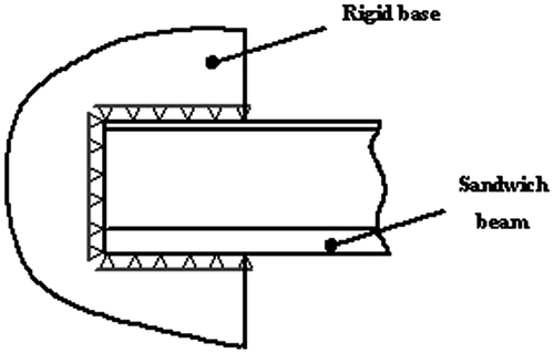
Figure shows the detail of how the boundary condition of type clamped end was imposed on the sandwich beam. As can be seen, this condition is much better represented with 2-D elements, because null displacements are imposed only on the nodes in contact with the rigid base (unlike the beam element).
Figure shows the pattern construction of the homogeneous finite element mesh (it shows only a 3 mm thickness band along the height of the beam). Note that elements with a length of 3 mm were used to keep the aspect ratio limited to 5 for the elements of the steel sheet. This formulation is also used to simulate the dynamical behaviour of a steel clamped beam. In this case, the model is simplified.
2.2. Bispectrum theory
The statistical properties of a stationary random process are completely described by its mean value μ (first order moment) and variance σ2 (second-order central moment) if and only if its probability density function has a Gaussian distribution. Higher order statistics (HOS) measures, such as higher order moments, are extensions of second-order measures to higher orders and cannot provide additional information about a signal if it is Gaussian. However, many signals found in the industrial field are non-Gaussian, e.g. vibrational signals of rotating machines. Therefore, HOS may be used to extract information about signals and systems which cannot be obtained from conventional statistics. The most used traditional signal processing measure is the power spectrum, that is the decomposition over frequency of the signal power and is therefore related to the signal variance σ2. The bispectrum (third-order spectrum) can be viewed as a decomposition of the third moment (skewness) of a signal over frequency and as such can detect non-symmetric nonlinearities. For a stationary random process, the discrete bispectrum B(k, l) can be defined in terms of the signal’s discrete Fourier transform X(k) as:
(10)
(10)
where denotes the expectation operator. It should be noted that the bispectrum is complex-valued (it contains phase information) and that it is a function of two independent frequencies, k and l. Furthermore, it is not necessary to compute B(k, l) for all (k, l) pairs, due to several symmetries existing in the (k, l) plane. If ωk, ωl and ωk + l are independent, each one will have an independent random phase (relative to each other). Therefore, the bispectrum is a statistical is of great importance in the study of those nonlinear vibrations where the relationships between three spectral components are in question, such as generation of combinational resonance modes or quadratic mode couplings [Citation4].
2.3. Wavelet theory
The continuous wavelet transform is defined as follows [Citation15]:(11)
(11)
where(12)
(12)
is a window function called the mother wavelet, where a is a scale and b is a translation. The term wavelet means a small wave. The smallness refers to the condition in which this (window) function is in the finite length (compactly supported). The wave refers to the oscillatory condition of this function. The term mother implies that the functions with different support regions that are used in the transformation process are derived from one main function, or the mother wavelet. In other words, the mother wavelet is a prototype for generating the other window functions.
Wavelet packets consist of a set of linearly combined usual wavelet functions. The wavelet packets inherit the properties such as orthonormality and time–frequency localization from their corresponding wavelet functions. A wavelet packet is a function with three indices where integers i, j and k are the modulation, scale and translation parameters, respectively,
(13)
(13)
The wavelet packet component signal can be represented by a linear combination of wavelet packet functions
as follows:
where the wavelet packet coefficients can be obtained from
(15)
(15)
and(16)
(16)
The wavelet packet energy index is used to identify the initial locations of damage. In this case, the signal energy at j level is first defined as:
(17)
(17)
After manipulations, it is possible to find the wavelet packet component as the stored energy in the component signal
as:
(18)
(18)
The WPERI is used to indicate the localization of the structural damage. The rate of signal wavelet packet energy at j level is defined as
(19)
(19)
where is the component signal energy
at j level without damage, and
is the component signal energy
with some damage.
2.4. Mathematical morphology
The vibration signal dealt with in this study is a discrete 1-D signal, and the multivalued morphological transformation for this type of signal is addressed in following paragraphs.[Citation18,19]
If f(n) is the original 1-D signal, which is the discrete function over a domain F = (0; 1; 2; … ; N − 1) and g(n) is the SE (flat structuring element), which is the discrete function over a domain G = (0; 1; 2; …; M − 1), two basic morphological operators, the erosion and the dilation, can be defined as:(20)
(20)
(21)
(21)
where denotes the erosion operator and ⊕ denotes the dilation operator.
Based on the dilation and erosion, two other basic morphological operators, the opening and the closing, can be further defined as:(22)
(22)
(23)
(23)
where stands for the opening operator and
for the closing operator.
These four morphological operators can all be used to extract morphological features of a signal, but different operators fit different morphological features.
Multi-scale MM refers to a morphology analysis with SEs at different scales. The SE scale, especially the length scale, is important for the multi-scale morphology analysis of 1-D signals. The multi-scale morphological operations have also opening and closing operations. Table shows the double-dot structuring element used in the analysis. The correlation coefficient of two pattern spectra is expressed as(24)
(24)
Table 1. Multi-scale structuring elements.
where P1 and P2 represent two different pattern spectra, and ρ is their correlation coefficient which measures the similarity of two signals (with and without damage).
2.5. PSO method
In this work, the physical parameters of a steel clamped-free beam are estimated using measured and numeric FRFs. The mathematical models are obtained using the FEM. In order to approximate the experimental and numeric FRF data, the PSO method is used. The PSO algorithm is a biologically inspired algorithm motivated by a social analogy. Sometimes, it is related to the evolutionary computation techniques, basically with the genetic algorithms and evolutionary strategies, but there are significant differences among those techniques.[Citation23–25]
The PSO algorithm is population based: a set of potential solutions evolves to approach a convenient solution (or set of solutions) for a problem. Being an optimization method, the aim is finding the global optimum of a real-valued function (fitness function) defined in a given space (search space).
In the PSO algorithm, each individual is called a ‘particle’ and is subject to a movement in a multidimensional space that represents the belief space. Particles have memory, thus retaining part of their previous state. There is no restriction for particles to share the same point in belief space, but in any case, their individuality is preserved. Each particle’s movement is the composition of an initial random velocity and two randomly weighted influences: individuality, the tendency to return to the particle’s best previous position, and sociality, the tendency to move towards the neighbourhood’s best previous position.
The ‘continuous’ version uses a real-valued multidimensional space as belief space and evolves the position of each particle in that space using the following equations:(25)
(25)
(26)
(26)
where i is the particle index; k is the discrete time index; v is the velocity on ith particle; x is the position of the ith particle; p is the best position found by ith particle (personal best); G is the best position found by swarm (global best, best of personal bests); γ1,2 are random numbers on the interval [0,1] applied to ith particle
The common PSO algorithm is as follows:(27)
(27)
where ϕ is the inertia function, and α1 and α2 are the acceleration constants.
2.6. Modal parameters
Methods that consider the modal changes are also used in the identification of damage (structural changes). A method of setting modal (MAC) is used to compare pairs of modes. The matrix coefficients are obtained by [Citation26]:(28)
(28)
where and
denote the numeric and experimental modes; the superscript symbol T denotes the transpose of a vector and the subscript superscript symbol * denotes the complex conjugate vector.
A MAC value close to 1 suggests that the two modes are well correlated. An overall mode shape indicator may be calculated from:(29)
(29)
where n is the number of modes.
3. Results
Figure shows the flowchart of the damage identification method with four steps.
3.1. Experiment
The geometric dimensions of the experimental clamped-free beam steel sample are as follows: length = 0.84 m; thickness = 0.0127 m and width = 0.0254 m. The effective length for the clamped free is 0.825 m.
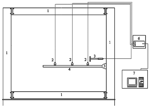
The experimental data are obtained using the impact hammer, and one accelerometer displaced along the sample in the positions 0.125, 0.225, 0.325, 0.425, 0.525, 0.625, 0.725 and 0.825 m. The excitation force was applied in the same position (between first and second accelerometers) for all tests. Figure shows schematically the basic components of the vibration testing system. The system consists of a rigid structure (1), accelerometers PCB 333B (2), impact hammer PCB 086C03 (3), beam sample (4), rigid termination (5), signal analyzer HP 3567 and a microcomputer (7).
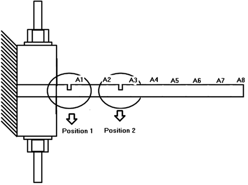
The structural modifications (Figure ) were introduced in positions near 0.075 m (position 1) and 0.245 m (position 2). For these two cases, the data were collected for the system with and without damage with three levels of damage (damage 1, damage 2 and damage 3) whose geometrical parameters for both cases are as follows: length of 0.001 m and heights of 0.001, 0.0025 and 0.0045 m. A1–A8 represents the positions of the accelerometers.
The first step was to obtain data in the frequency domain and time domain. The data in the frequency domain are used to obtain the modal parameters, and the data in the time domain are used for the statistical methods application. The inverse of FRF was used aiming for the signals to have the same excitation force amplitude.
3.2. Visualisation
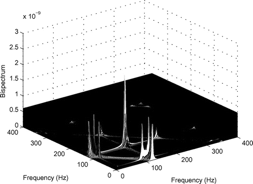
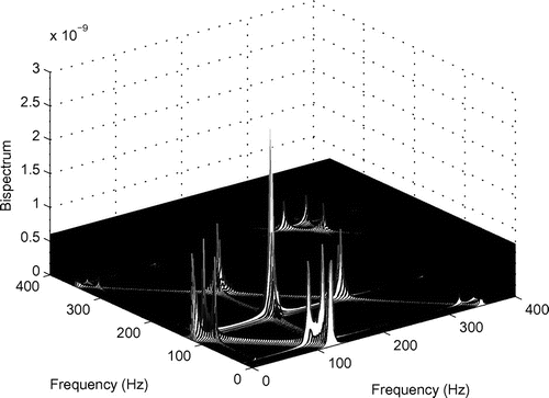
In an attempt to identify the damage, we applied the bispectrum technique in the signal in time domain. Figures and show the bispectrum of the signal of the accelerometer placed at position 0.425 m for the system with and without damage. The curves present differences, but it is visually difficult to establish a reliable parameter for analysis.
3.3. Damage position
It was defined a relative parameter that contained the sum of all values of the bispectrum (spectral energy) defined by (Equation30(30)
(30) ) and (Equation31
(31)
(31) ):
(30)
(30)
(31)
(31)
where IndBb is the bispectrum parameter of the system with damage; IndBa is the bispectrum parameter of the system without damage; n is the number of points in the frequency range (in this case n = 400); k and l are the frequency points varying from 1 to 400 (increment frequency of 1 Hz).
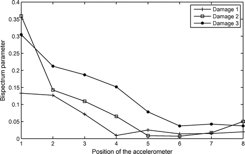
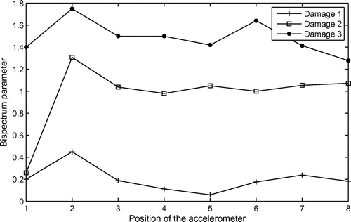
Figures and show the values of the parameter Brel for all positions of the accelerometer. Figure shows the curves for the system with damage in position 1 and Figure for the system with damage in position 2. It can be noticed that the great values for all cases of damage are found for the position 1 of the accelerometer (Figure ) and position 2 of the accelerometer (Figure ). In all situations, the great values correspond to the real near position of the damages.
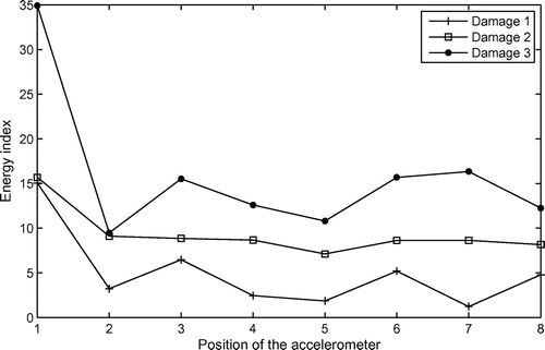
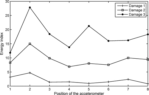
Similar results were found using the energy index based on the wavelet transform signal. Figures and show the energy parameter values obtained by (19).
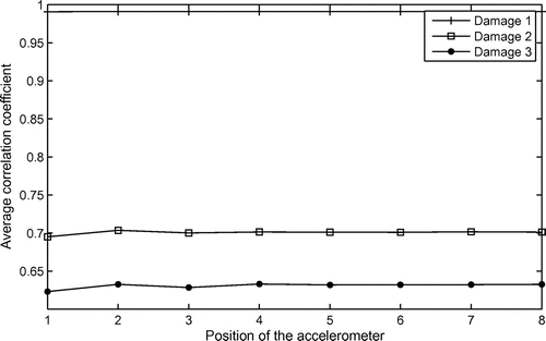
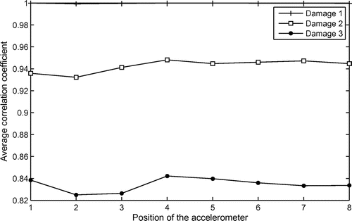
Finally, a correlation coefficient of signals was used taking into account the pattern spectrum of two signals, with and without damage. The results obtained with this coefficient were more stable (lower fluctuations) and, in this case, the lower values were near the damage position (Figures and ).
3.4. Damage parameters
After verifying the approximated position of the damage, a mathematical beam model was obtained through the FEM. For all analyses were written subroutines in Fortran and Matlab languages. The influence of the severity degree of damage was also evaluated. The MAC number (28) and the error parameter (29) were used to validate the numeric and experimental data. Tables and show the values of these parameters for the beam system with three different damage levels. The maximum error is of the order of 0.08% for the sample with damage in position 1 and 0.16% for the sample with damage in position 2.
Table 2. MAC number (damage in position 1).
Table 3. MAC number (damage in position 2).
Finally, we tried to adjust the possible location of the damage based on the natural frequencies variations and a performance index defined by Equation (Equation32(32)
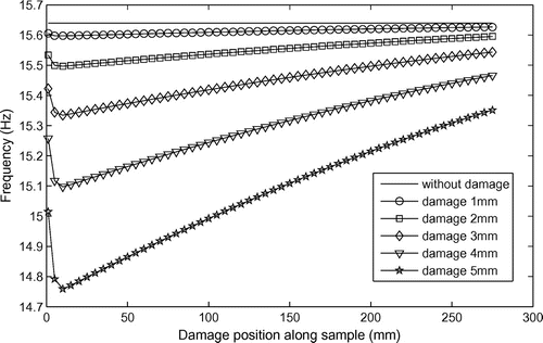
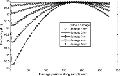
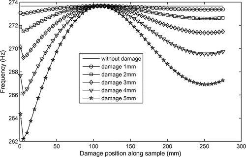
(32) ). To adjust the damage position, it was made a sweep of the damage position along the sample. The position analysed is in agreement with the position of the accelerometers showed in Figures . As the greater levels of energy are near the first accelerometer (damage in position 1) and second accelerometer (damage in position 2), it was considered in the mathematical model (FEM model) the damage position by varying from 0 to 0.275 m with increment of 1 mm (the length of the damage). The position 0.275 m (position in the middle of the second and third accelerometers) was used for identification of the damage in position 2. To identify the damage in position 1, it was necessary to vary the position of the damage from 0 to 0.175 m. In all cases, it was considered damage with length of 1 mm and the height varying from 1 to 5 mm with increment of 1 mm. Figures show the variation of the first, second and third natural frequencies.
The numerical and experimental data are approximated using the PSO method, and this way, it is possible to adjust the localization and the severity of the damage. The first three natural frequencies were considered, and the following parameter error checking was used:
(32)
(32)
where and
represent the variation of the experimental and numeric frequencies. Three input variables were used in the optimization process: position, length and height of the damage.
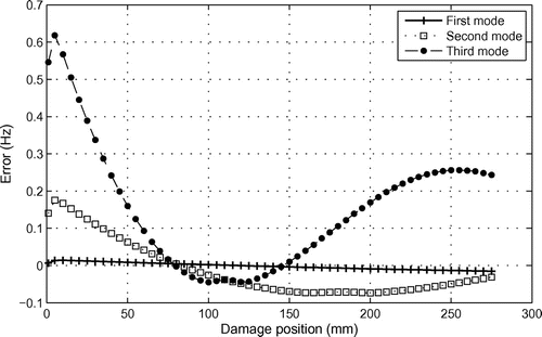
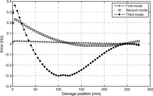
Figures and show the values of the error parameter defined in Equation (Equation32(32)
(32) ) for two different samples with different damage location. It can be noticed in Figure , that the region of minimal values (intersection of curves) for the three natural frequencies is near 75 mm (near position 1 of damage), and in Figure , the region is near 250 mm (near position 2 of damage).
The optimised parameters for the three systems are shown in Tables and , and the real parameters (reference values) present good agreement. The PSO parameters used are as follows: particles number: 25; velocity 2; acceleration constant: 2.1; inertia weights: 0.9 and 0.6 and number of iterations: 400. The convergence demands great computational time because a finite element mesh with quadratic elements of 16 nodes and 1 mm of size was used. The second sample with damage located at 250 mm from the clamped end presented similar results.
Table 4. Optimised damage parameters (damage in position 1).
Table 5. Optimised damage parameters (damage in position 2).
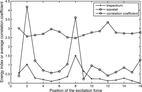
Other analyses were carried out using a steel free–free beam whose dimensions are as follows: length = 0.84 m; thickness = 0.0127 m and width = 0.0254 m. In this case, was used only one accelerometer placed in position 35 cm and the excitation force was applied using an impact hammer in 16 different positions (5–80 cm with step of 5 cm). Two structural modifications were introduced in positions near 0.08 m (length of 0.001 m and height of 0.002 m) and 0.38 m (length of 0.001 m and height of 0.004 m). Figure shows the energy parameter values obtained with bispectrum theory and wavelet transform and the correlation coefficient (the values of this parameter are multiplied by 3.5 to better visualisation). It can be seen two peak values in energy curves and two regions of minimum values in the range correlation curve, near to the positions 2 and 8 of the excitation force. These positions are close to the damage positions. To verify the correct positions and geometric data of the damages, it was used the error parameter defined by (32) and the PSO. As Figure shows two different peaks of energy the geometric constraints imposed for the solution of the optimization problems were as follows: number of damage = 2; positions of the damages: 5 < x1 <15 cm and 25 < x2 <35 cm; length of the damages: 0 < length < 2 mm and height of the damages: 0 < height < 10 mm. The adjusted parameters values were as follows: position of damage 1 x1 = 8 mm, length of 0.975 mm and the height of 2.05 mm; position of damage 2 x2 = 0.278 m, length of 1.005 mm and the height of 3.95 mm. The values are close to the reference values.
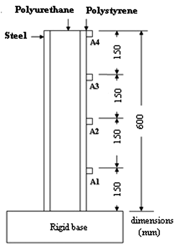
In order to test the efficiency of the method in a more complex system, the parameters of a sandwich beam with damage were adjusted. The sandwich beam experimental sample made with hot-rolled steel associated with polyurethane rigid foam and high impact polystyrene is shown in Figure . The steel thickness is 0.6 mm; the polyurethane is 38.25 mm and the Polystyrene is 1.25 mm and the beam width is 39.18 mm. The experimental data are obtained using the impact hammer and four accelerometers displaced along the sample (A1–A4). The damage was introduced into the system by removing 2 mm from the polystyrene face at the position of 75 mm from the rigid base.
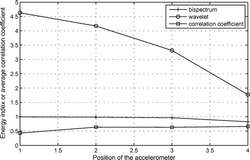
Figure shows the energy parameter values obtained with bispectrum theory and wavelet transform and the correlation coefficient. It can be noticed that the great energy values and the lower values of the correlation coefficient are in the first accelerometer (the accelerometer nearest the damage). Using the error parameter defined in Equation (Equation32(32)
(32) ) and the PSO whose constraints were the damage parameters for the finite elements of the meshes (Figure ) of the polyurethane rigid foam or high impact polystyrene and the position of the damage. The geometric constraints imposed for the solution of the optimization problems were as follows: number of damage =1, positions of the damages: 0 < x < 0.225 m, length of the damages: 0 < length < 4 mm and height of the damages: 0 < height < 2 mm. The adjusted parameters values were as follows: position = 75.5 mm (from the rigid base), length of 1.975 mm (polystyrene face) and the height of 1.25 mm. The values are close to the reference values.
4. Conclusion
It was noticed that the application of statistical methods for assessing damage to structures can be a potential tool. The specific application for cantilever beams presents difficulties due to variations in the vibration modes of the system. Large variations in values for the energy index using bispectrum and wavelet transform were observed, but, in all cases, the two parameters presented a good estimate of the damage position. The results obtained using wavelet transform became evident. This is because this technique differs from conventional power spectrum using parameters that vary increment of frequency in the analysis. Furthermore, the bispectrum is highly recommended for nonlinear systems.
Another parameter, correlation coefficient, using MM and taking into account the correlation of two signals, was used. The results presented minor fluctuations converging to the expected, i.e. lower values for the accelerometer near the damage. Morphological analysis appears to be a potential tool for analysing damage to structures. One of the difficulties lies in the choice of the structuring element.
The correct damage position in a clamped-free steel beam was obtained considering a performance index minimization procedure based on the correlation of numerical and experimental variations of the natural frequencies. To adjust the position of the damage, a sweep of the damage position was made along the sample using the PSO method. The numeric damage position and the optimal geometric damage parameters are close to the real values.
The results are also obtained for a free–free steel beam with two different damages. The damages parameters and positions were adjusted using only the energy parameters to find approximate location of damages and the PSO method to approximate the natural frequencies obtained experimentally and numerically.
The same procedure was applied to sandwich beam.
Disclosure statement
No potential conflict of interest was reported by the authors.
References
- Alvandi A, Cremona C. Assessment of vibration-based damage identification techniques. J. Sound Vib. 2006;292:179–202.10.1016/j.jsv.2005.07.036
- Fan W, Qiao P. Vibration-based damage identification methods: a review and comparative study. Struct. Health Monit. 2011;10:83–111.10.1177/1475921710365419
- Kumar M, Shenoi RA, Cox SJ. Experimental validation of modal strain energies based damage identification method for a composite sandwich beam. Compos. Sci. Technol. 2009;69:1635–1643.10.1016/j.compscitech.2009.03.019
- Rivola A, White PR. Bispectral analysis of the bilinear oscillator with application to the detection of fatigue cracks. J. Sound Vib. 1998;216:889–910.10.1006/jsvi.1998.1738
- Mattson SG, Pandit SM. Statistical moments of autoregressive model residuals for damage localisation. Mech. Syst. Signal Process. 2006;20:627–645.10.1016/j.ymssp.2004.08.005
- McCormick AC. Cyclostationary and higher-order statistical signals processing algorithms for machine condition monitoring [Doctor thesis]. Glasgow (UK): University of Strathclyde; 1998.
- Fugate ML, Sohn H, Farrar CR. Vibration-based damage detection using statistical process control. Mech. Syst. Signal Process. 2001;15:707–721.10.1006/mssp.2000.1323
- Xia Y, Hao H. Statistical damage identification of structures with frequency changes. J. Sound Vib. 2003;263:853–870.10.1016/S0022-460X(02)01077-5
- Nichols JM, Olson CC. Optimal bispectral detection of weak, quadratic nonlinearities in structural systems. J. Sound Vib. 2010;329:1165–1176.10.1016/j.jsv.2009.10.032
- Courtney CRP, Neild SA, Wilcox PD, Drinkwater BW. Application of the bispectrum for detection of small nonlinearities excited sinusoidally. J. Sound Vib. 2010;329:4279–4293.10.1016/j.jsv.2010.04.031
- Kucukgoncu H, Aydin K. Crack identification in beams using Hilbert transform, kurtosis and mode shape rotation deviation curve. Inverse Prob. Sci. Eng. 2013;21:1392–1416.10.1080/17415977.2013.764872
- Radzieński M, Krawczuk M, Palacz M. Improvement of damage detection methods based on experimental modal parameters. Mech. Syst. Signal Process. 2011;25:2169–2190.10.1016/j.ymssp.2011.01.007
- Huang Y, Meyer D, Nemat-Nasser S. Damage detection with spatially distributed 2D continuous wavelet transform. Mech. Mat. 2009;41:1096–1107.10.1016/j.mechmat.2009.05.006
- Nguyen SD, Ngo KN, Tran QT, Choi S-B. A new method for beam-damage-diagnosis using adaptive fuzzy neural structure and wavelet analysis. Mech. Syst. Signal Process. 2013;39: 181–194.10.1016/j.ymssp.2013.03.023
- Wu N, Wang Q. Experimental studies on damage detection of beam structures with wavelet transform. Int. J. Eng. Sci. 2011;49:253–261.10.1016/j.ijengsci.2010.12.004
- Han J-G, Ren W-X, Sun Z-S. Wavelet packet based damage identification of beam structures. Int. J. Solids Struct. 2005;42:6610–6627.10.1016/j.ijsolstr.2005.04.031
- Mukhopadhyay T, Dey TK, Chowdhury R, Chakrabarti A. Structural damage identification using response surface based multi-objective optimization: a comparative study. Arab. J. Sci. Eng. 2015;40:1027–1044.10.1007/s13369-015-1591-3
- Zhang L, Xu J, Yang J, Yang D, Wang D. Multiscale morphology analysis and its application to fault diagnosis. Mech. Syst. Signal Process. 2008;22:597–610.10.1016/j.ymssp.2007.09.010
- Nikolaou NG, Antoniadis IA. Application of morphological operators as envelope extractors for impulsive-type periodic signals. Mech. Syst. Signal Process. 2003;17:1147–1162.10.1006/mssp.2002.1576
- Perera R, Fang SE, Huerta C. Structural crack detection without updated baseline model by single and multiobjective optimization. Mech. Syst. Signal Process. 2009;23:752–768.10.1016/j.ymssp.2008.06.010
- Grafe H. Model updating of large structural dynamics models using measured response functions [ PhD thesis]. London (UK): Imperial College London/University of London; 1998.
- Perera R, Ruiz A. A multistage FE updating procedure for damage identification in large-scale structures based on multiobjective evolutionary optimization. Mech. Syst. Signal Process. 2008;22:970–991.10.1016/j.ymssp.2007.10.004
- Quaranta G, Monti G, Marano GC. Parameters identification of Van der Pol-Duffing oscillators via particle swarm optimization and differential evolution. Mech. Syst. Signal Process. 2010;24:2076–2095.10.1016/j.ymssp.2010.04.006
- Reed HM, Nichols JM, Earls CJ. A modified differential evolution algorithm for damage identification in submerged shell structures. Mech. Syst. Signal Process. 2013;39:396–408.10.1016/j.ymssp.2013.02.018
- Meruane V, Heylen W. An hybrid real genetic algorithm to detect structural damage using modal properties. Mech. Syst. Signal Process. 2011;25:1559–1573.10.1016/j.ymssp.2010.11.020
- Rad SZ. Methods for updating numerical models in structural dynamics [ PhD thesis]. London (UK): Imperial College of Science, Technology and Medicine. Department of Mechanical Engineering; 1997.

