 ?Mathematical formulae have been encoded as MathML and are displayed in this HTML version using MathJax in order to improve their display. Uncheck the box to turn MathJax off. This feature requires Javascript. Click on a formula to zoom.
Abstract
This paper is concerned with the development of a meshless local approach based on the finite collocation method for solving Cauchy problems of 2-D elliptic PDEs in annulus domains. In the proposed approach, besides the collocation of unknown solution, the governing equation is also enforced in the local domains. Moreover, to improve the accuracy, the method considers auxiliary points in local subdomains and imposes the governing PDE operator at these points, without changing the global system size. Localization property of the method reduces the ill-conditioning of the problem and makes it efficient for Cauchy problem. To show the efficiency of the method, four test problems containing Laplace, Poisson, Helmholtz and modified Helmholtz equations are given. A numerical comparison with traditional local RBF method is given in the first test problem.
1. Introduction
Inverse problems appear in various applications, when a phenomenon cannot be observed directly, but only through indirect measurements. Many engineering problems such as identification of material parameters, identification of unknown boundaries, identification of initial boundary conditions, identification of inaccessible boundary conditions can be considered as inverse problems, see for example [Citation1–Citation3]. Unfortunately, inverse problems are generally ill-posed problems in the Hadamard sense,[Citation4] since the existence or uniqueness or the continuous dependence on the data of their solutions may not be ensured. The third criteria have the effect that the observation noise can be arbitrarily amplified and so special cares are required to deal with the inverse problems. Cauchy problems are typical inverse problems, since no information about the solution are available on a part of the boundary. Due to the missing boundary conditions, the solution of these problems does not depend continuously on the data and so are known as ill-posed problems. Cauchy problem of elliptic PDEs arises in many branches of science and engineering, for example, nondestructive evaluation,[Citation5–Citation7] electrocardiography [Citation8] and geophysics.[Citation9] In this paper, we consider an annulus domain with
where
is the outer and
is the inner circle as illustrated in Figure . Then, the following elliptic Cauchy problem in two spatial dimensions is considered as:
(1)
(1)
where is an elliptic operator. We assume that the measured Dirichlet and Neumann’s data are given on the boundary
as follows:
(2)
(2)
(3)
(3)
where is the unit outward normal vector on
, and
,
and
are the given functions. Also, it is assumed that no data are available on
. In practical applications, the given Cauchy data usually contain certain noise. Instead of the exact data
and
, we only have
where stands for noise level and
is a uniformly distributed random number. The uniqueness and conditional stability of the solution to problem (Equation1
(1)
(1) )–(Equation3
(3)
(3) ) was given by Bukhgeim et al. [Citation10]. For some papers on numerical solutions of Cauchy problems, see [Citation11–Citation14]. Meshless methods have attracted much attention in recent years, Refs. [Citation15–Citation19] are among them. Meshless methods using globally supported RBFs and collocation approach have had much application due to approximation power of the native space of RBFs and the simplicity and flexibility of these methods. Although these methods are very simple to be implemented and flexible with regards the enforcement of arbitrary boundary conditions, the problem is the ill-conditioning of the final coefficient matrix even if the initial problem is well posed. For some numerical experiments on the condition number of the interpolation matrices for RBFs, see [Citation20]. Meshless local RBF method first proposed in [Citation21] suggests a local strategy which results in well-conditioned and banded coefficient matrices. By this method, to approximate the unknown solution
at an arbitrary point
, we consider a local region
around this point and derive the collocation in this subdomain. Then, the governing PDE is enforced to give local equations and finally all these local equations are assembled to form a sparse global linear system. This approach has been applied to solve a class of Cauchy problem of elliptic PDEs in [Citation22]. The finite collocation (FC) method is another meshless local strategy proposed in [Citation23]. The main differences between the local RBF method proposed in [Citation21] and the FC method are that in FC method besides collocation of an unknown solution, the PDE governing operator and boundary operator are also enforced in the local collocation systems. In this way, instead of reconstructing the value of the governing PDE operator at each node, the sparse global assembly is obtained by reconstructing the collocation of the unknown solution value on each internal node. Moreover, the accuracy of the FC method can be further improved by considering auxiliary points in local subdomains (
) without changing the global matrix size. In this paper, we propose a local meshless strategy based on the FC method to solve the mentioned Cauchy problem in annulus domains. The localization property of our proposed method reduces the ill-conditioning of the problem and makes it efficient for Cauchy problem. The remaining part of this paper is organized as follows: Section 2 briefly describes our proposed numerical method. Four test problems are considered in Section 3. By the first test problem, a comparison to traditional local RBF method is made and the results show that our approach is more accurate. Our conclusions are summarized in the last section.
2. The proposed local meshless approach for Cauchy problem
We consider a set of scattered nodal points in the domain
and its boundaries
represented by
. Now, let us divide this set of nodal points into four groups
,
,
and
where
is the set of nodes located on the outer boundary
,
is the set of nodes located next to the outer boundary
(i.e. the dashed line in Figure ),
is the set of nodes located on the inner boundary
and
represents the remaining nodes. Let us describe the method by considering these set of nodes separately as follows:
(a) Suppose that . To approximate the unknown solution
at an arbitrary point
, we consider a local region
containing
neighbouring points of
, called a stencil, where
is called the centre of
. The schematic diagram of domain and stencils configurations is shown in Figure . In this paper, the stencils we have considered are
stencils shown in Figure . To approximate the solution
over
, we consider collocation on the subdomain
instead of the whole domain
. So, at each local system
the variable
is approximated by
(4)
(4)
where is the real constant. In this paper, we use multi quadrics(MQ) RBF which is defined as
and is the number of nodal points fallen within the stencil
of
. The term
is known as the ‘shape parameter’, and describes the relative width of the RBF functions about their centres. Unlike other meshless local RBF formulations for which the solution is driven by collocation of unknown solution in a local region,[Citation21] in the FC method and our proposed method, the solution of the PDE is driven by collocation of unknown solution and PDE governing and boundary operators within the local systems, resulting in a sparse global collocation system. So, the PDE governing operator is also enforced in the local collocation systems. Therefore, a series of local systems are formed as follows:
(5)
(5)
where and
represents the collocation matrix for system
, and is composed as follows.
where the scalar values will correspond to the unknown solution values (solution centres) within the computational domain, which are to be determined by the solution of a global system of equations. In this paper, solution centre is a nodal point for which the collocation of unknown solution value is done. Similarly, PDE centre and boundary centre are nodal points for which the collocation of PDE governing operator and PDE boundary operator are done, respectively. The nodal point around which a local system is formed is called the local system centrepoint. The interpolation coefficients
can be obtained from
(6)
(6)
Using Equation (Equation4(4)
(4) ) at the system centrepoint,
, and applying (Equation6
(6)
(6) ), we obtain
(7)
(7)
where and
is a stencil weight vector. Note that the weight vector may be obtained by solving the linear system
and therefore, it is not need to explicitly compute the matrix inverse Four auxiliary points are also considered at each stencil and the PDE operator is imposed at these points. Note that these auxiliary points are only considered in local systems and they do not change the size of the final global system. It is numerically found that using the auxiliary points increase the accuracy of the numerical results.[Citation23] Therefore, by performing Equation (Equation7
(7)
(7) ) for the centrepoint of each local system
, a series of simultaneous equations are formed for the
unknown values of
at the system centrepoints (the number of these equations are equal to the cardinal of
). For each local system, the weight vectors are assembled in the global system.
Figure 1. Two stencils with four auxiliary points in an annual domain. Black circles represent collocation of the unknown solution value (solution centres). Red stars represent collocation of the PDE governing operator (PDE centres and also these nodes are auxiliary points). Green triangles indicate the system centrepoint; the nodes around which the stencil is formed, and at which the global assembly is performed. Blue squares show boundary points. A centrepoint which located on the red-dashed circle is that for this we consider two stencils.
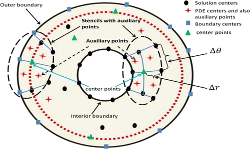
Figure 2. RMS error (left) and condition number (right) versus the shape parameter for the first test problem with no noise.
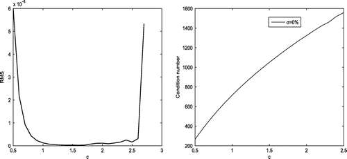
Table 1. Results for numerical approximation of the solution and its normal derivative with different noise levels for the first test problem.
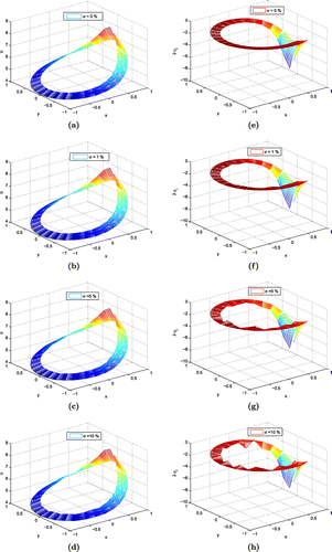
Figure 3. Numerical approximation of the solutions and derivatives with different noise levels over the interior boundary for Poisson equation. (a) Approximate solution with 0% noise, (b) approximate solution with 1% noise, (c) approximate solution with 5% noise, (d) approximate solution with 10% noise, (e) numerical approximation of derivative with 0% noise, (f) numerical approximation of derivative with 1% noise, (g) numerical approximation of derivative with 5% noise and (h) numerical approximation of derivative with 10% noise.
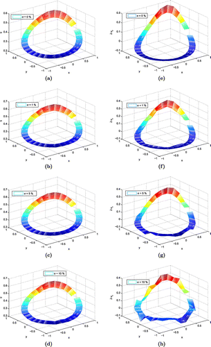
Figure 4. Comparison of the RMS error versus between the proposed method and local RBF method using the first test problem. (a) Approximate solution with 0% noise, (b) approximate solution with 5% noise. FC stands for FC-based method without using auxiliary points, ‘FC+auxil’ stands for FC-based method using auxiliary points and LRBF stands for the local RBF method.
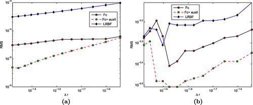
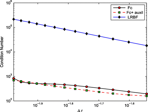
Figure 5. Comparison of the condition number versus using the first test problem. FC stands for FC-based method without using auxiliary points, ‘FC+auxil’ stands for FC-based method using auxiliary points and LRBF stands for the local RBF method.
(b) Suppose that . In this case, we again consider a
stencil and the process is the same as part (a) (i.e. when
) with the difference that the PDE governing operator is imposed at two nodes: at the centre of stencil and the middle point located on the interior boundary.
(c) Suppose that . We again consider a
stencil, but, since we have two kinds of conditions on a part of boundary of this stencil which has intersection with
, two different equations should be obtained, one by imposing the Dirichlet condition, i.e. Equation () and the other by imposing the Neuman condition, i.e. Equation (). So, the matrix
and the vector
are either
or
where the scalar values will correspond to the unknown solution values (solution centres) within the computational domain, which are to be determined by the solution of a global system of equations. To obtain the derivatives of
, the following finite difference scheme which is of order
(
is the difference between two consecutive nodes in polar system)
(d) For the nodes which are located on the outer boundary
, Dirichlet boundary conditions are imposed directly at the final global system.
Table 2. Numerical results with different noise levels on two domains for Laplace equation.
Finally, by assembling the local equations obtained from local systems in parts (a), (b), (c) and (d) above, a sparse global overdetermined system of equations for the unknown values of
is formed. The resulting linear system is sparse, with the number of nonzero entries in each row equal to the number of solution centres in the corresponding collocation system.
Figure 6. Numerical approximation of the solutions and derivatives with different noise levels over the interior boundary for Laplace equation. (a) Approximate solution with 0% noise, (b) approximate solution with 1% noise, (c) approximate solution with 5% noise, (d) approximate solution with 10% noise, (e) numerical approximation of derivative with 0% noise, (f) numerical approximation of derivative with 1% noise, (g) numerical approximation of derivative with 5% noise and (h) numerical approximation of derivative with 10% noise.
3. Numerical demonstrations
Four test problems are considered in this section to study the accuracy of the proposed method. Accuracies of the numerical results are measured by infinity norm error () or root mean square (RMS) error of the approximate solution defined by:
and
where is the numerical solution,
is the exact solution and
is the number of nodes. We consider the equation:
(8)
(8)
where is the outer boundary. For
and
, the equation is Laplace equation; for
and
, we have Poisson equation. For
, we have Helmholtz equation, while for
it becomes modified Helmholtz equation. The domain we considered is a cross section of a pipe for which the outer boundary should be close to the inner boundary, however, to show the effectiveness of the method, five different domains are considered in the following test problems as follows:
The numerical results are obtained with regularly spaced nodal points with respect to the polar system with and
unless otherwise it is stated. Also, in each local stencil we select four auxiliary points that are shown in Figure with red stars. In fact, supposing the centre point in the
th stencil is
, the auxiliary points are chosen as
. In the first test problem, a comparison has been made between our proposed method and the method of local RBF presented in [Citation22].
Table 3. RMS error with different noises and different domains for numerical solutions for Helmholtz equation.
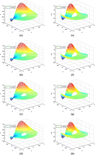
Figure 8. Numerical approximation of solutions and derivatives with different noise levels for Helmholtz equation on domain . (a) Approximate solution with 0% noise, (b) approximate solution with 1% noise, (c) approximate solution with 5% noise, (d) approximate solution with 10% noise, (e) numerical approximation of derivative with
noise, (f) numerical approximation of derivative with 1% noise, (g) numerical approximation of derivative with 5% noise and (h) numerical approximation of derivative with 10% noise.
3.1. Poisson equation
For the first test problem, consider Equation (Equation8(8)
(8) ) with
(Poisson equation) on the domain
. The functions
,
and
are chosen such that the exact solution is:
To see the sensitivity of the numerical solution with respect to the shape parameter in MQ, Figure is presented. This figure represents the RMS error (left) and the condition number of the final matrix (right) versus the shape parameter
. From this figure, it can be seen that the condition number of the global matrix increases by increasing the value of the shape parameter
(because by increasing the value of the parameter
, the shape of the MQ functions becomes more flat). Considering Figure , choosing
moderates the RMS error as well as the condition number of the global matrix. This parameter is fixed at
for the remaining part of this paper. Table presents the accuracy of the numerical approximation of the solution and its normal derivative with different noise levels. Also, the numerical solutions and derivatives with 0, 1, 5 and 10 percent noise level are given in Figure .
Table 4. Results for numerical approximation of the solutions and normal derivatives with different noise levels for modified Helmholtz equation.
Figure 9. Solutions with different noise levels over the interior boundary for modified Helmholtz equation.
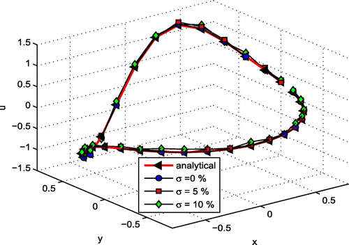
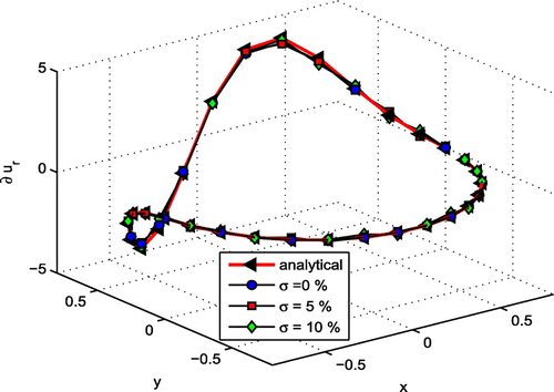
Figure 10. Numerical approximation of derivative with different noise levels over the interior boundary for modified Helmholtz equation.
Here, let us compare the numerical results obtained by the proposed method and the local RBF method of [Citation22]. Figure shows the comparison of the accuracy of the numerical solution between the method of this paper and Local RBF method. Three kinds of results are presented in this figure: results obtained by the FC-based method without using auxiliary points and the results obtained by the FC-based method with using auxiliary points, both proposed in this paper and the result obtained by the local RBF method given in [Citation22]. Also, Figure compares the condition number of the final global matrix. Both Figures and show the effectiveness of our proposed method.
3.2. Laplace equation
Consider the Equation (Equation8(8)
(8) ) with
and
(Laplace equation) on two different domains
and
with the exact solution is given by:
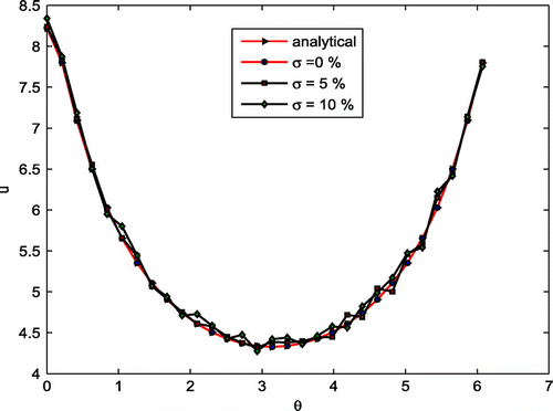
The numerical results obtained with different noise levels are given in Table , while Figure presents the numerical solutions and derivatives with different noise levels for Laplace equation. Moreover, the numerical solutions obtained with different noise levels over the interior boundary for this test problem are presented in Figure .
3.3. Helmholtz equation
Consider the Equation (Equation8(8)
(8) ) with
(Helmholtz equation) and Functions
,
and
are chosen such that the exact solution is:
To see the effectiveness of the method with respect to the domain size, the numerical results obtained on the some different domains ,
,
and
are given in Table by considering
and
. The numerical solutions and derivative with 0, 1, 5 and 10% noise for this test problem are given in Figure on the domain
.
3.4. Modified Helmholtz equation
As the last test problem, consider Equation (Equation8(8)
(8) ) with
(modified Helmholtz equation) on the domains
. Functions
,
and
are chosen such that the exact solution is:
Table presents the numerical approximation of the solution and normal derivative with different noise levels. Figures and present the numerical solutions and derivatives with different noise levels over the interior boundary for modified Helmholtz equation.
4. Conclusions
A meshless local approach based on the finite collocation method was proposed for solving Cauchy problems of 2-D elliptic PDEs in annulus domains. Besides the collocation of unknown solution, the strong form governing equation was also enforced in the local domains. Auxiliary points were also considered to improve the accuracy. The method was compared to the local RBF method of [Citation22] and the results showed the effectiveness of the method. Since the method reduced the original problem into many local small size subproblems, the ill-conditioning of the problem was reduced and the method became efficient for Cauchy problem. Furthermore, the computational cost of the method was the modest due to the usage of strong form equation, collocation approach and that the matrix operations required only the inversion of matrices of small size. The application of the method for solving other kind of inverse problems including large-scale problems is our suggestion for future researches.
Additional information
Funding
Notes
No potential conflict of interest was reported by the authors.
References
- Fu Z, Chen W, Zhang C. Boundary particle method for cauchy inhomogeneous potential problems. Inverse Probl. Sci. Eng. 2012;20:189–207.
- Wei H, Chen W, Sun H, Li X. A coupled method for inverse source problem of spatial fractional anomalous diffusion equations. Inverse Probl. Sci. Eng. 2010;18:945–956.
- Dehghan M, Yousefi SA, Rashedi K. Ritz Galerkin method for solving an inverse heat conduction problem with a nonlinear source term via bernstein multi-scaling functions and cubic b-spline functions. Inverse Probl. Sci. Eng. 2013;21:500–523.
- Hadamard J. Lectures on Cauchy problems in linear partial differential equations. New Haven (CT): Yale University Press; 1923.
- Liu GR, Han X. Computational inverse techniques in nondestructive evaluation. Boca Raton (FL): CRC Press; 2003.
- Marklein R, Mayer K, Hannemann R, et al. Linear and nonlinear inversion algorithms applied in nondestructive evaluation. Inverse Probl. 2002;18:2375–2400.
- Hon YC, Li M. A computational method for inverse free boundary determination problem. Int. J. Numer. Methods Eng. 2008;73:1291–1309.
- Wang YRY. Application of the method of fundamental solution to potential-based inverse electrocardiography. Ann. Biomed. Eng. 2006;34:1272–1288.
- Seieder R, Trampert J. Inverse problems in geophysics. New York (NY): Springer; 1999.
- Bukhgeim AL, Cheng J, Yamamoto M. Uniqueness and stability for an inverse problem of determining a part of boundary. Inverse Probl. 1999;15:1021–1032.
- Delvare F, Cimetière A. A robust data completion method for 2D Laplacian Cauchy problems. In: 6th International Conference on Inverse Problems in Engineering: Theory and Practice. Dourdan; 2008.
- Cheng A, Cheng DT. Heritage and early history of the boundary element method. Eng. Anal. Bound. Elem. 2005;29:268–302.
- Xiong XT. A regularization method for a Cauchy problem of helmholtz equation. J. Comput. Appl. Math. 2010;233:1723–1732.
- Young DL, Tsai CC, Chen CW, Fan CM. The method of fundamental solutions and condition number analysis for inverse problems of Laplace equation. Comput. Math. Appl. 2008;55:1189–1200.
- Abbasbandy S, Sladek V, Shirzadi A, Sladek J. Numerical simulations for coupled pair of diffusion equations by MLPG method. CMES Compt. Model. Eng. Sci. 2011;71:15–37.
- Shirzadi A, Ling L. Convergent overdetermined-RBF-MLPG for solving second order elliptic PDEs. Adv. Appl. Math. Mech. 2013;5:78–89.
- Mirzaei D, Dehghan M. MLPG approximation to the p-Laplace problem. Comput. Mech. 2010;46:805–812.
- Shirzadi A, Ling L, Abbasbandy S. Meshless simulations of the two-dimensional fractional-time convection--diffusion--reaction equations. Eng. Anal. Bound. Elem. 2012;36:1522–1527.
- Kazem S, Rad JA, Parand K, Shaban M, Saberi H. The numerical study on the unsteady flow of gas in a semi-infinite porous medium using an RBF collocation method. Int. J. Comput. Math. 2012;89:2240–2258.
- Boyd JP, Gildersleeve KW. Numerical experiments on the condition number of the interpolation matrices for radial basis functions. Appl. Numer. Math. 2011;61:443–459.
- Lee CK, Liu X, Fan SC. Local multiquadric approximation for solving boundary value problems. Comput. Mech. 2003;30:396–409.
- Chan H-F, Fan C-M. The local radial basis function collocation method for solving two-dimensional inverse cauchy problems. Numer. Heat Transfer Part B: Fundam. 2013;63:284–303.
- Stevens D, Power H, Meng C, Howard D, Cliffe K. An alternative local collocation strategy for high-convergence meshless PDE solutions using radial basis functions. J. Comput. Phys. 2013;254:52–75.

