 ?Mathematical formulae have been encoded as MathML and are displayed in this HTML version using MathJax in order to improve their display. Uncheck the box to turn MathJax off. This feature requires Javascript. Click on a formula to zoom.
Abstract
In this study, a synthesis method for a non-integer periodic function generator of a four-bar mechanism using a Haar wavelet is presented. Using wavelet theory, the mathematical model for the output of a four-bar mechanism is established. Next, the characteristics of the four-bar mechanism output variable are described by the wavelet feature parameters; the relationship of the wavelet feature parameters between the output and its translation or dilation is also investigated. Based on this finding, three numerical atlas databases comprising of 203,500 groups of basic dimensional types of planar four-bar mechanisms, 148,995 groups of basic dimensional types of spherical four-bar mechanism and 11,175 groups of basic dimensional types of planar slider–crank mechanism are compiled. According to the internal relationship between the wavelet feature parameters, the sizes of the objective mechanism can be obtained using fuzzy recognition. Based on a genetic algorithm, optimization of the link parameters can be realized. Three examples are presented to demonstrate the efficacy and practicality of the proposed theory.
1. Introduction
Four-bar mechanisms are essential components in mechanical transmissions; they also play an important role in many others applications, such as industrial automation, electromechanical integration, agricultural modernization and military defence systems. A number of methods for the dimensional synthesis of four-bar mechanisms have been proposed.
Freudenstein [Citation1] developed a formula to obtain the features of a four-bar mechanism to approximately describe an arbitrary function in a limited range using several precision points. This method has been applied to numerous mechanism synthesis problems over the past several decades. Based on the classical Freudenstein’s equation, Bai and Angeles [Citation2] proposed a unified robust algorithm for input–output analysis of a four-bar mechanism. Using this algorithm, Suixian et al. [Citation3] presented an approach to select the precision points for functional synthesis of a spherical four-bar mechanism. For the same problem, a polynomial approximation method using five precision points was proposed by Alizade and Kilit [Citation4], where a constant offset to the output angle is used as an additional design parameter. Further study of function generation of spherical four-bar mechanism was discussed by Alizade and Gezgin [Citation5] using six independent parameters. Kulmani et al. [Citation6] used five precision points to synthesize the output function of a four-bar mechanism. Jacek [Citation7] proposed a numerical method to synthesize the open path of a four-bar mechanism using the sine function. Dimensional synthesis of path and motion generators is particularly worthy of note, as performed by Russell [Citation8–10], who presented a new precision point synthesis of a spatial RRSS and 4R mechanism. Francisco et al. [Citation11] proposed a geometrical adaptation method that reduced the number of optimized parameters and eliminated the effect of position, orientation and size of the curve in an open-path synthesis of a four-bar mechanism. However, the synthesis methods described above have to solve complex non-linear equations; with an increasing number of given locations, solutions become difficult to obtain.
The simulated evolutionary method was then applied to mechanism synthesis to solve this problem. Fang [Citation12] presented an approach to the problem of simultaneous types and dimensional synthesis of a four-bar mechanism using genetic algorithms. Based on the differential evolution and geometric centroid of precision points, Shiakolas [Citation13] presented a method for optimum synthesis of path-generating mechanisms. Peñuñuri et al. [Citation14] proposed a multitask synthesis methodology for planar mechanisms using differential evolution. Matekar and Gunesh [Citation15] improved differential evolution by presenting a modified error function and corresponding objective function for path synthesis of a four-bar mechanism. Mirmahdi and Norouzi [Citation16] considered the distribution of five precision points and both stroke angles of the input and output as optimization variables; they also used different heuristic optimization methods to synthesize the output of a four-bar mechanism. These methods require a complex process of comparison and evolution; the slow convergence may also be disappointing.
The atlas method was then developed to overcome this difficulty. This method was first proposed by Alt, followed by Svoboda [Citation17]; then, Hrones and Nelson [Citation18] presented an atlas that contained almost then thousands curves of four-bar mechanisms. Using this method, the size of the required mechanism could be obtained easily but with low synthesis efficiency. In recent years, the numerical atlas method gradually replaced the classical atlas method in mechanism synthesis problems. Nie et al. and Mullineux [Citation19, 20] solved planar and spatial mechanism synthesis problems using the numerical atlas method. Based on Fourier series theory, Yu and Wang et al. [Citation21, 22], respectively, presented a theoretical method for planar four-bar mechanism path synthesis and rigid-body guidance synthesis. Chu [Citation23] applied this theory to the path synthesis problem of a spherical four-bar mechanism and provided an effective method for spherical four-bar path synthesis. Cong et al. [Citation24] proposed a hybrid computer-aided linkage design system to synthesize open and closed planar curves using Fourier series. Based on the research of the references,[Citation23, 25, 26] a Fourier series is an appropriate method to analyse a closed path or periodic function synthesis when using the numerical atlas method. However, for the non-integer periodic function synthesis problem, due to the limitations of Fourier series, the partial output variable curve must be expanded to include the periodic function, and the synthesis results cannot guarantee that the task curve is approximated accurately.
As a new algorithm, the wavelet transform was first proposed in geology to analyse data from seismic surveys. In recent decades, it has developed rapidly into a mature theory. The primary idea of a wavelet transform is to analyse the signal form in the various frequency bands using dilation and location parameters so that information can be extracted from the task non-integer periodic function effectively. The wavelet transform was applied to describe the non-integer periodic function curve of a planar four-bar mechanism for the first time by Wu et al. [Citation27]. Then, Wang et al. [Citation28] presented a wavelet multi-resolution analysis and fractal theories to synthesize the path generation of a planar four-bar mechanism. Gloria et al. [Citation29] developed a new method based on wavelets and a neural network to describe the path of crank–rocker mechanisms. The aim of this work was to propose a new numerical atlas method to apply to the non-integer periodic function synthesis problem of a four-bar mechanism. Compared with earlier work, this new method overcame the deficiency of the existing numerical atlas methods, which could not describe non-integer periodic functions accurately. The influence of translation and dilation of the four-bar mechanism output on the wavelet feature parameters were considered, and a genetic algorithm was applied to the basic dimensional types of objective mechanisms. This process should yield better results with regard to the shift and dilation parameters.
The remainder of this study is organized as follows. Section 2 introduces the Haar wavelet decomposition method for a four-bar mechanism output. Section 3 analyses the wavelet coefficients of the output, and two conclusions are then presented. In Section 4, two samples are proposed to verify these two conclusions. Section 5 presents the synthesis method and the steps of a non-integer periodic function generator. Section 6 presents the method to optimize results using genetic algorithms. Section 7 proposes four examples: in the first and second examples, the synthesis of a spherical four-bar mechanism and a planar four-bar mechanism for function generation are performed and demonstrate that the synthesis method is rational and effective; the last example is presented to demonstrate the use of these methods, in which a linkage mechanism of a piston engine is designed.
2. Wavelet transform of the output of a four-bar mechanism
The crank–rocker is a basic form of a four-bar mechanism. Because it converts continuous rotational motion into a swinging motion, the crank–rocker is used frequently in transmission mechanisms. When the rocker length of the crank–rocker mechanism approaches infinity, a slider–crank mechanism is created, which is also widely used in reciprocating piston engines, compressors, machine tools and other mechanisms. When the revolute joint axes of a four-bar linkage are not parallel, either a spherical or a Bennett four-bar linkage is created. Irrespective of the type of four-bar mechanism being investigated, the analytical expression of the output can be expressed as:(1)
(1)
where θ0 is the input variable (θ0 = ωt) and the initial angle of crank is 0°. For a four-bar linkage mechanism, y is the output angle θ1; or a planar slider–crank mechanism, y is the output displacement L3.
When the input link has an initial angle where
, Equation (Equation1
(1)
(1) ) can be written as:
(2)
(2)
where . In this study,
.
The output of four-bar mechanism is smooth; there are no cusps on the function curve. The Haar wavelet, which is the simplest discrete wavelet transform, is chosen to describe the output variable curve of a four-bar mechanism in this study. Because y is continuous, the decomposition level j must be chosen to be discrete samples of the output; this discrete method is described as follows:(3)
(3)
where l = 0, 1, 2, …, 2j − 1, θ is the design interval.
There are two important functions in the wavelet transforms: the scaling function ϕ and the wavelet function ψ. The Haar scaling function can be defined as:(4)
(4)
The Haar wavelet function is also defined as:(5)
(5)
Thus, an arbitrary output of a four-bar mechanism can be approximated as a function of :
(6)
(6)
where is a staircase function where an increase in the decomposition level j produces a
that is similar to y. The mathematical description of the Haar wavelet transform for the output of a four-bar mechanism is defined as [Citation30]:
(7)
(7)
where y0 =
where y0 is defined as a wavelet approximation, wn is defined as a wavelet detail, and the wavelet approximation and all wavelet details are defined as wavelet coefficients. Equation (Equation7(7)
(7) ) shows the wavelet decomposition of a four-bar mechanism output and will be analysed in the next section.
3. Wavelet analysis of the output of a four-bar mechanism
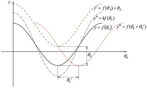
Figure shows a typical output variation of a four-bar mechanism and its transform. To find the relationship of the wavelet coefficients between the output, its translation and the dilation, y′ is obtained first by translating the output variation curve y to the upper region by θE units (i.e. y′ = y + θE). According to Equation (Equation3(3)
(3) ), the samples of y′ are:
(8)
(8)
Simplifying Equation (Equation8(8)
(8) ) yields:
(9)
(9)
where l = 0, 1, 2, …, 2j−1. Then, y′ can be approximated by the function :
(10)
(10)
According to Equation (Equation7(7)
(7) ),
can be decomposed into:
(11)
(11)
The value of and
can be described by:
According to Equation (Equation9(9)
(9) )
, then, the following relation holds:
Next, Equation (Equation11(11)
(11) ) can be written as follows:
(12)
(12)
Comparing Equation (Equation7(7)
(7) ) with Equation (Equation12
(12)
(12) ), it is shown that the translation of the output variation y on y-axis only changes the wavelet average and has no effect on the wavelet details.
Next, y″ is obtained by expanding y k times and defining y″ = ky. According to Equation (Equation3(3)
(3) ), the samples of y″ can be described as follows:
(13)
(13)
It is easy to find that . Then, y″ can be approximated as the function
, which yields:
(14)
(14)
According to Equation (Equation7(7)
(7) ), the decomposition of
gives:
(15)
(15)
Here, and
can be described as:
Then, Equation (Equation15(15)
(15) ) can be written as follows:
(16)
(16)
To determine the relationship of the wavelet coefficients between y and y″, a pre-process is applied to Equations (Equation6(6)
(6) ) and (Equation16
(16)
(16) ) to yield:
(17)
(17)
(18)
(18)
By comparing Equation (17) with (18), the coefficients are shown to have the same value.
Based on the analysis above, two conclusions are obtained as follows.
| (1) | For an arbitrary output of a four-bar mechanism, the y-axis translation only affects the wavelet average y0, and the change in y0 is equal to the function transform. | ||||
| (2) | For an arbitrary output of a planar slider–crank mechanism, if the bar length expands k times, then its output displacement wavelet coefficients also expand k times. Using a pre-process, the effects of a changing bar length on wavelet coefficients can be eliminated. | ||||
Finally, according to Equation (Equation3(3)
(3) ),
, which is the θ0-axis translation of the output, is a part of an independent variable; changes in
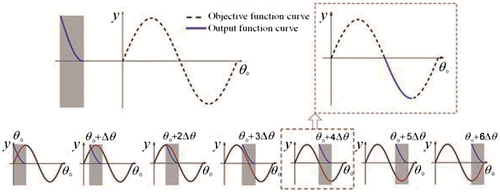
cannot be reflected by the wavelet coefficients. Thus, a method is proposed by scanning the integral period of the output from 0 to 2π to obtain the θ0-axis translation parameter. The required steps are shown in Figure ; the solid line is the objective function curve, the dotted line is the output curve of the four-bar mechanism that is scanned, and Δθ is the scanning step.
4. Verification of the two conclusions
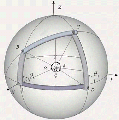
A spherical four-bar mechanism in a general position is shown in Figure ; the coordinate system has its origin at O. The mechanism has four links: frame AD, crank AB, coupler BC and driven link CD. The links can be regarded as arcs of great circles, and their lengths are equal to the angles subtended at the centre of the sphere: AB = α, BC = γ, CD = β, AD = ξ. The input angle of crank AB is θL; thus, the input–output angles for the mechanism can be described as follows:(19)
(19)
where ;
;
;
;
.
The size of each linkage is detailed as follows: α = 21°, γ = 55°, β = 47°, ξ = 61° and θL ∈ [0°, 90°]. For the computation of the output Haar wavelet transform, j = 6. Then, according to Eqs. (Equation3(3)
(3) –Equation7
(7)
(7) ), 64 wavelet coefficients of θ1 can be obtained. Due to the multi-resolution analysis property of the wavelet transform, the first eight wavelet coefficients (y0, w0, w1, …, w6) of the output were identified and defined as the wavelet feature parameters to approximate the prescribed function; this finding did not significantly affect the result, but reduced the computational burden. Then,
is obtained by translating θ1 to the upper region by three units. The first eight coefficients (y′0, w′0, w′1, …, w′6) were also identified as the feature parameters for the Haar wavelet transform. The two resulting groups of feature parameters are shown in Table ; note that these parameters are identical except in the wavelet approximation. According to the numerical relationship between y0 and y′0, the position relationship between θ1 and
can be determined to be 4.5016° − 1.5016° = 3°. Thus, the correctness of conclusion (1) is proved.
Table 1. Wavelet feature parameters of spherical four-bar mechanism output.
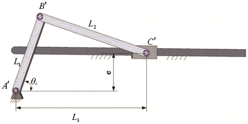
A general planar slider–crank mechanism is shown in Figure . L1, L2, θL and e are the length of the crank, the length of rod, the input angle and the offset value, respectively. According to the geometric relationships of this mechanism, the input–output equation for the slider–crank mechanism can be described as follows:(20)
(20)
The lengths L1, L2 and e are equal to 13, 42 and 6 mm, respectively; θL ∈ [45°, 180°]; and for the computation of the output Haar wavelet transform, j = 6, resulting in the feature parameter of L3. Then, the dilation of the linkage lengths results in L1 = 26 mm, L2 = 84 mm and e = 12 mm; the output is also shifted to the upper region by four units. With the same wavelet transform, another group of feature parameters can be obtained. The resulting two groups of feature parameters are shown in Table .
Table 2. Wavelet feature parameters of slider–crank mechanism output.
After applying the pre-process to these two groups, the results are shown in Table . The two groups feature parameters that are identical except in the wavelet approximation. According to the numerical relationship between the two groups in Table , the proportion and position relations between the two output displacement functions can be determined to be k = 12.4604/6.2302 = 2 and θE = 79.6532–37.8266 × 2 = 4 mm. Whether the experimental investigation is consistent with the hypothesis will either prove or disprove conclusions (1) and (2).
Table 3. Wavelet feature parameters after pre-process.
According to Equations (7)–(12) and (16), the shift parameter (θE) and the dilation parameter (k) can be calculated as follows:(21)
(21)
(22)
(22)
where y0, w0 and y′0, w′0 are the wavelet feature parameters of the prescribed function and its translation or dilation.
5. Establishment of a database and the steps of synthesis
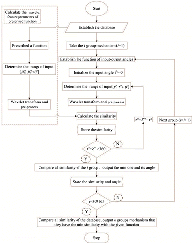
According to the above analysis, the relationship of the wavelet feature parameters between the output and all possible versions of dilation and translation can be obtained. Then, the effect can be eliminated by the pre-processing of the wavelet feature parameters. The three resulting databases that contain the linkage lengths and the input angles can be established and are composed of 203,500 groups of basic dimensional types of planar four-bar mechanisms, 148,995 groups of basic dimensional types of spherical four-bar mechanisms and 11,175 groups of basic dimensional types of planar slider–crank mechanisms. Based on the fuzzy recognition theory, similarity can be obtained by the following equation:(23)
(23)
where ap and are the wavelet feature parameters of the objective function and output variable, respectively. According to the similarity value between the prescribed function and each output of the four-bar mechanism in the database, the size of the required mechanism can be obtained. The specific step chart is shown in Figure , where
is the scanning step.
6. Determining the optimal algorithm
6.1. Optimization method
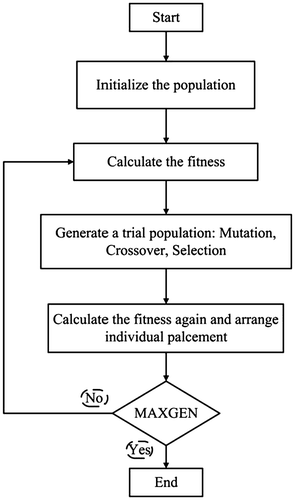
The dimensions of the database are discrete, which may indicate that a better solution may exist outside the database. To find this optimal solution, a genetic algorithm is used to optimize the result. Genetic algorithms are a method used in computing to find the approximate solutions to optimization problems by reducing error. It is a special class of evolutionary algorithms that use techniques inspired by evolutionary biology. At first, according to the given constraints, an initial population is generated, where each individual of the population is a possible solution to the synthesis problem. Next, the population evolves by natural selection, reproduction and mutation. Then, a new population where the individuals are better solutions is obtained. The above steps are then repeated until the termination criterion is satisfied. In this study, the maximum number of generations is limited to 200.
6.2. Optimization steps
6.2.1. Initialization of the population
A basic type of population of a four-bar mechanism is generated randomly as follows:(24)
(24)
where F represents the number of individuals, and rand(−1, 1) is a random number in (−1, 1) that is generated for each parameter. λq is the step size; for a four-bar linkage mechanism, when n = 1–4, λq is the step of establishing the dimensions of a database; when n = 5, λq is the scanning step of θ0-axis. For a planar four-bar mechanism, xn yields:(25)
(25)
For a spherical four-bar mechanism, xn yields:(26)
(26)
For a slider–crank mechanism, when n = 1–3, λq is the step of establishing the dimensions of a database; when n = 4, λq is the scanning step of θ0-axis, and xn yields:(27)
(27)
6.2.2. Calculating fitness
The fitness of an individual is defined by:(28)
(28)
where ap and represent the wavelet feature parameters of the prescribed function and the four-bar mechanism output. For a four-bar linkage mechanism, the optimization variables are defined as follows:
(29)
(29)
The optimization variables of a planar slider–crank mechanism only include L1, L2, e and .
6.2.3. Selection
In this study, the roulette wheel selection method is used to randomly choose two individuals from the population. Dependent on its fitness, each individual has a weight; the best individual has a higher opportunity to be chosen. The opportunity of the ith individual is prescribed by:(30)
(30)
6.2.4. Crossover
Then, the one-point crossover method is used to create two children from the parental individuals chosen by (3). The resulting children will have a higher fitness than the parental individuals. The crossover probability is equal to 0.08.
6.2.5. Mutation
Mutation is a genetic operator that randomly changes a gene during reproduction to maintain genetic diversity. In this study, when gene xF mutates, the genetic operator randomly chooses a value within the constraints.
After repeating the above steps, the sizes of the objective mechanisms, which are the minimum of δ(x), can be obtained. The steps of the genetic algorithm are shown in Figure as a process flow chart.
7. Examples
7.1. Theoretical example
To verify the validity of this method, an arbitrary group of basic dimensional types of four-bar mechanisms are chosen as a test mechanism; the output of the selected mechanism is then obtained. For the computation of the output Haar wavelet transform, a series of wavelet coefficients can be obtained. The wavelet feature parameters are then identified, their similarities with all of the basic dimensional types in the database are determined and several groups of basic dimensional types with minimal similarities are exported as the result. If the synthesis results contain the task mechanism, then the rationality of the synthesis method was proven. In the first example, the 83,914th group of basic dimensional types of spherical four-bar mechanisms was chosen as an example, where α, γ, β and ξ are equal to 17°, 35°, 57° and 73°, respectively, and θL ∈ [55°, 108°]. For the computation of the partial Haar wavelet transform, j = 6 and eight wavelet feature parameters of θ1 were obtained. Their similarities were then compared with all of the basic dimensional types in the database; ten groups of basic dimensional types with minimal similarity were exported as the result, as shown in Table . The seventh group showed the lowest similarity (sdn = 0) and was exported as the result. When α, γ, β, ξ, and θE are equal to 17°, 35°, 57°, 73°, 55° and 0°, respectively, it is fully consistent with the data of this study.
Table 4. Comprehensive results of a spherical four-bar mechanism.
7.2. Comparison example
In this early work, we found that the existing numerical atlas methods are appropriate for periodic function synthesis; they can guarantee high accuracy along the entire function curve. For example, a spherical four-bar linkage can be synthesized by the function in [Citation26] with:
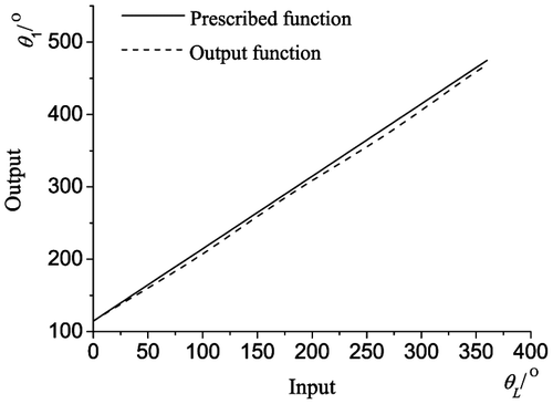
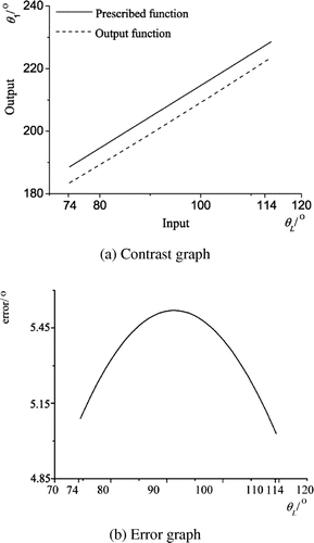
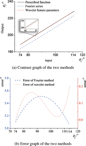
Using the Fourier series method, ten groups of basic dimensional types are obtained from the numerical atlas, and the actual dimensions of the mechanisms are listed in Table , where Q is the initial angle of the driving crank. The prescribed and output function of the second group of spherical four-bar linkages is shown in Figure . It can be seen from Figure that the synthesis results have a high accuracy throughout the interval; however, when 74° ≤ θL ≤ 114°, the margin of error is wide (see the comparison and error graphs in Figure ). Using the method proposed in this study, the previous example can be synthesized to generate the same function, with an input angle of 74° ≤ θL ≤ 114°. These synthesis results are shown in Table . The generated function graphs with the wavelet feature parameters method (i.e. the first group’s results), the Fourier series method and each method’s error is provided in Figure , where the black solid line is the prescribed function curve, the dotted line is the function curve generated by the Fourier series method and the dot-dash line is the function curve generated by the wavelet feature parameters method. These synthesis results of the wavelet feature parameters method are shown to be more accurate.
Table 5. Actual dimensions of the mechanisms for comparison example.
Table 6. Synthesis results using the wavelet method.
7.3. Practical example
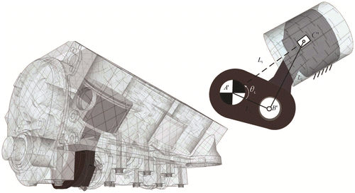
In this example, a planar slider–crank mechanism in a piston engine is designed (see Figure ). The prescribed function is L3 = 20 + 40cos(θL) + 10sin(2θL), where the input angle is θL ∈ [43°, 86°], and e = 0 mm.
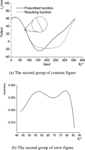
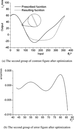
Based on the wavelet theory, the wavelet feature parameters of the prescribed function are obtained and are shown in Table . After applying the pre-process to the feature parameters (see Table ) and comparing their similarities with all of the output basic dimensional types in the slider–crank mechanism numerical atlas database, ten groups of basic dimensional types with minimal similarity were obtained according to their similarity values and are shown in Table . The comparison and error graphs of the second group are shown in Figure , where the solid and dotted lines represent the prescribed and resulting functions, respectively. The optimization results of the second group are shown in Table , and the comparison and error graphs of the second group are shown in Figure .
Table 7. Wavelet feature parameters of prescribed function.
Table 8. Wavelet feature parameters after pro-process.
Table 9. Comprehensive results.
Table 10. Optimization results of the comprehensive examples.
8. Conclusions
| (1) | In this study, a mathematical model for the output of a four-bar mechanism is established. A wavelet descriptor for the output of a four-bar mechanism is developed according to the wavelet transform. The relationship of the wavelet feature parameters between the four-bar mechanism output and its translation or dilation is also discovered. Based on this relationship, a large number of atlas databases, which include planar, spherical and planar slider–crank mechanisms, are established. | ||||
| (2) | Using the relationship of Haar wavelet feature parameters between the objective function and the output of a four-bar mechanism, the recognition method is presented for the objective mechanism, allowing the size of the required mechanism to be obtained. Then, the non-integer periodic function synthesis of four-bar mechanism can be obtained. | ||||
| (3) | By solving problem of non-linear equations is avoided, which the function generation problem can be easily solved and the method overcomes the deficiency where the Fourier series method cannot describe non-integer periodic functions accurately. The mechanical solutions can be found out quickly and accurately from the numerical atlas database, and at the same time, the more solutions and larger choosing freedoms are offered to users. | ||||
| (4) | The method proposed in this study is also effective for other types of single degree of freedom (DOF) mechanisms. Based on wavelet series theory, the non-integer periodic function generation problem of linkage mechanisms and the non-integer periodic path generation problem of single-DOF planar mechanisms can be realized. At present, we have realized the features extraction of the coupler curve for planar four-bar linkages. In the future, we aim to establish a unified method for the dimensional synthesis of linkage mechanisms. | ||||
Disclosure statement
No potential conflict of interest was reported by the authors.
Additional information
Funding
References
- Freudenstein F. Approximate synthesis of four-bar linkages. Trans. ASME. 1955;77:853–861.
- Bai S, Angeles J. A unified input–output analysis of four-bar linkages. Mech. Mach. Theor. 2008;43:240–251.10.1016/j.mechmachtheory.2007.01.002
- Suixian Y, Hong Y, Tian GY. Optimal selection of precision points for function synthesis of spherical 4R linkage. IMechE Part C J. Mech. Eng. Sci. 2009;233:2183–2189.
- Alizade RI, Özgür K. Analytical synthesis of function generating spherical four-bar mechanism for the five precision points. Mech. Mach. Theor. 2005;40:863–878.
- Alizade RI, Gezgin E. Synthesis of function generating spherical four bar mechanism for the six independent parameters. Mech. Mach. Theor. 2011;46:1316–1326.10.1016/j.mechmachtheory.2011.04.002
- Singh S, Mehar R. Optimal synthesis of four-bar mechanism for function generation with five accuracy points. Inverse Probl. Sci. Eng. 2015;23:1222–1236.
- Buśkiewicz J. A method for optimal path synthesis of four-link planar mechanisms. Inverse Probl. Sci. Eng. 2015;23:818–850.10.1080/17415977.2014.939654
- Russell K, Sodhi RS. Kinematic synthesis of RRSS mechanisms for multi-phase motion generation with tolerances. Mech. Mach Theor. 2002;37:279–294.10.1016/S0094-114X(01)00064-7
- Shen Q, Russell K. On cam system design to replicate spatial four-bar mechanism coupler motion. Inverse Prob. Sci. Eng. 2011;19:251–265.10.1080/17415977.2010.550047
- Russell K, Shen Q. Expanded spatial four-link motion and path generation with order and branch defect elimination. Inverse Prob. Sci. Eng. 2013;21:129–140.10.1080/17415977.2012.672418
- Francisco T, Marin S, Gonzalez AP. Open-path synthesis of linkages through geometrical adaptation. Mech. Mach. Theor. 2004;39:943–955.
- Fang WE. Simultaneous type and dimensional synthesis of mechanisms by genetic algorithms. Mech. Synth. Anal. 1994;70:35–41.
- Shiakolas PS, Koladiya D, Kebrle J. On the optimum synthesis of four-bar linkages using differential evolution and the geometric centroid of precision positions. Inverse Prob. Eng. 2002;10:485–502.10.1080/1068276021000054594
- Peñuñuri F, Peón-Escalante R, Villanueva C, Pech-Oy D. Synthesis of mechanisms for single and hybrid tasks using differential evolution. Mech. Mach. Theor. 2011;46:1335–1349.
- Matekar SB, Gogate GR. Optimum synthesis of path generating four-bar mechanisms using differential evolution and a modified error function. Mech. Mach. Theor. 2012;52:158–179.10.1016/j.mechmachtheory.2012.01.017
- Mirmahdi SH, Norouzi M. On the comparative optimal analysis and synthesis of four-bar function generating mechanism using different heuristic methods. Meccanica. 2013;48:1995–2006.10.1007/s11012-013-9718-7
- Svobada A. Computing mechanism and linkages. New York (NY): McGraw-Hill; 1948.
- Hrones JA, Nelson GL. Analysis of the four-bar linkage. New York (NY): MIT Press and Wiley; 1951.
- Nie XC, Krovi V. Fourier methods for kinematic synthesis of coupled serial chain mechanisms. J. Mech. Des. 2005;127:232–241.10.1115/1.1829726
- Mullineux G. Atlas of spherical four-bar mechanisms. Mech. Mach. Theor. 2011;46:1811–1823.10.1016/j.mechmachtheory.2011.06.001
- Yu H, Tang D, Wang Z. Study on a new computer path synthesis method of a four-bar linkage. Mech. Mach. Theor. 2007;42:383–392.10.1016/j.mechmachtheory.2006.05.003
- Wang Z, Yu H, Tang D, Li J. Study on rigid-body guidance synthesis of planar linkage. Mech. Mach Theor. 2002;37:673–684.10.1016/S0094-114X(02)00014-9
- Sun J, Lu H, Chu J. Variable step-size numerical atlas method for path generation of spherical four-bar crank–slider mechanism. Inverse Prob. Sci. Eng. 2015;23:256–276.10.1080/17415977.2014.890615
- Yue C, Su HJ, Ge QJ. A hybrid computer-aided linkage design system for tracing open and closed planar curves. Comput. Aided Des. 2012;44:1141–1150.10.1016/j.cad.2012.06.004
- McGarva JR, Mullineux G. A new methodology for rapid synthesis of function generators. IMechE Part C J. Mech. Eng. Sci. 1992;206:391–398.10.1243/PIME_PROC_1992_206_146_02
- Sun J, Chu J. Synthesis of spherical four-bar function generator by means of Fourier method. 12th IFToMM World Congress; 2007 June 18–21; Besançon, France.
- Wu X, Chu J, Cao W. Analysis of output function of 4-bar linkages using wavelet transform. Mech. Sci. Technol. 1998;17:180–186.
- Wang C, Ji J. Research on applying wavelet analysis to path synthesis for coupler curves of planar four-bar linkages. Chin. J. Mech. Eng. 2004;40:34–39.
- Galán-Marín G, Alonso FJ, Del Castillo JM. Shape optimization for path synthesis of crank–rocker mechanisms using a wavelet-based neural network. Mech. Mach. Theor. 2009;44:1132–1143.10.1016/j.mechmachtheory.2008.09.006
- Daubechies L. Ten lectures on wavelet. Philadelphia (PA): Society for Industrial and Applied Mathematics; 2001.

