 ?Mathematical formulae have been encoded as MathML and are displayed in this HTML version using MathJax in order to improve their display. Uncheck the box to turn MathJax off. This feature requires Javascript. Click on a formula to zoom.
Abstract
This paper presents novel approach to structural damage detection and estimation using incomplete static responses of a damaged structure and least squares support vector machine (LS-SVM). The presented method is based on the reduced stiffness matrix to formulate incomplete static responses as input parameters to the LS-SVM. The presented method is applied to a plane steel bridge, a four-span continuous beam and four-storey plane frame containing several damages. Also, the effect of the discrepancy in stiffness between the finite element model and the actual tested system has been investigated. The results show that the presented method is sensitive to the location and severity of the structural damage in spite of the incomplete noisy data and modelling errors.
1. Introduction
Structural damage detection in civil and mechanical engineering structures during their service life has drawn wide attention during the last few decades. In recent years, many damage detection and estimation methods have been proposed based on the changes of dynamic characteristics and static responses.[Citation1–5] Static damage identification methods are usually simple and the equipment of static testing, and precise static displacements of structures could be obtained rapidly and economically.[Citation1] Therefore, these methods have attracted much attention in the civil engineering field.[Citation6]
Wang et al. [Citation7] presented an improved interval analysis technique based on the measured static displacements for the structural damage identification. The numerical example shows that the wide intervals resulting from the interval operation can be narrowed by the improved non probabilistic approach. Also, Abdo [Citation8] studied the relationship between damage characteristics (location and severity) and changes in displacement curvatures. The numerical results clarify that the displacement curvature has the characteristic of localization at the damaged region. Recently, Viola et al. [Citation9] presented an approach to parametric system identification and damage detection in truss structures by static tests. A novelty introduced by the proposed technique is the ability to take into account plane and three-dimensional structures when only a partial set of measurements is available.
The least squares support vector machine (LS-SVM) is an advanced version of the standard SVM, which was first introduced by Suykens et al. [Citation10]. LS-SVM has been widely used in different fields of engineering as robust and promising method for classification and function estimation. Xie [Citation11] studied fuzzy least square support vector machine (FLS-SVM) combining Fuzzy Logic with LS-SVM, and a real-coded quantum genetic algorithm (QGA) is applied to optimize parameters of FLS-SVM. Then, the method of FLS-SVM integrated QGA is used to detect damages for fibre smart structures. The proposed method of FLS-SVM integrated QGA is effective and efficient for structural damage detection. In other work, Xie [Citation12] developed improved LS-SVM combined with Hilbert transform to extract the characteristics of monitoring signals and detect damage locations for the composite laminated plate. Also, Tang et al. [Citation13] proposes an online sequential weighted LS-SVM technique to identify the structural parameters and their changes when vibration data involve damage events. The proposed method is capable of tracking abrupt or slow time changes of the system parameters from which the damage event and the severity of the structural damage can be detected and evaluated.
In this paper, a novel approach for localizing and estimating the severity of structural damage is introduced. The damage identification is carried out through training LS-SVM derived from incomplete static characteristics of damaged structure. Numerical examples show that the proposed method can be considered as a flexible and robust approach in damage identification of structures.
2. Proposed method
In this section, the proposed method for structural damage detection and estimation are illustrated. First, the model reduction method is formulated. Then, the LS-SVM is presented.
2.1. Model reduction method
The static equilibrium equation of a structure in a displacement based finite element frame work can be expressed as follows:(1)
(1)
where Kud, F and x are undamaged stiffness matrix, the force and displacement vectors, respectively.
One of the simplest techniques to determine damage-induced alteration stiffness is the degradation in Young’s modulus of an element as follows [Citation14]:(2)
(2)
where, and
are the damaged and undamaged Young’s modulus of the jth element in the finite element model, respectively, and dj indicates the damage severity at the jth element in the finite element model whose values are between 0 for an element without damage and 1 for a ruptured element.
From Equation (1), the static equilibrium equation of a damaged structure can be obtained as:
(3)
(3)
where, superscript d is noted as the damage state. As the number of sensors used to measure static responses is normally limited and usually is less than the number of DOFs in the finite element model, the model reduction method should be used to match with incomplete measured static responses. In fact, not all displacements in xd can be measured. Therefore, Equation (3) is partitioned into the master and slave coordinates as bellow:(4)
(4)
where, the subscripts m and s are the master and slave coordinates, respectively. The vector of slaved displacements is condensed out, following static condensation and Equation (3) reduces to the following:
(5)
(5)
and(6)
(6)
where:(7)
(7)
(8)
(8)
in which, and Fr are the condensed stiffness matrix and the condensed load vector of damaged structure; respectively.
2.2. Least squares support vector machine
Support vector machines (SVM) is a powerful methodology for solving the problems of nonlinear classification, regression, pattern recognition and function estimation.[Citation15] The LS-SVM is an advanced version of the standard SVM which applies the linear least squares criteria to the loss function instead of inequality constraints.[Citation10]
The LS-SVM model for regression relates inputs xi with the output yi and can be described as [Citation16]:(9)
(9)
where w denotes the weight vector, and b denotes the error and γ is the regularization parameter, and ei is the slack variable.
Eliminating the variables w and ei, the optimization problem can be transformed into the following linear solution:(10)
(10)
Where . According to the Mercer’s condition, the Kernel function can be set as:
(11)
(11)
Then, the LSSVM model for regression becomes:(12)
(12)
The RBF is a common option for the kernel function because of fewer parameters that need to be set and an excellent overall performance.[Citation17] Therefore, this study selected the RBF as the kernel function:(13)
(13)
Consequently, there are two parameters that need to be chosen in the LSSVM model, which are the bandwidth of the Gaussian RBF kernel σ and the regularization parameter γ. Hyper-parameters (σ2, γ) have a great influence on the performance of the resulting LS-SVM.
Coupled simulated annealing (CSA) [Citation18] and standard simplex method using 10-fold cross validation techniques are adopted to determine the optimal tuning parameters in the LS-SVM models. 10-fold cross-validation hyper-parameter selection procedure trains a LS-SVM 10 times for each set of candidate hyper parameters, and then selects the set of hyper-parameters yielding the best average performance on the corresponding 10 validation sets.[Citation19]
The complete tuning process goes as follows: first, for every kernel, first CSA determines suitable starting points for simplex method. The search limits of the CSA method are set to [exp(−10), exp(10)]. Second, these starting points are passed to the simplex method in order to fine tune the result. CSA have already proven to be more effective than multi start gradient descent optimization. Another advantage of CSA is that it uses the acceptance temperature to control the variance of the acceptance probabilities with a control scheme. This leads to improved optimization efficiency because it reduces the sensitivity of the algorithm to the initialization parameters while guiding the optimization process to quasi-optimal runs.[Citation20]
For Gaussian kernel LS-SVM, the choice of the kernel parameter affects the resulting LS-SVM significantly. A small
leads to overfitting while a big
may cause the classifier output similar values for all inputs and hence fail in the prediction of future samples. On the other hand, the penalty parameter
controls the trade-off between the margin and the training error.[Citation19]
In this paper, the static responses of a damaged structure are used as the input patterns. In this study, the LS-SVM method has been used for structural damage detection and estimation based on incomplete static responses. The proposed method uses the incomplete static responses as the input parameters to train the LS-SVM model. In this paper, the LS-SVMlab1.8 code package [Citation21] was added into the Matlab toolbox,[Citation22] which used the interface provided by LSSVM to realize the regression function.
Figure shows the flow chart of the proposed method for damage detection and estimation in structural elements.
3. Numerical examples
In this section, the efficiency and effectiveness of the proposed methods are evaluated through some numerically simulated damage identification tests using incomplete static responses. A plane steel bridge, four-span continuous beam and four storey plane frame are chosen with three different scenarios of damage for each of them for the purpose.
3.1. Plane steel bridge
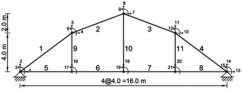
A plane steel bridge proposed by Kourehli et al. [Citation5] as illustrated in Figure with finite-element model consisting of elements 1–4 as beam-column elements; 5–8 as beam elements and 9–11 as column elements are considered. The numerical studies are carried out within the MATLAB [Citation22] environment, which is used for the solution of finite element problems. The uniformly distributed load 50 kN/m at the beam elements has been used. For the considered steel bridge, the material properties of the steel include Young’s modulus of E = 200 GPa. The cross-sectional area of the columns is: A = 150 × 10−4 m4. The moment of inertia and cross-sectional area of the beam-columns are: I = 189813.3 × 10−8 m4 and A = 280 × 10−4 m2, respectively. The moment of inertia of the beams is: I = 189813.3 × 10−8 m4.
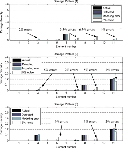
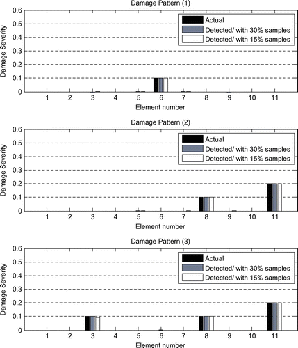
The three damage patterns for this case are:
| (1) | The damage severity of element 6 is 0.1. | ||||
| (2) | The damage severity of elements 8 and 11 are 0.1 and 0.2, respectively. | ||||
| (3) | The damage severity of elements 3, 8 and 11 are 0.1, 0.1 and 0.2, respectively. | ||||
In this case, only the last nine DOFs of bridge are selected as measured DOFs in the process of damage detection and quantification. To generate the training patterns, a number of structures with different static responses, using damage severity equal to 0, 10% and 0, 10, 20% for elements numbered 1, 3, 5, 7, 9, 11 and elements numbered 2, 4, 6, 8, 10, respectively, were considered, and their responses were computed using the numerical analyses. The total number of combinations of the assigned damage severities is 26 × 35 = 15,552.
The results were used for training patterns. After training, the mean-square error (MSE) and Correlation coefficient (R) of the measured and predicted damage severity values are determined as bellow:(14)
(14)
(15)
(15)
in which, Ai and Bi represent the measured and modelling damage severity values, while and
denote the mean of the measured and predicted values, respectively; N represents the number of data sample. The Correlation coefficient (R) indicates the correlation between the outputs and targets. A Correlation coefficient (R) value of unity means a close relationship and zero a random relationship. The Mean Squared Error is the average squared difference between the outputs and targets, with lower values on the better side.
To investigate the performance of the proposed method, two different sample numbers equal to 30 and 15% samples are used for training. It should be noted that the method used for selecting sample numbers is trial and error, in which the less used sample numbers may have more errors. Also, the obtained hyperparameters for different sample numbers for training are summarized in Table .
Table 1. Obtained hyperparameters for plane steel bridge with different sample numbers.
Table shows the LS-SVM performance in training and testing stages for plane steel bridge with different sample numbers. Testing has no effect on training and so provides an independent measure of network performance during and after training [Citation23]. According to Table , the Correlation coefficient (R) values are close to unity using 30% samples that means a close relationship between the outputs and targets. The MSE values are very low that means minimum average squared difference between the outputs and targets. Also, it can be seen that the performance of the proposed method using 15% samples is acceptable.
Table 2. Statistics for training and testing for plane steel bridge with different sample numbers.
Figure shows the results of damage identification in the plane steel bridge for considered damage scenario with different sample numbers. The obtained results indicate that the proposed method is robust and promising in detecting and quantifying various damage patterns with fewer samples for training. The results using 15% randomly selected samples are good. For this case (15% samples), inputs xi is a matrix with 2332 rows (number of samples for training) and 9 columns (9 translational measured DOFs) and output yi is a matrix with 2332 rows (number of samples for training) and 11 columns (11 structural elements).
Figure 3. Results for three damage patterns of the plane steel bridge with fewer samples for training.
To be more suited with the real cases, an examination has been performed in which the measured displacements of damaged structure with 5% noise are utilized for damage identification considering the same patterns mentioned before. To perform this, some random noise has been added to the theoretically calculated measured displacements. The contaminated displacement with noise can be obtained from the displacement without noise using the following equation:(16)
(16)
where and
are the measured displacements of damaged structure contaminated with noise and without noise, respectively. β is the noise level (e.g., 0.05 relates to a 5% noise level) and rand is a random number in the range [–1 1].
Also, the modelling errors in the analytical model have been studied using the following equation:(17)
(17)
where is the stiffness matrice of the jth element in the finite element model with perturbations of stiffness
. In the plane steel bridge, it is assumed that the actual tested bridge has perturbations of stiffness of 3 and 2% at elements 3 and 11; respectively.
Figure shows the results of damage identification in the plane steel bridge for the considered damage scenario with 15% randomly selected samples for training. The results illustrate that the proposed method is a robust and effective method in detecting and quantifying various damage scenario in spite of incomplete static responses which may be noisy or noise free. It can be seen that the damage severity and locations can be obtained for the various damage patterns considering the modelling errors. Although some undamaged elements are detected as damage by mistake in which value of damage is low, the damaged elements are properly detected with correct value of severity.
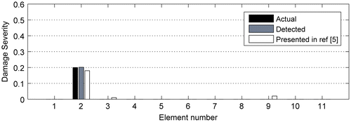
Also, the performance of the proposed damage detection and estimation method is validated thorough the obtained result presented by Kourehli et al. [Citation5]. Figure provides comparison between the obtained results from the presented method in this paper and pattern search algorithm (PS) method proposed by Kourehli et al. [Citation5]. As it is shown, the damage severity and location obtained by both the methods are close to actual damages. Also, it should be noted that the proposed method is more accurate.
3.2. Four-span continuous beam
A four-span continuous beam as illustrated in Figure with a finite-element model consists of 11 beam elements and 12 nodes are considered. For the considered concrete beam, the material properties include Young’s modulus of E = 25 GPa and mass density of ρ = 2500 kg/m3. The cross-sectional area and the moment of inertia of the beam are: A = 0.35 m2 and I = 0.01429 m4. Also, the three damage patterns for this case are:
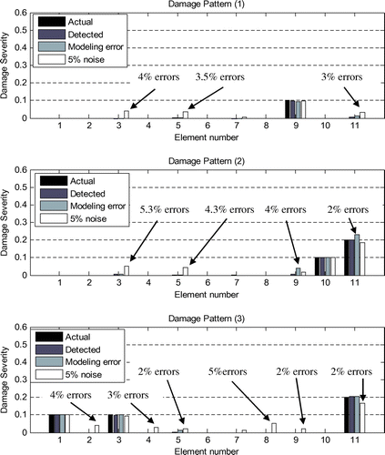
| (1) | The damage severity of element 9 is 0.1. | ||||
| (2) | The damage severity of elements 10 and 11 are 0.1 and 0.2, respectively. | ||||
| (3) | The damage severity of elements 1, 3 and 11 are 0.1, 0.1 and 0.2, respectively. | ||||
In this case, only the first nine DOFs are selected as measured DOFs in the process of damage detection and quantification. To generate the training patterns, a number of structures with different static responses, using damage severity equal to 0, 10% and 0, 10, 20% for elements numbered 1,3,5,7,9,11 and elements numbered 2,4,6,8,10, respectively, were considered, and their responses were computed using the numerical analyses. The total number of combinations of the assigned damage severities is 26 × 35 = 15,552. In this example, 15% randomly selected samples were used for training. Also, the obtained hyperparameters for different sample numbers for training are summarized in Table .
Table 3. Obtained hyperparameters for the four-span continuous beam.
According to Table , the low value of MSE and high value of R were achieved using the proposed method. Also, the modelling errors in the analytical model have been investigated. It is assumed that the actual tested beam has perturbations of stiffness of 3 and 2% at elements 4 and 10, respectively.
Table 4. Statistics for training and testing for four-span continuous beam.
Figure shows the capability of the proposed method for detection and quantification of the damage using incomplete static responses which may be noisy or noise free. The obtained results indicated that the proposed method can be characterized as a robust and viable method for damage detection and quantification of structures considering the modelling errors. Also, the results show that the proposed method is not sensitive to modelling errors in some elements.
3.3. Four-storey plane frame
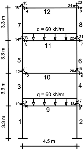
A four-storey plane steel frame as illustrated in Figure with finite-element model consists of 12 elements (eight columns and four beams) and 8 free nodes are considered. For the considered steel frame, the Young’s modulus E = 200 GPa. The moment of inertia, and cross-sectional area of the columns are: I = 3.3 × 10⁻⁴ m4 and A = 1.5 × 10⁻² m2, respectively; for the beams are: I = 3.69 × 10⁻⁴ m4 and A = 1.52 × 10⁻² m2. Also, the three damage patterns for this case are:
| (1) | The damage severity of element 12 is 0.1. | ||||
| (2) | The damage severity of elements 4, 8 are 0.2, 0.1, respectively. | ||||
| (3) | The damage severity of elements 5, 7 and 12 are 0.1, 0.2 and 0.1, respectively. | ||||
The master DOFs consist of the first 12 DOFs in the process of damage detection and quantification. To generate the training patterns, a number of structures with different static responses, using damage severity equal to 0, 10, 20% and 0, 10% for elements numbered 1,4,7,10,12 and elements numbered 2,3,5,6,8,9,11, respectively were considered, and their responses were computed using the numerical analyses. The total number of combinations of the assigned damage severities is 35 × 27 = 31,104. In this example, 7% randomly selected samples were used for training. Also, the obtained hyperparameters for different sample numbers for training are summarized in Table .
Table 5. Obtained hyperparameters for four-storey frame.
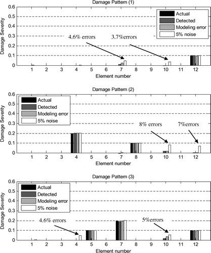
According to Table , the low value of MSE and high value of R achieved using the proposed method. Also, it is assumed that the actual tested frame has perturbations of stiffness of 2 and 3% at elements 11 and 10, respectively.
Table 6. Statistics for training and testing for four-storey frame.
Figure shows the identified damaged elements using the proposed method. It can be seen that the damage severity and locations can be obtained for three different patterns in spite of incomplete noisy data and modelling errors. Although in the case of noisy data some undamaged elements are detected as damaged by mistake.
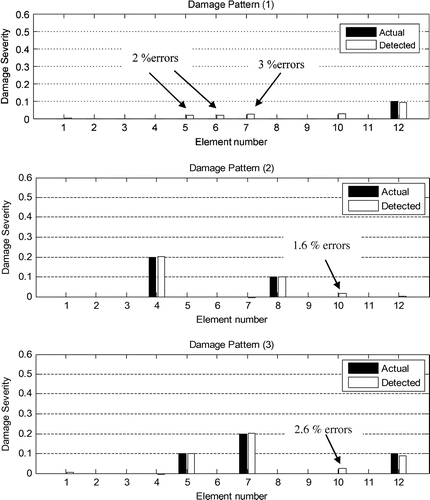
Another examination has been performed using the first nine DOFs as a measured data. Table shows the LS-SVM performance in training and testing stages using fewer master DOFs.
Table 7. Statistics for training and testing for four-storey plane steel frame using fewer master DOFs.
Also, Figure shows the identified damaged elements using the proposed method using fewer master DOFs. The obtained results show that some undamaged elements are detected as damaged by mistake.
4. Conclusions
In this paper, an effective method for structural damage detection and estimation using incomplete static responses and LS-SVM was presented. The static Guyan reduction method is used to condense stiffness matrix. The presented method uses the incomplete static responses as the input parameters to train the LS-SVM model.
The proposed method is applied to three different problems, namely a plane steel bridge, four-span continuous beam and four-storey plane frame containing one or several damage patterns. The obtained results revealed high sensitivity of the proposed method to detect and estimate damage in spite of incomplete noisy measurements and modelling errors.
Funding
This work was supported by the Ahar Branch, Islamic Azad University
Disclosure statement
No potential conflict of interest was reported by the author.
Acknowledgement
The author would like to thank Ahar Branch, Islamic Azad University for the financial support of this research, which is based on a research project contract.
References
- He RS, Hwang SF. Damage detection by a hybrid real-parameter genetic algorithm under the assistance of grey relation analysis. Eng. Appl. Artif. Intell. 2007;20:980–992.10.1016/j.engappai.2006.11.020
- Kourehli SS. LS-SVM regression for structural damage diagnosis using the iterated improved reduction system. Int. J. Struct. Stab. Dy. 2016;16:1550018. doi:10.1142/S0219455415500182.
- Kourehli SS. Damage assessment in structures using incomplete modal data and artificial neural network. Int. J. Struct. Stab. Dyn. 2015;15:1450087. doi:10.1142/S0219455414500874.
- Rasouli A, Ghodrati Amiri G, Kheyroddin A, et al. A new method for damage prognosis based on incomplete modal data via an evolutionary algorithm. Eur. J. Environ. Civil Eng. 2014;18:253–270.10.1080/19648189.2014.881758
- Kourehli SS, Bagheri A, Ghodrati Amiri G, et al. Structural damage identification method based on incomplete static responses using an optimization problem. Sci. Iran. 2014;21:1209–1216.
- Wang X, Hu N, Fukunaga H, et al. Structural damage identification using static test data and changes in frequencies. Eng. Struct. 2001;23:610–621.10.1016/S0141-0296(00)00086-9
- Wang X, Yang H, Wang L, et al. Interval analysis method for structural damage identification based on multiple load cases. J. Appl. Mech. 2012;79:051010.10.1115/1.4006447
- Abdo MAB. Parametric study of using only static response in structural damage detection. Eng. Struct. 2012;34:124–131.10.1016/j.engstruct.2011.09.027
- Viola E, Bocchini P. Non-destructive parametric system identification and damage detection in truss structures by static tests. Struct. Infrastruct. Eng. 2013;9:384–402.10.1080/15732479.2011.560164
- Suykens JAK, Vandewalle J. Least squares support vector machine classifiers. Neural Process. Lett. 1999;9:293–300.10.1023/A:1018628609742
- Xie JH. Structural damage detection based on fuzzy LS-SVM integrated quantum genetic algorithm. Appl. Mech. Mater. 2010;20:1365–1371.10.4028/www.scientific.net/AMM.20-23
- Xie J. Improved least square support vector machine for structural damage detection. Neural Comput. 2010;6:V6-237–V6-240.
- Tang HS, Xue ST, Chen R, et al. Online weighted LS-SVM for hysteretic structural system identification. Eng. Struct. 2006;28:1728–1735.10.1016/j.engstruct.2006.03.008
- Szewczyk ZP, Hajela P. Damage detection in structures based on feature-sensitive neural networks. J. Comput. Civil Eng. 1994;8:163–178.10.1061/(ASCE)0887-3801(1994)8:2(163)
- Cristianini N, Shawe-Taylor J. An introduction to support vector machines. Cambridge: Cambridge University Press; 2000.
- Suykens JAK, Van Gestel T, De Brabanter J, et al. Least squares support vector machines. Singapore: World Scientific; 2002.
- Keerthi SS, Lin CJ. Asymptotic behaviors of support vector machines with Gaussian Kernel. Neural Comput. 2003;15:1667–1689.10.1162/089976603321891855
- Xavier-de-Souza S, Suykens JA, Vandewalle J, et al. Coupled simulated annealing. IEEE Trans. Syst. Man Cybernet. Part B. 2010;40:320–335.10.1109/TSMCB.2009.2020435
- Sun B, Ng WW, Yeung DS, et al. Hyper-parameter selection for sparse LS-SVM via minimization of its localized generalization error. Int. J. Wavelets Multiresolut. Inf. Process. 2013;11:1350030.10.1142/S0219691313500306
- De Brabanter K, Karsmakers P, Ojeda F, et al. LS-SVMlab toolbox user’s guide. Leuven: ESAT-SISTA Technical Report; 2011. p. 10–146.
- Available from. http://www.esat.kuleuven.be/sista/lssvmlab/.
- MATLAB. Matlab user manual. Lowell (MA): Mathwork ; 2013.
- Rumelhart DE, McClell JL. Parallel distributed processing, foundations. Vol. 1. Cambridge, MA: MIT Press; 1986.


