
 ?Mathematical formulae have been encoded as MathML and are displayed in this HTML version using MathJax in order to improve their display. Uncheck the box to turn MathJax off. This feature requires Javascript. Click on a formula to zoom.
Abstract
Identification of high-magnitude heat flux in real time is a challenging problem, since most of the currently available algorithms require large computation time in comparison with the time scale of the real physical problem. This paper presents a methodology that allows for quantifying the unsteady heat flux in real time by using the steady-state Kalman filter. Two different cases have been used to verify this algorithm and the estimates are in excellent agreement with the reference values.
1. Introduction
In many practical problems it is desirable to detect an external excitation and/or control an unsteady process when only indirect measurements of the variables of interest are available. The estimation process of the control variables needs to be performed sequentially, i.e. each measurement must be processed at the moment that it is acquired. Regretfully, even with currently affordable powerful computers, the computational time for such inverse problems is usually much larger than the time interval between two consecutive measurements and online detection/control is not possible. One example of how online estimation can still be a computationally challenging problem, is the identification of a locally applied unsteady high-magnitude heat flux in three-dimensional heat conduction problems by using nonintrusive temperature measurements taken over another boundary.
Previous attempts to solve this problem by using several different methods can be found in the literature.[Citation1–Citation9] Although these authors successfully estimated the unknown variable, a big challenge is still to perform the estimation process quick enough so that the heat flux can be identified in real time. In this work, the so-called steady-state Kalman filter (SSKF) [Citation10] is applied to the same inverse problem examined in Refs. [Citation5–Citation7] where the regular Kalman filter (KF) was used. The main objective of this paper is the reduction of the computational time required for the application of the KF, aiming at the online identification of a boundary heat flux applied on a plate, as described next.
2. Complete and reduced models
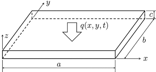
An isotropic flat plate of uniform thickness (Figure ) is considered in this work. A spatially and time varying heat flux of large magnitude, q(x, y, t), is imposed on the surface , while the remaining boundaries are considered as thermally insulated. The initial temperature distribution is considered as uniform. The mathematical model for this three-dimensional problem is first presented, in which nonlinearities due to temperature dependence of the thermophysical properties are taken into account, because temperature gradients in the region are very large.[Citation4–Citation7] The mathematical formulation for this three-dimensional nonlinear heat conduction problem is hereafter referred to as the complete model. A reduced model is then derived, based on simplifications of this three-dimensional model, which readily enables the application of the KF for the solution of the inverse problem that is considered in this work. The inverse problem deals with the estimation of the applied heat flux q(x, y, t) at
by using temperature measurements taken over the surface
.
Figure 1. Geometry of the physical domain.
2.1. Complete model
The complete model is given by the following unsteady, three-dimensional and nonlinear heat conduction problem:(1)
(1)
(2a)
(2a)
(2b)
(2b)
(2c)
(2c)
(2d)
(2d)
(2e)
(2e)
The dependence of the thermal properties with temperature is given by [Citation4,Citation11]:(3a)
(3a)
(3b)
(3b)
The forward (direct) problem given by Equations (Equation1(1)
(1) ) and (2), where the thermophysical properties, initial and boundary conditions are known, can be solved by several numerical techniques. However, due to the nonlinear nature of this three-dimensional problem, performing an inverse analysis would require a large computational effort. In order to avoid this difficulty another forward problem, based on the complete model given by Equations (Equation1
(1)
(1) ) and (2) and called reduced model, was derived and used in the inverse analysis as illustrated below.
2.2. Reduced model
The reduced model used in this work was obtained from the complete model given by Equations (Equation1(1)
(1) ) and (2) in three steps,[Citation4–Citation7] as follows. The first step involves the linearization of the problem, by replacing the temperature-dependent thermal properties by constant ones. The values of these constant properties were obtained by evaluating Equations (Equation3a
(3a)
(3a) ) and (Equation3b
(3b)
(3b) ) at reference temperature
K, i.e.
(4a)
(4a)
(4b)
(4b) The use of constant thermophysical properties, such as given by Equation (4) allows the partial lumping across the thickness of the plate. The temperature value used for evaluating the thermophysical properties is the same used in [Citation4–Citation7].
The second step deals with reducing the number of dimensions of the problem. The average temperature in the z-direction is introduced in the analysis by the following operation over the temperatures
, obtained from the linearized version of the complete model (i.e. the complete model with constant thermal properties, proposed in Equation (4)),
(5)
(5)
thus, resulting in the initial-boundary value problem given by Equations (Equation6(6)
(6) ) and (Equation7a
(7a)
(7a) )–(Equation7c
(7c)
(7c) ).
(6)
(6)
(7a)
(7a)
(7b)
(7b)
(7c)
(7c)
This model is considerably simpler than the complete model; it is linear and two-dimensional, but it does not provide the main information needed for the inverse analysis, which is the temperature variation at the surface. This issue was addressed in [Citation4–Citation7] by proposing two different approximations. The first one was based on the classical lumped system analysis,[Citation12] where the thermal gradients in the z-direction were neglected. This means that the temperature values were uniform across the thickness of the plate and both the average temperature in the z-direction and the temperature at the
surface were the same, i.e.
(8)
(8)
The second approximation was based on an extension of the previous one, called improved lumped system analysis.[Citation12] In this approximation, Hermite’s formulae(9a)
(9a)
(9b)
(9b)
were used. These formulas allows for approximating the temperature gradient in the z-direction and the average temperature in the z-direction, respectively as:(10a)
(10a)
(10b)
(10b) By combining these equations with the linearized boundary conditions of the complete model, the following approximation for the temperature at the
surface was obtained:
(11)
(11)
The complete and the reduced formulations were numerically solved by the explicit finite volume method, by using computer codes that were previously verified.[Citation4–Citation7]
3. Inverse problem
The inverse analysis of estimating the heat flux q(x, y, t) at by using measurements of the temperature
is recast in the form of a state estimation problem within the Bayesian framework.[Citation13,Citation14] Thus, the problem is modelled in the form of the evolution–observation model presented in Equations (Equation12a
(12a)
(12a) ) and (Equation12b
(12b)
(12b) ), where
and
are vectors containing the state and observation variables, respectively.[Citation15–Citation17]
(12a)
(12a)
(12b)
(12b)
The matrices and
are known and
and
are Gaussian random vectors with zero mean and known covariance matrices
and
. Both the state and observation noises,
and
, respectively, were considered to be uncorrelated. The state vector was composed of the mean temperature values over the numerical grid, together with the heat flux values at the same locations. These quantities are organized as:
(13)
(13)
The system evolution matrix can be built by combining four smaller matrices, as shown by Equation (Equation14(14)
(14) ). Matrices
and
result from the finite volume discretization. Matrix
accounts for the temperature diffusion throughout the physical domain, while matrix
accounts for the effect of the heat flux. The other two matrices to be used are a zero matrix,
, and an identity matrix,
. The choice of this last matrix is based on a random-walk model for the evolution of the heat flux vector, which can be rewritten in the form of Equation (Equation15
(15)
(15) ), where
is a standard Gaussian vector.
(14)
(14)
(15)
(15)
The temperature measurements at are supposed to be available at the same spatial grid and times that the state variables are calculated and can be obtained with an infrared camera.[Citation4] Therefore, the observation matrix is given by Equation (Equation16
(16)
(16) ), where the
matrix can be obtained from either Equation (Equation17a
(17a)
(17a) ) or (Equation17b
(17b)
(17b) ), according to the approximate lumped formulation.
(16)
(16)
(17a)
(17a)
(17b)
(17b)
Noises were assumed to be uncorrelated, with constant standard deviations; for the temperature state variables, the standard deviation is given by , while for the heat flux and the observations, we have
and
, respectively. Therefore, we can write
(18a)
(18a)
(18b)
(18b)
The estimation of the state vector given by Equation (Equation13
(13)
(13) ), with measurements
that are related to the state vector by the observation model given by Equation (Equation12b
(12b)
(12b) ) can be solved by the KF. The recursive equations for the KF are given by [Citation10,Citation14,Citation15,Citation17]:
(19a)
(19a)
(19b)
(19b)
(19c)
(19c)
(19d)
(19d)
(19e)
(19e)
3.1. Steady-state Kalman filter
The formulation for the KF relies on strong hypotheses, namely the linearity of the evolution–observation models and the Gaussian character of the joint distribution, . On the other hand, the evolution and observation matrices can be functions of time, as represented by the subscript ‘n’ in Equations (Equation19a
(19a)
(19a) )–(Equation19e
(19e)
(19e) ). Time-invariant systems are those where the matrices that define the evolution and observation models are constant, i.e.
(20)
(20)
which is the case in this work (see Equations (Equation14(14)
(14) ), (Equation16
(16)
(16) ), (Equation18a
(18a)
(18a) ) and (Equation18b
(18b)
(18b) )). Other important quantities for the implementation of the KF, such as the Kalman gain
, as well the prior and posterior error covariance matrices,
and
, respectively, are functions of
,
,
and
and of the initial posterior covariance error matrix,
. Therefore,
,
and
evolve in time, such as the state variables, but might become time-invariant after a finite number of steps depending on the evolution and observation models. Thus, one can calculate these matrices at the steady state, aiming to use them as an approximation during the recursive estimation in order to reduce the associated computational time. This technique is known as the Steady-State Kalman Filter (SSKF),[Citation10] where steady-state refers to the time-invariant values of the matrices
,
and
. Although this filter is no longer optimal,[Citation10] it is still a very attractive choice because of the clear reduction of the number of operations in comparison with the classical KF method. In the SSKF technique we thus approximate [Citation10]:
(21)
(21)
The equations for the SSKF are obtained by substituting Equations (Equation20(20)
(20) ) and (Equation21
(21)
(21) ) into the equations of the classical KF, resulting in Equations (Equation22a
(22a)
(22a) )–(Equation22c
(22c)
(22c) ). The major advantage of this formulation is that Equations (Equation22a
(22a)
(22a) ) and (Equation22b
(22b)
(22b) ) can be calculated offline, i.e. before any estimation takes place. Only Equation (Equation22c
(22c)
(22c) ) needs to be calculated during the recursive process, which clearly shows the computational advantage of using this technique, in comparison with the original KF equations.
(22a)
(22a)
(22b)
(22b)
(22c)
(22c)
The relation obtained in Equation (Equation22a(22a)
(22a) ) is the Discrete Algebraic Riccati Equation (DARE).[Citation10] Although being a transcendental equation, it can be readily solved by using several commercial and open-source packages. In this work, the DARE was solved by using the Slicot numerical library.[Citation18]
4. Results and discussions
The inverse problem was solved on a flat plate measuring with a uniform computational grid of
volumes, thus resulting in a state vector with 576 temperature values and 576 heat flux values, i.e. a total of 1152 state variables. Temperature measurements were assumed available at every grid point on the surface
. Two different test cases were examined below, both involving a concentrated heat flux of large magnitude. Synthetic temperature measurements were generated by solving the complete model, while the inverse problem was solved with the reduced models described above, in order to avoid the inverse crime.[Citation13] The duration of the numerical experiment was 2.0 s and the temperature measurements at the
surface were considered available at every
s. The initial temperature was considered to be uniform and equal to 300 K. The simulated measurement errors were additive, uncorrelated, Gaussian, with zero mean and a constant standard deviation of 1.25 K.[Citation11] The same standard deviation was considered for the temperature values in the evolution model, while the standard deviation for the random walk model of the heat flux was considered to be
W m
. The results obtained for the two cases analysed here are presented below.
4.1. Case#1 (a single hot spot with heat flux of  W m)
W m)
The heat flux applied at in this case was considered to follow Equation (Equation23
(23)
(23) ), with parameters given by Table .
(23)
(23)
Table 1. Parameters of the heat flux used for case#1.
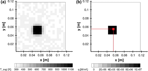
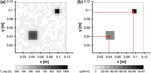
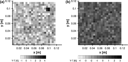
The synthetic measurements and the reference heat flux at time s are shown in Figure (a) and (b), respectively. Furthermore, Figure (b) also highlights one control volume, located inside the heated region at
mm, where the time evolutions of reference and estimated quantities are compared.
Figure 2. Case#1 (a) synthetic measurements and (b) exact heat flux at s.
4.1.1. Classical lumped analysis for Case#1
We first consider in this work the reduced model in the form of the classical lumped analysis, where the temperature gradients are neglected in the z direction (see Equation (Equation17a(17a)
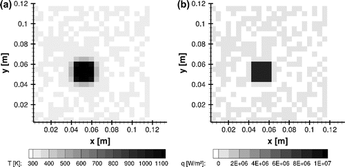
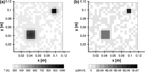
(17a) )). The contour plots of the estimated temperatures at
and of the applied heat flux at
, at
s, are presented by Figure (a) and (b), respectively. A comparison between Figures and reveals an excellent agreement between reference and estimated values.
Figure 3. Case#1 estimates at s using the classical lumped analysis: (a) temperature and (b) heat flux.
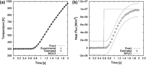
The comparison of the time variations for both estimated and exact temperature and heat flux values at mm are shown in Figure (a) and (b), respectively. The agreement between the reference and estimated temperatures is excellent. As for the heat flux estimation, it takes
s for the estimates to approach the imposed heat flux of
W m
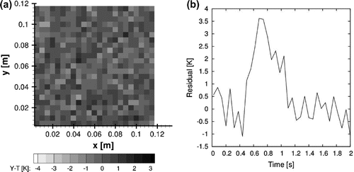
. However, the reference value of the heat flux is not exactly recovered (the 99% confidence interval of the estimated flux does not encompass the exact flux). In fact, the estimated flux decreases for times >1.2 s, instead of keeping the constant exact value. This behaviour is due to the modelling errors of the reduced model in comparison to the complete model. The temperature residuals are shown both as a contour plot (spatial distribution at
s) and as a line plot (time evolution at the selected control volume at
mm) in Figure (a) and (b), respectively. While the spatial distribution of the residuals in Figure (a) exhibit a random behaviour, a spike can be observed at
s in Figure (b), when the residuals are much larger than the standard deviation of the synthetic measurements, thus, demonstrating a correlated behaviour typical of models that do not appropriately represent the physics of the problem, such as the reduced model used in this example.[Citation4,Citation19]
Figure 4. Case#1 time evolution of temperature at z = 0 (a) and heat flux (b) at the selected control volume using the classical lumped analysis.
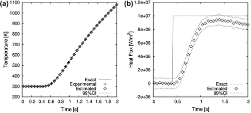
Figure 5. Case#1 analysis of the residuals from classical lumped analysis with heat flux W m
: (a) spatial distribution at
s and (b) time evolution at the selected control volume.
4.1.2. Improved lumped analysis for Case#1
The results for the improved lumped analysis (see Equation (Equation17b(17b)
(17b) )) are presented below. The contour plots of the estimated temperatures at
and the applied heat flux at
at
s are shown, in Figure (a) and (b), respectively. Similar to the classical lumped analysis, the results obtained here with the improved lumped analysis show an excellent agreement between reference and estimated values (see also Figure (a) and (b)).
Figure 6. Case#1 estimates at s using the improved lumped analysis: (a) temperature and (b) heat flux.
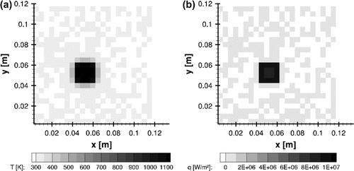
Table 2. Parameters of the heat flux used in the simulation of measurements for Case#2.
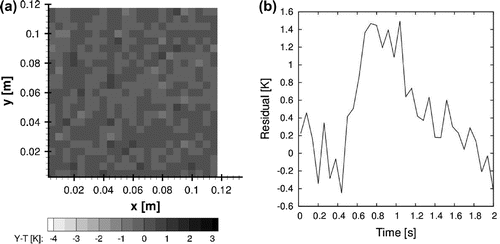
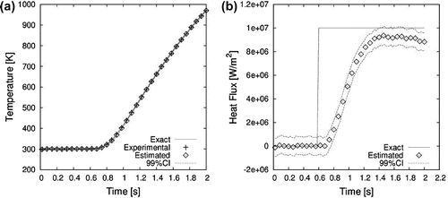
The comparisons of the time evolutions of exact and estimated temperatures and heat flux at the selected control volume ( mm) are presented by Figure (a) and (b), respectively. The agreement between estimated and exact temperatures is excellent, as depicted by Figure (a). It is shown in Figure (b) that the exact heat flux of this test case can be quite well recovered after a time lag of
1 s. Different from the case involving the classical lumped analysis (see Figure (b)), the estimated heat flux with the improved lumped analysis does not decrease and its magnitude is the same as that of the exact flux.
The temperature residuals over the plate at s and the transient variation of the residuals at
mm, are presented by Figure (a) and (b), respectively. Because of the model reduction for the solution of the inverse problem, Figure (b) shows correlated residuals. On the other hand, the residuals obtained with the improved lumped formulation (Figure (b)) are smaller than those obtained with the classical lumped formulation (Figure (b)). Such is the case because, in the improved lumped analysis, the temperature gradients are not completely neglected, but taken into account in an approximate form; thus, the modelling errors are much smaller.[Citation4]
4.2. Case#2 (one hot spot with heat flux W m and one hot spot with heat flux W m)
For this test case, the heat flux applied at was considered to follow Equation (Equation24
(24)
(24) ), with parameters given by Table .
(24)
(24)
Figure 7. Case#1 time evolution of temperature at (a) and heat flux (b) at the selected control volume using the improved lumped analysis.
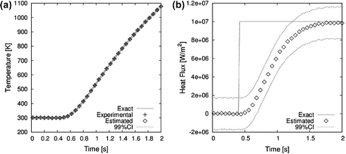
Figure 8. Case#1 analysis of the residuals from improved lumped analysis with unsteady heat flux applied at : (a) spatial distribution at
s and (b) time evolution at the selected control volume.
The synthetic measurements and the reference heat flux at time s are shown in Figure (a) and (b), respectively. Figure (b) also highlights two control volumes, located inside the heated regions at
mm and
mm, where the time evolutions of reference and estimated quantities are compared.
Figure 9. Case#2: (a) synthetic measurements and (b) exact heat flux at s.
4.2.1. Classical lumped analysis
The contour plots of the estimated temperatures at and of the applied heat flux at
, at
s, are presented by Figure (a) and (b), respectively. A comparison of Figures and reveals an excellent agreement between reference and estimated values.
Figure 10. Case#2 estimates at s using the classical lumped analysis: (a) temperatures and (b) heat flux.
The comparison of the time behaviour for both estimated and exact temperature and heat flux values at mm and
mm are shown by Figures and , respectively. The agreement between the reference and estimated temperatures is excellent for both spots. The heat flux applied at
mm is accurately identified with a delay of 0.6 s, while the estimated flux at
mm reaches its maximum value after 0.8 s. Such as for case#1, the exact value of the flux was not recovered when its magnitude was of
W m
, as shown by Figure (b). These results show more clearly the effects of the approximation errors, which become dominant with larger temperature gradients imposed by a larger heat flux. In fact, Figure (b) shows that the estimated flux is in very good agreement with the exact one for of
W m
.
Figure 11. Case#2 time evolution of temperature at (a) and heat flux (b) at the selected control volume at
mm using the classical lumped analysis.
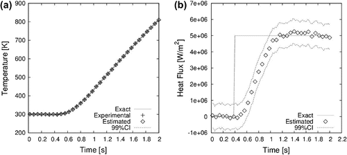
Figure 12. Case#2 time evolution of temperature at (a) and heat flux (b) at the selected control volume at
mm using the classical lumped analysis.
The time variations of the temperature residuals at mm and
mm are presented by Figure (a) and (b), respectively, while the contour plots of the residuals at
s and
s are presented by Figure (a) and (b), respectively. The time evolution of the residuals shows a correlation behaviour, which results from the use of the reduced model. Besides that, the residuals increase in magnitude near the instant that the heat flux are applied. It is shown in Figure (b) that the residuals exhibit a random spatial behaviour at the final time but, at
s, it is larger in the region where the heat flux of large magnitude is applied.
Figure 13. Case#2 time evolution of the residuals from classical lumped analysis: (a) mm and (b)
mm.
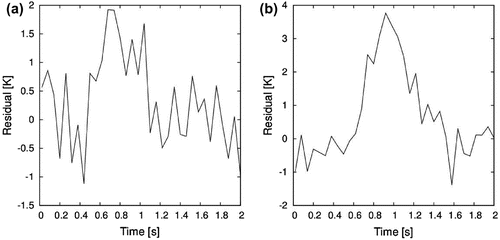
Figure 14. Case#2 spatial distribution of the residuals from classical lumped analysis: (a) s and (b)
s.
4.2.2. Improved lumped analysis in Case#2
The contour plots of the estimated temperatures at and the applied heat flux at
at
s are shown in Figure (a) and (b), respectively. Similar to the classical lumped analysis, the results obtained here with the improved lumped analysis show an excellent agreement between reference and estimated values (see also Figure (a) and (b)). The comparisons of the time evolutions of exact and estimated temperatures and heat flux at the selected control volumes (
mm and
mm) are presented by Figures and , respectively. The agreement between estimated and exact temperatures is excellent, as depicted by Figure (a). It is shown in Figure (b) that the exact heat flux at
mm is accurately identified after 1 second. The qualitative behaviour is similar to the one observed with the reduced model based on the classical lumped analysis. As for the heat flux at
mm, Figure (b) shows that for case#1, the heat flux of larger magnitude could be accurately recovered when the improved lumped formulation was used for the model reduction, since the modelling errors are smaller. It is presented in Figures and the time variations of the residuals at selected locations and the spatial distributions of the residuals at selected times, respectively. These figures show behaviours for the residuals similar to those observed with the classical lumped formulation, but the magnitude of the residuals are smaller due to the smaller modelling errors. The same peaks were observed around the respective times where the heating was imposed, but with smaller maximum values, around half the ones observed when using the classical lumped analysis (see also Figures and ).
Figure 15. Case#2 estimates at s using the improved lumped analysis: (a) temperatures and (b) heat flux.
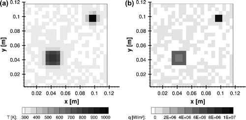
Figure 16. Case#2 time evolution of temperature at (a) and heat flux (b) at the selected control volume at
mm using the improved lumped analysis.
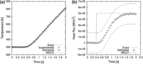
Figure 17. Case#2 time evolution of temperature at (a) and heat flux (b) at the selected control volume at
mm using the improved lumped analysis.
Despite the correlated residuals, the model reduction used in this work, either by the classical lumped analysis or by the improved lumped analysis, results in quite accurate estimates of the imposed heat flux, both in terms of its transient variation as well as of its spatial distribution. Note that the presented methodology, which also involves an approximation in the KF recursive equations, was capable of identifying heat flux of quite large magnitudes, imposed on small regions of the plate, and with a step variation. Although the correlated residuals resulting from the model reduction could be improved by using the Approximation Error Model approach,[Citation4,Citation7,Citation13,Citation19] such a technique was not applied in this paper in light of the excellent estimation of the applied unsteady heat flux that is obtained in real time, as demonstrated next, when we discuss the computational effort obtained. Of course, the reduced model used here may fail for other conditions of larger temperature gradients across the plate, but the Approximation Error Model [Citation4,Citation7,Citation13,Citation19] can then be applied in these cases, to account for the errors between the complete and the reduced models.
Figure 18. Case#2 time evolution of the residuals from improved lumped analysis: (a) mm and (b)
mm.
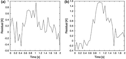
Figure 19. Case#2 spatial distribution of the residuals from classical lumped analysis: (a) s and (b)
s.

4.3. Computational effort
For the results presented in this work, all computations were performed on an Intel®CoreTM i7-3770 [email protected] GHz with 16 GB of RAM, running a 64-bit Linux operating system. With the exception of the SLICOT library used to solve the DARE equation, all computer codes were developed using FORTRAN90 language and compiled using the gfortran compiler. No libraries for parallelization were utilized.
The solution of the DARE is independent of the application of the SSKF; it depends only on the matrices of the evolution and observation models, but not on the sought heat flux and temperatures. Therefore, the DARE can be solved only once and offline, i.e. it is not solved sequentially, within the KF. The computation of the DARE solution took about five minutes of computational time.
After the solution of the DARE, the application of the SSKF to the cases examined herein took 0.9 s of computational time, for a simulated process with physical duration of 2.0 s. Therefore, the simulated experiments presented in this paper reveals that, for the application under analysis, the boundary heat flux can be estimated in real time, since the computational time was in general smaller than the actual duration of the physical problem. This is a significant improvement in comparison with other published works [Citation5–Citation7] where the computational times were of the order of several minutes and an online estimation of the heat flux would not be possible.
5. Conclusions
This paper dealt with the sequential estimation of a boundary heat flux applied on the surface of a plate, by taking transient temperature measurements over the opposite surface of the plate. Due to the large temperature gradients in the cases examined here, which involved heat flux of large magnitudes and applied over small regions of the surface, the formulation of the forward problem was given in terms of three-dimensional nonlinear heat conduction. For computational speedup, two reduced forward models were used; they were obtained from partial lumping across the plate thickness of the linearized version of the original complete model, thus, resulting in a two-dimensional linear problem. The sequential solution of the inverse problem was obtained with a steady-state version of the KF, in which the required matrices for its recursive equations were computed offline. Although not formally resulting in optimal solutions, such version of the KF is computationally much faster than the classical KF.
From the two reduced models examined in this paper, the one obtained with the improved lumped approach generally resulted in more accurate estimations than that obtained with the classical lumped approach, since the modelling errors were smaller. The two model reductions allowed for fast computations with the SSKF, which requires linear evolution and measurement models. The results obtained in this paper, with two different test cases, show that the magnitudes and locations of the concentrated heat flux can be accurately recovered with the present solution approach, based on reduced linear models and the SSKF, even for quite large uncertainties in the evolution model and in the measurements. Moreover, the computational time was in general smaller than the actual duration of the physical problem. Therefore, the boundary heat flux can be estimated in real time, which allows for possible control and/or counteract strategies for the sake of protecting the plate integrity.
Acknowledgements
The authors would like to thank the Brazilian agencies for the fostering of science.
Additional information
Funding
Notes
No potential conflict of interest was reported by the authors.
References
- Dennis BH, Dulikravich GS. Simultaneous determination of steady temperatures and heat fluxes on surfaces of three dimensional objects using FEM. In: IMECE. New York (NY): ASME; 2001.
- Dennis BH, Dulikravich GS. Simultaneous determination of temperatures, heat fluxes, deformations, and tractions on inaccessible boundaries. ASME J. Heat Transfer. 1999;121:537–545.
- Dennis BH, Dulikravich GS. Inverse determination of unsteady temperatures and heat fluxes on inaccessible boundaries. Inverse Ill-Posed Prob. 2012;20:791–803.
- Orlande H, Dulikravich G, Neumayer M, et al. Accelerated Bayesian inference for the estimation of spatially varying heat flux in a heat conduction problem. Numer. Heat Transfer; Part A. 2014;65:1–25.
- Pacheco CC, Orlande HRB, Colaço MJ, et al. Estimation of a spatial and time dependent high magnitude heat flux using the Kalman filter. In: 15th Brazilian Congress of Thermal Sciences and Engineering. Belém; 2014.
- Pacheco CC, Orlande HRB, Colaço MJ, et al. Identification of a position and time dependent heat flux using the Kalman filter and improved lumped analysis in heat conduction. In: 5th International Conference on Computational Methods. Cambridge, MA; 2014.
- Pacheco CC, Orlande HRB, Colaço MJ, et al. Estimation of a location-and-time dependent high magnitude heat flux in a heat conduction problem using the Kalman filter and the approximation error model. Numer. Heat Transfer, Part A. 2015;68:1198–1219.
- Afrin N, Feng ZC, Zhang Y, et al. Inverse estimation of front surface temperature of a locally heated plate with temperature-dependent conductivity via Kirchhoff transformation. Int. J. Therm. Sci. 2013;69:53–60.
- Feng ZC, Chen JK, Zhang Y, et al. Estimation of front surface temperature and heat flux of a locally heated plate from distributed sensor data on the back surface. Int. J. Heat Mass Transfer. 2011;54:3431–3439.
- Simon D. Optimal state estimation: Kalman, H∞, and nonlinear approaches. Hoboken, NJ: Wiley; 2006.
- Griggs JL. Private communications. SAIC; 2011.
- Cotta RM, Mikhailov MD. Heat conduction: lumped analysis, integral transforms, symbolic computation. New York, NY: Wiley Ed.; 1997.
- Kaipio JP, Somersalo E. Statistical and computational inverse problems. New York, NY: Springer Science+Business Media; 2004.
- Orlande HRB, Colaço MJ, Dulikravich GS, et al. State estimation problems in heat transfer. Int. J. Uncertainty Quantification. 2012;2:239–258.
- Kalman RE. A new approach to linear filtering and prediction problems. Trans. ASME -- J. Basic Eng. 1960;82:35–45.
- Grewal MS, Andrews AP. Kalman filtering: theory and practice using MATLAB. New Jersey, NJ: Wiley; 2008.
- Chen Z. Bayesian filtering: from Kalman filters to particle filters, and beyond. Statistics. 2003;182:1–69.
- Benner P, Mehrmann V, Sima V, et al. SLICOT -- a subroutine library in systems and control theory. In: Datta B, editor. Applied and computational control, signals, and circuits se - 10. Birkhäuser Boston; 1999. p. 499–539. Available from: http://dx.doi.org/10.1007/978-1-4612-0571-5\_10
- Huttunen J, Kaipio JP. Approximation and modelling errors in nonstationary inverse problems [dissertation]. Kuopio, Finland: Kuopio University Library; 2008.