 ?Mathematical formulae have been encoded as MathML and are displayed in this HTML version using MathJax in order to improve their display. Uncheck the box to turn MathJax off. This feature requires Javascript. Click on a formula to zoom.
Abstract
This article presents a new concept of using the one-dimensional piezo-electric patch on beam model for structural identification (SI). A hybrid element constituted of one-dimensional beam element and a PZT sensor is used with reduced material properties. Accuracy of this element is first verified against a corresponding 3D finite element model. Then SI is carried out as an inverse problem whereby parameters are identified by minimizing the deviation between the predicted and measured voltage response of the patch, when subjected to impulse excitation. A non-classical optimization algorithm Particle Swarm Optimization is used to minimize this objective function. Identified parameters involve stiffness, damping as well as the depth and location of crack in a beam. The validity of the proposed approach is proved by numerical studies on a beam, nine member frame and crack depth and location identification using various patch lengths. The signals are polluted with 5% Gaussian noise to simulate experimental noise. The results show there is a significant improvement in identification accuracy compared to other methods. The proposed method is also successfully verified experimentally.
1. Introduction
Structural identification (SI) is a class of inverse problem which deals with how to estimate structural parameters such as stiffness and damping from the measurement of input excitation and the corresponding output response. SI takes part important role in model updating and structural health monitoring. SI algorithms are generally categorized into the frequency, modal and time domain, parametric and nonparametric models, and deterministic and stochastic approaches, and classical and non-classical methods.[Citation1,Citation2]
Chakraborthy and Mukhopadhyay [Citation3] estimated simultaneously elastic parameters and cross-sectional dimensions of a stiffened plate from experimental modal data and Finite Element (FE) predictions, using model updating technique. The method used mode shape and frequency error function between simulated ‘experimental’ and FE model values were minimized by Levenberg Marquardt algorithm. Kianian et al. [Citation4] investigated damage detection of offshore jacket platforms exploiting a method which applies frequency response function data-set in some frequency points and also the proper methodology applied to the selection of frequency points to improve the damage detection efficiency. Yang and Wang [Citation5] introduced a new damage detection method based on the new conception of natural frequency vector and natural frequency vector assurance criterion and verified by both simulative and experimental examples. Wang et al. [Citation6] suggested a two-stage identification algorithm utilizing the changes in natural frequencies and static displacements, for identifying the structural damages. Liu et al. [Citation7] identified the presence of structural damage using multi-objective optimization, keeping variations in natural frequency and mode shapes as individual objective functions. However, all these methods based on frequency domain may not be suitable for the large complex system which requires high frequency resolution, local damage assessment or non-linear parameter determination.[Citation2] Moreover, damping properties of structures cannot be estimated and also need some transformation of dynamic response data which requires more computational effort.[Citation8]
In this respect, time domain algorithm SI schemes are a better alternative and it has an advantage that structural response can be directly used without any transformation.[Citation9] Time domain algorithms are generally classified as classical (least square (LS), Extended Kalman filter and maximum likelihood method etc) or non-classical methods (neural network and evolutionary algorithm).[Citation10] Goa and Lu [Citation11] investigated a method for the time-domain analysis of noise-contaminated vibration signals for global structural damage diagnosis. The proposed method is based on conjunction with time-domain analysis approach based on Auto-Regressive with exogenous input (ARX) and Kalman filter technique. Kang et al. [Citation8] presented a time domain algorithm to estimate the stiffness and damping parameters of the structure using measured acceleration. The proposed SI algorithm estimates structural parameters through the minimization of an error function defined by the time integral of the least-squared error between the measured and the calculated accelerations. Koh et al. [Citation12] applied substructural and progressive identification method in time domain using interface measurements. It will reduce the number of unknown structural parameters to be identified, reducing the computational effort. In general the classical methods work well, but they do face problems in getting stuck in local optima, sensitivity to noise, and requirement to give an initial value by the user. These are avoided when using non-classical optimization methods.[Citation12]
A non-classical method is usually based on heuristic concepts such as Genetic Algorithm (GA) based on Evolutionary principle or Particle Swarm Optimization (PSO) on behavioural principle. Varghese and Shankar [Citation13] used PSO for SI based on the combined objective function of power flow balance and acceleration matching. It is based on weighted aggregation approach and identified the crack location and depth with better accuracy than the conventional acceleration matching methods. Nandakumar and Shankar [Citation9] proposed damped transfer matrix and state vectors for structural parameter estimation using PSO. Koh et al. [Citation10] proposed hybrid of GA and compatible local search operator for the identification of structural system with 52 unknown parameters. Zhenghao Ding et al [Citation14]identified multiple cracks using improved artificial bee colony algorithm (I-ABC) based on objective function which consists of limited number of measured natural frequencies. Hu et al. [Citation15] identified cracks using homotopy continuation algorithm based on using several measured acceleration responses. Lia et al. [Citation16] used a derivative of eigen-parameters-based model updating approach for the damage identification of multiple cracks.
Cracks in a structural member reduce the local stiffness which affects vibrational response. Gounaris et al. [Citation17] identified the crack depth and location of a Timoshenko beam FE of six degrees of freedom per node, using a coupled response measurement. However, it is suitable for only single edge non-propagating crack present in the beam and it requires many nomograms for enhancing the accuracy and utility of the identification procedure. Krawczuk et al. [Citation18] developed single edge cracked beam FE which is based on Elasto-plastic fracture mechanics theory. The crack is transverse open edge and is found that crack tip plasticity increases the predictive capability of the model and also inertia matrices are same as for non-cracked element. Viola et al. [Citation19] formulated shape functions of a cracked Timenshenko beam element and used them for identification of the magnitude and location of the crack based on experimentally measured frequencies and mode shapes. Viola et al. [Citation20] investigated the effect of cracks in the stiffness matrix, neglecting the crack closure effect by assuming an open crack.
Sumant and Maiti [Citation21] predicted crack location and depth using a experimentally measured voltage drop between healthy and damaged beam with pair of PZT patches subjected to static loading. Here, the identification is only significant when the distance between a crack and a patch along the edge is approximately less than the depth of the beam. Two stage identification is proposed by Fukunaga et al. [Citation22] using a limited number of PZT sensor in time and frequency domain. It identified crack depths up to 10%, but it strongly depends on reliable modal data of undamaged structure.
The high reliability, sensitivity and electromechanical coupling property of PZT has gained significant attention for potential application as sensors for monitoring and as actuators for controlling the response of structures. Shen [Citation23] proposed a one-dimensional mathematical model for determining the mechanical responses of beams with PZT as actuator and as a sensor. Bendary and Raid [Citation24] formulated one-dimensional integrated beam element using hermit cubic and Lagrangian interpolation function and carried out static and dynamic analysis. Zemcik and Sadilek [Citation25] developed one-dimensional hybrid PZT element based on the Euler Bernoulli beam using bilinear Lagrangian interpolation polynomial for electric potential and carried out modal analysis. Later, the same element is used for frequency response analysis and the result is experimentally verified by Sadilek and Zemcik [Citation26]. Sulbhewar and Raveendranath [Citation27] formulated one-dimensional Euler Bernoulli beam with PZT structure using coupled field polynomial which is independent of material configuration of the piezoelectric beam cross section.
In most of the literature presented accelerometer signal is used as inverse quantity for SI. However, compared to accelerometer, PZT patches have the advantages of low cost, light weight, wide dynamic range. The most notable feature of PZT patches is their miniaturized appearance and ability to be implanted in civil structure for in situ health monitoring of structure. Moreover, because of their light weight the PZT patches are not likely to alter the dynamic properties and also output voltage is less contaminated with noise signal. To the best of the author’s knowledge, this is the first attempt to use voltage output from one-dimensional model PZT patch as an inverse problem for the SI with crack. The theory is validated with numerical and experimental examples in the section given below.
2. Constitutive equations of PZT
Piezo Electric Materials are used to transform the mechanical displacement into an electrical field (voltage potential) in which case the piezoelectric material acts as a sensor(direct effect), and its converse effect acts as an actuator. The constitutive equations for the transversely isotropic piezo electric medium which define the interaction between the stress (), strain (
), electric displacement (D) and electric field (E) in the form [Citation28]
(1)
(1)
(2)
(2)
where ,
and
and
are elastic, dielectric and piezo electric coupling coefficient, respectively. The transversely poled piezoelectric material is bonded/embedded in host structure. The complete coupled three-dimensional constitutive equation of a piezo electric material with principal material axis (x, y and z) can be written as follows [Citation27]
(3)
(3)
where and
are shear stress and shear strain, respectively
3. One dimensional beam geometry
The simple three-dimensional beam with axis is shown in Figure . The Euler–Bernoulli beam theory is applied for one-dimensional beam with piezo electric patch, which neglect the shear effect. The model is assumed to be plane stress and width in the y direction has zero stress. Therefore, it is possible to set while
;
[Citation27]. The polarization axis z is aligned with the thickness direction of the beam, thus only
is taken and thus for electric field
. Applying these condition in Equation (Equation3
(3)
(3) ) and it is reduced in the form
(4)
(4)
where and
;
and
;
and
.[Citation29] Here,
,
and
are reduced elastic, dielectric and piezo electric coupling coefficient, respectively, and these calculated values are shown in Table . This reduced property is used for further numerical study of one-dimensional beam with PZT patch in MATLAB®.
Table 1. Material properties of the beam.
4. Analytical and FEM formulation
One-dimensional beam formulation has been presented in Refs. [Citation26,Citation27], but not used for time domain dynamic response with damping and inverse problem. The FE formulation of the structure is briefly explained here. The beam element is based on the Euler–Bernoulli theory and element has two nodes. The two independent polynomials are used for interpolation of mechanical and electrical field variable. First hermit cubic polynomial is used for the interpolation of mechanical quantities of vertical displacement (w) and rotation () as shown in Figure . Let the vertical displacement (w) is approximated across the length as
(5)
(5)
where is the shape interpolation function, and structural nodal degree of freedom per element is arranged as
(6)
(6)
Thus Equation (Equation5(5)
(5) ) can be written as
(7)
(7)
where(8)
(8)
The axial displacement can be written as(9)
(9)
Thus bending strain is(10)
(10)
where is the strain–displacement matrix consisting of derivatives of shape functions.
The electric potential is considered as a function of the thickness and the length of the beam. Hence, let langrangian bilinear function is estimated for the interpolation as
(11)
(11)
As shown in Figure , and
are lower and upper electrical potential of PZT surface. The electrical nodal degree of freedom per element can be ordered as
(12)
(12)
Thus Equation (Equation11(11)
(11) ) can be written as
(13)
(13)
where(14)
(14)
The electric field E(x, z) and electric potential can be related as follows
(15)
(15)
Thus it can be written as follows(16)
(16)
where is the Electrical field-potential matrix consisting of derivatives of shape functions.
Here, homogeneous electrical boundary condition is imposed on the bottom surface of PZT patch to eliminate rigid body modes i.e. Lower surface is grounded with V, while the upper surface was left open.
5. Evaluation of elemental matrices
The dynamic potential energy density G for the piezo electric medium can be written as [Citation31](17)
(17)
It includes contribution from mechanical and electrostatic energy and kinetic energy density is(18)
(18)
Then apply variational principle to potential, kinetic energy and external forces (mechanical and electrical loading). It must be satisfied for any arbitrary variation of the displacements and electrical potentials and thus equation of motion of elemental matrices can be represented as [Citation32](19)
(19)
The Equation (Equation19(19)
(19) ) is the elemental equilibrium in the discretized form, where
is the mass matrix,
is the stiffness matrix corresponding to the mechanical degree of freedom,
is the stiffness matrix due to electromechanical coupling,
is the stiffness matrix due to the electrical degrees of freedom alone,
is the mechanical load vector and
is the electrical charge load vector. The size of each element matrices are
and are given by
(20)
(20)
In general, all structures are lightly damped. Thus, adding an artificial linear viscous damping to Equation (Equation19(19)
(19) ) [Citation32]
(21)
(21)
where the damping matrix is defined as a proportional damping i.e.
(22)
(22)
where a and b are Rayleigh’s damping coefficients.
The matrices of equations are then assembled to obtain the global dynamic system equation. In order to solve this, the global matrix Equation (Equation21(21)
(21) ) can be expanded and written as:
(23)
(23)
The second part of Equation (Equation23(23)
(23) ) is simplified as
(24)
(24)
The above equation is substituted in the first part of the (Equation23(23)
(23) ) and is written as
(25)
(25)
where(26)
(26)
For the sensor problem, displacement histories are obtained by solving Equation (Equation25(25)
(25) ) and substituted in (Equation24
(24)
(24) ), and voltage vector across the sensor patch is obtained. In order to perform modal analysis, the above system is statically condensed and equation is modified to
(27)
(27)
and the problem is reduced to the eigen value of the matrix(28)
(28)
6. Numerical validation of one dimensional FE model
A computer code for the above-described hybrid beam element in MATLAB® environment has been developed to study the dynamic analysis of PZT sensor bonded to the top surface of cantilever beam as shown in Figure . The dimension of the rectangular beam is taken from Sandesh and Shankar [Citation30] and PZT sensor dimensions are (). The material properties of host structure (Aluminium) and PZT sensor (reduced properties) are used as shown in Table . As no commercial one-dimensional PZT element is available, the present formulation is validated using ANSYS® 3D simulation.
For Ansys® 3D simulation a mesh of SOLID 186 element is used for the host structure and a mesh of SOLID 226 element is used for sensor(PZT 5H) patch.
Modal Analysis is carried out first for the given model and first three natural frequencies are tabulated in Table . As shown from table, natural frequency from present formulation is in good agreement with ANSYS® 3D simulation. The convergence test has been done for Ansys model using smaller elements.
Table 2. Natural frequency of cantilver beam structure.
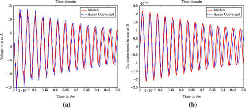
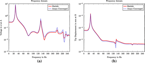
In time domain analysis, numerically simulated response histories of all DOFs of the model are calculated in terms of displacement, velocity, acceleration and voltage using Newmark-Beta method. An impulsive force of 2 N in time period of 0.01 s in time step of 0.001 is applied in the free end of a cantilever beam. The effect of the damping was accounted by Rayleigh’s damping with modal damping ratio of 1% at its first two modes. The tip deflection time histories at point B in vertical direction and maximum voltage potential (near the clamped end) time history at PZT patch A are plotted in Figure . As seen from the plot, the present MATLAB® code gives precise predictions as given by the ANSYS® simulation. Comparable validation is also done in the frequency domain and which are shown in Figure . From this plot, two well-defined peaks are identified as first two modal frequencies. The result compares well with ANSYS® 3D simulation.
7. PSO algorithm
A heuristic optimization technique referred to as PSO is used here which mimics the social behaviour of swarms. It was first proposed by James and Ebehart [Citation33]. It imitates the social behaviour of a swarm of birds. Each bird will tend to follow the general swarm direction in search of the target (food), but it has a component of its own intelligence and memory (i.e. local search) which influences its action. Each bird is visualized as a ‘particle’ which approaches the target (i.e. the global optima) with a ‘velocity’. The number of particles (i.e. population) and their initial random positions are specified. As the particles progress to the global optima through many generations, their current position is updated using two parameters which represent the historically best co-ordinate of all the particles in the population and
the historically best co-ordinate of the ith particle. The equations giving the velocity v and position x for the ith particle in the
generation are given by,
(29)
(29)
(30)
(30)
where i is the particle index, k the discrete time index, v the velocity of the ith particle, x the position of the ith particle/present solution. Here and
represent two random numbers between 0 and 1,
is an inertia term uniformly decreasing from 0.9 to 0.4 with generations and
and
are two acceleration constants set to two.[Citation34] Several studies have pointed out the superiority of PSO algorithm over the more conventional heuristic algorithms such as GA for inverse problem applications.[Citation35,Citation36]
8. Structural parameter identification using PZT patch
The time domain-based approach is used and voltage history is used as the main response quantity in the identification procedure. A few experimentally measured voltage potential responses are measured from PZT patches. The estimated voltage potential
is obtained from mathematical model using Equation (Equation24
(24)
(24) ). For exact identification,
has to match with experimentally measured responses
. In this method, experimental responses are simulated from a known numerical model and polluted with Gaussian noise of zero mean and a certain standard deviation for practicality. Using PSO algorithm the following fitness (objective) function is minimized, which is the sum of squares of deviations between the measured and estimated voltage.
(31)
(31)
The superscripts m and e denote measured and estimated responses for fitness evaluation, M is the number of measurement sensors used and L is the number of time steps. Ideally, it must be minimized to zero, but usually it approaches a value close to zero.
9. Numerical results and discussion
In order to validate the proposed method, various numerical simulations are carried out. The purpose of these numerical simulations is to study the effect of patch size on the accuracy of identification. Three cases studied here are (a) stiffness identification of a beam (b) a more complex structure i.e. sub structure of nine member frame and (c) crack identification (magnitude and location) in a beam structure. Experimental measured responses are numerically simulated from a fully defined model in MATLAB® using Newmark’s constant acceleration scheme. The structure is excited by a impulse force and responses are measured at PZT patches. The mass of the structure is assumed to be known a priori and the stiffness parameters are the unknowns to be identified for the first two cases. These are estimated using the inverse formulation with a single objective approach. In order to simulate the effect of noise in experiments, Gaussian random noise level of 5%(standard deviation) and zero mean is added to all the measured signals. The noise is added with simulated responses in such a way that,(32)
(32)
where g is the standard Gaussian variable, is the Root Mean Square (RMS) value of the numerically simulated signal and NL is Noise level.
In this numerical study, three different PZT patch lengths are investigated and are PZT:5, PZT:10 and PZT:20%. They, respectively, represent the length of the patch expressed as percentage of beam length. The width of PZT is same as host structure and a constant thickness of 1 mm is used for this study.
9.1. Fixed-fixed beam structure
The proposed method is first applied to fixed–fixed beam as shown in Figure . Model geometry and properties of host structure (Aluminium) are taken from [Citation30]. In this study, two PZT patches are bonded on either side of the structure and the beam is divided into five Euler–Bernoulli beam elements. The Flexural rigidity (EI) of each element is 38.48 . The first and second natural frequency of modes of vibration are 148.46 and 415.06 Hz respectively. Rayleigh damping with the modal damping ratio of 3% is used for the first two modes of vibration. The beam is excited by providing an impulse force of 2 N at node 4 over a time of 0.01 s in the time step of 0.001.
The unknown parameters such as stiffness and damping are obtained by PSO in the range of of actual value. In this PSO parameters are set to 100 particles (swarm size) and 200 generations. First, in this study we compare the identification of structural parameters by voltage matching with different lengths of PZT. The identified results are shown in Tables and , respectively. From tables, it can be seen that for noise free case Mean Absolute Error (MAE) of PZT-10% i.e.
PZT) is 0.089% and whereas PZT-5% i.e.
PZT) is 0.136%. The percentage increase of error compared with these two cases is only 34.5%. Similarly for 5% noise case, it is 0.111 and 0.167%, respectively, and percentage change of error of these two cases is 33% only. The percentage of error in identifying damping constants
and
of PZT-10% are 0.032% and 0.002% for noise free case and is 0.109 and 0.242% for 5% noise, respectively. Similarly for PZT-5% the results are 0.044 and0.442% for no noise and 0.109 and 0.563 for 5% noisy case, respectively.
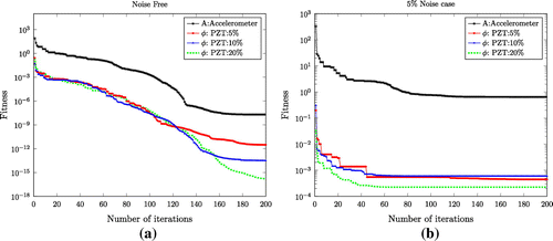
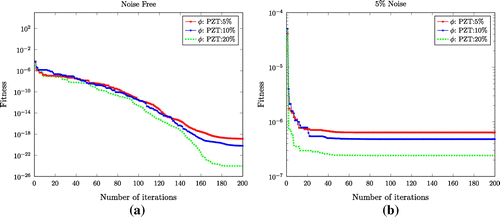
The objective function convergence study in identifying stiffness and damping coefficient for beam structure without and 5% noise contamination is presented in Figure . The Figure shows convergence of voltage matching () using different lengths of PZT sensor and acceleration matching (A) with accelerometer sensor (placed at node no:3). The method of acceleration matching is discussed in studies on Ref. [Citation10,Citation12,Citation13]. It is clear that as length of PZT increases, convergence is faster and thus identification error can be reduced. In Figure (a) and (b) shown, objective function of PZT:20% has minimized better than PZT:5 and PZT:10% and is most accurate in identification. However, it is not required to use such large patch length. PZT:5% error in identification is only 0.167% which is sufficient for practical use. As compared with pure acceleration matching, proposed method even with PZT:5% shows better convergence and thus identifies the parameters with better accuracy.
A numerical study is carried out using 20 elements for the same configuration. The MAE of structural parameter identification using 20 elements with PZT:5% is increased to 5.35 and 8.29%, respectively, for noise free and noisy signals. The reason could be the difficulty in convergence of the optimization algorithm because of the number of unknown variables (element stiffness) which is now increased with more elements. Thus it appears that for a uniform beam, five elements are sufficient for SI.
9.1.1. Comparison of results with other time domain methods
The same problem is compared with acceleration matching using the accelerometer sensor without PZT patches. The results of structural parameter identification are shown in Table . The Mean Absolute Error for identifying stiffness for noise free and 5% noise are 0.343 and 0.841%, respectively, for acceleration matching method. The same problem of the cantilever was solved by sub structuring [Citation30] using LS technique with accelerometer. There, MAE of identified stiffness parameters was 4.5% at 3% noise level and damping parameters are very high of 13.72 and 21.24%, respectively, and average computational time was 300 s but identification error by voltage matching with PZT is much lower than the above methods and here, mean computational time is only 60 s. This shows that using PZT as SI shows improved results when compared with other time domain methods.
Table 3. Identified structural parameters for only voltage matching: PZT:10%.
Table 4. Identified structural parameters for only voltage matching:PZT:5%.
Table 5. Identified structural parameters for only acceleration matching.
9.2. Sub-structure of a frame structure
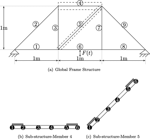
In this example, a steel frame structure consisting of nine members is fixed at two supports as shown in Figure as per Nandakumar and Shankar [Citation9]. Each member has flexural rigidity (EI) of 43.2 N.m and cross section of
mm. The fundamental natural frequency of the system is 12 Hz. Here, two members of structure as shown in Figure (a) and (b) were identified by the different PZT patch length as attempted in the previous example. Each frame is divided into five one-dimensional FEs. The structure is excited by an impulse response of 10 N at the midpoint of the member 6. Rayleigh damping with the modal damping ratio of 5% is used. The identified results of frame No:4 and frame No:5 using PZT:10% i.e.
PZT) and PZT:5% i.e.
PZT) is shown in Tables and , respectively. The MAE of member No:4, member No:5 without noise using PZT:10 and PZT:5% are 0.043, 0.053 and 0.109, 0.129%, respectively. The percentage increase of identified error compared with these two PZT patch lengths is 23.25 and 18.34%, respectively, for frame No:4 and frame No:5. Similarly for 5% noise case, these are 0.378, 0.436 (frame No:4) and 0.765, 0.959% (frame No:5), respectively, for PZT:10 and PZT:5%. The percentage increase of error compared with these two cases is 15.34 and 25.35%, respectively. The maximum percentage error of damping constant with 5% noise of frame No:5 are 4.23 and 5.56%, respectively, for patch length PZT:10 and PZT:5%. The frame No:4, it is 0.473 and 0.589 respectively, for PZT:10 and PZT:5%.
Convergence of fitness(objective) functions of different PZT length for the SI of frame N:4 (Noise free and 5% Noise) are presented in Figure . From the plot, it can be seen that PZT:20% has been minimized very well. However, it is not necessary to use in practice.
9.2.1. Comparison of results with other time domain methods
It may be noted that Nandakumar and Shankar [Citation9] have solved the same problem using transfer matrix in time domain method and identified the stiffness parameters with MAE of 0.47 and 1.01% in measurement with 3% noise at all measured response. Also damping constant was identified with maximum percentage error of 7.14% at the same noise level and mean computational time was 50 s There, the error is slightly more than the proposed approach and also implementation of current PZT method is much simpler than that of combined accelerometer and strain gauge for transfer matrices. The parameters of the same frame were identified by using the complete structural identification algorithm proposed by Koh et al [Citation12] with same input conditions and by same PSO parameters. The mean absolute error was 7.66% with complete measurement at all nodes without noise and required a computational time of 58 min for convergence. It is also compared with Yun and Babng [Citation37] using artificial neural network in frequency domain for structural identification of a very similar frame structure. The substructure of frame was identified with 5% noise with an average error of 8% and also it requires more computational time for training the data. It is shown that structural identification with PZT gives improved results and here, mean computational time is only 90 s.
10. Crack location and depth identification of a structure
The FE formulation of cracked model is taken from Viola et al. [Citation18,Citation19] and briefly presented here. However, it was not used for inverse problem, or combined with One-Dimensional PZT patch. The cracked beam element and corresponding FE model are shown in Figures and , respectively. Let be the length of the element,
be the location of the crack from its left end node, a be the crack depth measured from the top of the crack section. The cross-sectional dimensions of the beam are
.
Table 6. Percentage of error in identified parameters of frame structure: PZT:10%.
Table 7. Percentage of error in identified parameters of frame structure: PZT:5%.
It is derived based on elasto-plastic fracture mechanics and is as Euler–Bernoulli beam element having three segments.[Citation18] They are two intact segments and crack with negligible length and mass. The element has two nodes and with two degrees of freedom (transverse displacement and rotation) in each node. Since it is discontinued at the crack plane, two different polynomials are used for the interpolation of the field variable as follows [Citation18](33)
(33)
where to
are the constants, subscript 1 and 2 represents left and right side segment of the element, respectively. The four boundary conditions, at the cracked section where the elastic hinge is located are as follows:
(34)
(34)
where is the flexibility coefficient at the crack location, EI is the flexural stiffness and c be the torsional flexibility of the crack,
and
are the displacement and rotation at the nodes 1 and 2, respectively. The flexibility coefficient at the crack location can be also expressed as given in [Citation19]
(35)
(35)
where is a correction function which takes into account the body and crack geometry and depends on the dimensionless crack ratio
which can be represented in as follows [Citation19]
(36)
(36)
Using Equation (Equation34(34)
(34) ) and nodal values, the reduced shape function matrix [N(x)] of size 4
4 relates the nodal DOF with the field variables as follows [Citation18]:
(37)
(37)
The displacement in the cracked beam element can be written in terms of shape function from Equation (Equation7(7)
(7) ),
(38)
(38)
From FE procedure, the stiffness and mass matrices of the cracked element can be obtained as follows(39)
(39)
(40)
(40)
where and
are the respective rows of shape function matrix N(x). The value of
is zero, structure is considered as an intact element. The crack in the beam element has more dependence on change of stiffness, but it does not affect mass distribution appreciably.
10.1. Crack identification (depth and location) using PZT Patch
In this case, damage detection by the proposed method of voltage matching is applied to determine the magnitude (Depth) and location simultaneously for a single crack in the beam structure. The same cracked steel beam was studied in Ref. [Citation13,Citation19] is 520 mm long, 50 mm width and 8 mm thickness with Young’s modulus (E) 206 GPa and density of 7850 kg/m.
The fixed–fixed beam is divided into five Euler FEs with an open edge crack and is at a distance of 275.6 mm from the left fixed end as shown in Figure . The absolute normalized crack location measured from the left end of the beam is . In the FE model of the fixed–fixed beam, the crack is located in element 3. In this study, four different cases of normalized crack depth (
) are considered viz; 0.03, 0.05,0.1 and 0.5, respectively. The normalized crack location is measured from the left node of the element 3 is
.
In this study, as the first case two PZT patches with size PZT:5% i.e. PZT) is bonded on either side of the structure as shown in Figure . The first and second natural frequency of the modes of vibration are 156.18 and 436.08 Hz, respectively. Rayleigh damping with the modal damping ratio of 3% is used for the first two modes of vibration. First, the displacement, velocity and acceleration time history data are calculated for each nodal point using Newmark’s method with constant time step of 0.002 s in 0.01 s using the impulse force of 5 N in the vertical (upward) direction at node 4. Using the displacement response history, voltage responses are measured through two PZT patches. The numerically calculated voltages are polluted by artificially adding Gaussian white noise with zero mean and standard deviation of 5% to simulate experimental errors.
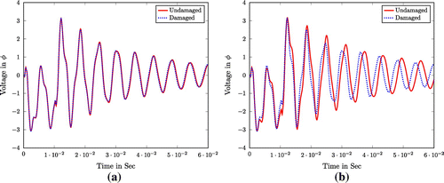
Here, Voltage difference between healthy and damaged states of structure for a small crack depth and
is observed to be very small. The Figure shows the undamaged and damaged responses available at the measurement PZT patch sensor A for normalized crack depths
and
cases, respectively. The shift in damaged response for a large crack is greater than a smaller crack.
It is assumed that the mass and flexural rigidity (EI) are known. Crack magnitude and location are set as the unknown variables for each element and thus there are 10 unknown variables in this problem. Thus the optimization variables to be identified are normalized crack depth and location
in five elements. The experimentally measured voltage response of PZT patches is required for the fitness evaluation. The mean square error (MSE) between measured and predicted voltage response at PZT patches are minimized by PSO. The lower and upper bound for PSO optimization to identify crack magnitude are set at zero and one. Similarly, the lower and upper bound to identify normalized crack location are set as zero and
, respectively. In this PSO parameters are to 100 particles( swarm size) and 500 generations as per previous literature.
The identified crack parameters using voltage matching with PZT:5% patches in various normalized crack depths of 0.03, 0.05, 0.1 and 0.5 with constant normalized absolute crack location () 0.53 as shown in Table . The MAE in normalized crack depth is 1.4875 and 4.8%, respectively, for noise free and 5% noise case. Similarly for the normalized absolute crack location, it is 0.1575 and 1.6325%, respectively. It can be seen that identified parameters in noisy environment show more error as compared to noise free case.
Table 8. Identified values of normalized damage magnitude and location using PZT:5%.
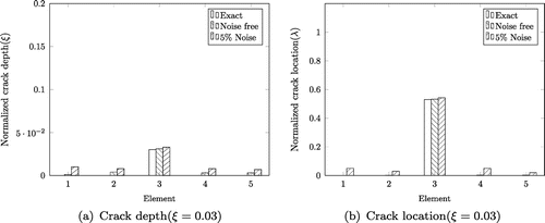
Figure (a) and (b) depict the element wise detection of crack depth and location for the case of . From the plot, it can be seen that all elements have very small magnitudes of normalized crack depth and location except the third element which is the correct cracked element. It is seen from Table that absolute error in noise is 3.33 and 0.377% for crack depth and location. But in the noisy case, it is 9 and 2.2%, respectively.
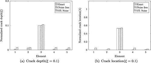
The Figure (a) and (b) shows the element wise details of normalized damage magnitude and location of crack of with same crack location. In the noise free case errors are very small such as 0.4 and 0.094%, respectively, for crack magnitude and location. For Noisy case, it is in the range of 4 and
%, respectively.
Next, the improvement of crack (depth and location) identification of smallest depth i.e. at the same location using PZT:10% i.e.
PZT) is identified. The identified results are shown in Table . Here the absolute error in noise free case is 2.67 and 0.32% for crack depth and location, respectively. The percentage decrease of error compared to PZT:5% is 19.8% and 15.11%, respectively. But for the noisy case, respective absolute errors are 6 and 2.075% and percentage decrease of error 33.33% and 5.68%, respectively.
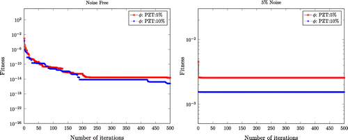
Figure (a) and (b) shows the convergence of fitness (objective) functions PZT:5 and PZT:10% for (noise-free and noisy case), respectively. The better minimization of PZT:10% when compared with PZT:5% is seen from the plot. Hence, the error of both magnitude and location is reduced.
10.1.1. Comparison with other damage detection methods
The results of Viola et al. [Citation19] are compared with results obtained from the proposed method. In Ref. [Citation19], a single crack with depth and absolute crack location
was identified using a frequency domain method from experimentally obtained measurements of unspecified noise content. The identified structural parameters are 0.486 and 0.756 and the percentage of the absolute error is 2.8 and 0.53%, respectively, for crack depth and location. The very same problem was also solved by Varghese and Shankar [Citation13] using the combined method of power flow and acceleration matching using substructure. The percentage of error in identifying crack depth and location was 0.92 and 0.5%, respectively, without noise and 1.72 and 2.8%, respectively, with 5% Noise. There, mean computational time was about 3000 s whereas with the proposed method it is 140 s Sumant and Maiti [Citation21] predicted the magnitude and location of
crack with errors of 9.33 and 4.95%, respectively, using static response of pair of PZT patch. But, in that case distance between sensor patch and crack should be less than crack depth (sensor is very near to crack) and also require undamaged structure details. The proposed method using voltage matching by PZT:5% identified the normalized crack depth (
) and location (
) was 0.02 and 0.019%, respectively, for noise free case and 0.2 and 0.94%, respectively, for noisy condition. And
, it was 9 and 2.2%, respectively, for depth and location in noisy condition. The results show that PZT-based damage identification using voltage is a promising method for crack depth and location identification.
Table 9. Identified values of normalized damage magnitude and location using PZT:10%.
The fixed–fixed beam described in the previous case is studied with two cracks and assumed that the cracks in different elements do not interact with each other. The cracks are assumed to be located at 143 and 221 mm from left end of beam, respectively. The normalized crack depth are 0.05 and 0 .5 and the corresponding normalized locations() from left end of fixed beam are 0.275, 0.425, respectively, for two cracks. Here, the crack lies in the second, third element and normalized crack location
from left end of the corresponding element are 0.75 and 0.25. The crack depth and location are identified accurately as listed in Table . The accuracy of identification is as good as single crack identification.
11. Experimental work:fixed–fixed beam with PZT Structure
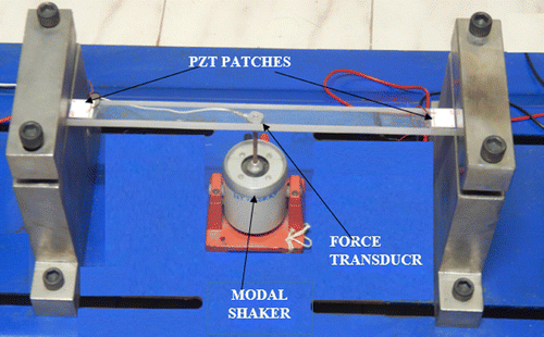
In this preliminary work, a brief experiment is carried out to identify stiffness and damping parameters of a fixed–fixed beam. A fixed–fixed beam made of acrylic material with dimensions mm is used for the experimental study. Here two PZT patch of dimensions
mm each are bonded at the fixed ends of the structure as shown in Figure . The modulus of Elasticity (E) was estimated to be 3.9 GPa from a simple bending test and the density was measured to be 1190 kg/m
. The actual flexural rigidity (EI) of the beam is 14.04 N.m
. The damping ratio(
) was calculated from a simple free vibration decay test using logarithmic decrement and estimated as 8%. The natural frequencies for the first two modes of the structure are calculated from the frequency domain as 110 and 306 Hz. Assuming Rayleigh’s proportional damping model, exact values of damping constants
and
are calculated as 81.64 and 6.12
, respectively, for two modes. The beam was divided into five elements as shown in Figure .
Table 10. Double crack identification (magnitude and location) using PZT:5%.
Table 11. Experimentally identified parameters of fixed–fixed beam.
The beam is excited by a sinusoidal force of N at the middle of the structure by a LDS permanent magnet 20 N modal shaker with a maximum displacement of 5 mm with an operating frequency range of 5 Hz
kHz. The applied force is measured by using a KISTLER force transducer and is acquired with a sampling frequency of 1000 Hz using DEWE 43 DAQ system. The dynamic voltage response is measured through two piezo patches and it is sampled at the rate of 1000 Hz. From the acquired data, a portion of data length 5 s is considered for parameter identification. The unknown structural parameters are identified by minimizing the MSE between the measured and predicted response using Equation (Equation31
(31)
(31) ). The PSO parameters are set to 100 particles (swarm size) and 500 generations. The search range for structural parameters is set as
of actual value. The identified parameters are shown in Table . The structural stiffness parameters are identified with mean absolute error 5.49% and damping parameters are identified with maximum absolute error of 10.8%. The mean CPU time required for convergence is 125 s.
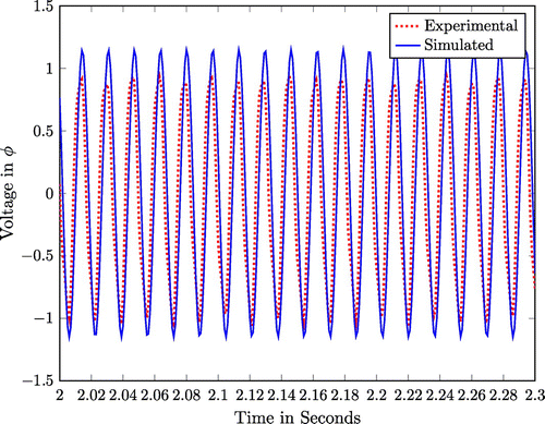
Figure shows the matching between the experimental voltage of the left patch and numerically predicted voltage at successful identification.
12. Conclusions
In this article, a novel structural parameter identification based on voltage matching by using PZT patch sensor is presented. Unlike conventional accelerometer sensor, PZT patch is low cost, negligible weight,wide band width and dynamic measurement of distributed nature. Mathematical model of the PZT sensor with host structure is developed on the basis of one-dimensional geometry and reduced material property. The structural identification is done by the minimization of MSE of the deviation between the measured and predicted voltage responses with unknown structural parameters as optimization variables using PSO. The effect of different PZT length is investigated with numerical example and convergence of the fitness functions of those case are studied. The result shows that identification using PZT:5% (smallest patch length under study) is even sufficient for accurate structural parameter identification and it is successfully verified experimentally. The Mean Absolute Error (PZT:5%) are very low in the range of 0.167–0.959% (noisy condition) for structural parameter identification as compared to other existing methods. It is also used for identifying the crack depth and location accurately with an MAE of 4.8 and 1.63%, respectively, for noisy signal. The PZT method was capable of detecting crack depth more accurately than previous time and frequency domain methods.
Notes
No potential conflict of interest was reported by the authors.
References
- Ghanem R, Shinozuka M. Structural-system identification I: theory. J. Eng. Mech. ASCE. 1995;121:255–264.
- Koh C, See L. Identification and uncertainty estimation of structural parameters. J. Eng. Mech. ASCE. 1994;120:1219–1236.
- Chakraborthy S, Mukhopadhyay M. Estimation of in-plane elastic parameter and stiffner geometry of stiffened plates. J. Sound Vib. 2000;231:99–124.
- Kianian M, Golafshani AA, Ghodrati E. Damage detection of offshore jacket structures using frequency domain selective measurements. J. Mar. Sci. Appl. 2013;12:193–199.
- Yang Z, Wang L. Structural damage detection by changes in natural frequencies. J. Intell. Mater. Syst. Struct. 2010;21:309–319.
- Wang X, Hu N, Fukunaga H, et al. Structural damage identification using static test data and changes in frequencies. Eng. Struct. 2001;23:610–621.
- Liu H, Xin K, Qi Q. Study of structural damage detection with multi-objective function genetic algorithms. Proc. Eng. 2011;12:80–86.
- Kang JS, Park SK, Shin S, et al. Structural system identification in time domain using measured acceleration. J. Sound Vib. 2005;288:215–234.
- Nandakumar P, Shankar K. Structural parameter identification using damped transfer matrix and state vectors. Int. J. Struct. Stab. Dyn. 2013;13:1250076, 27p.
- Koh CG, Chen Y, Liaw C. A hybrid computational strategy for identification of structural parameters. Comput. Struct. 2003;81:107–117.
- Gao F, Lu Y. A kalman-filter based time-domain analysis for structural damage diagnosis with noisy signals. J. Sound Vib. 2006;297:916–930.
- Koh CG, Hong B, Liaw CY. Substructural and progressive structural identification methods. Eng. Struct. 2003;25:1551–1563.
- Varghese CK, Shankar K. Crack identification using combined power flow and acceleration matching technique. Inverse Prob. Sci. Eng. 2012;20:1239–1257.
- Ding Z, Lu Z, Huang M, et al. Improved artificial bee colony algorithm for crack identification in beam using natural frequencies only. Inverse Prob. Sci. Eng. 2016. doi: 10.1080/17415977.2016.1160391.
- Hu L, Huang L, Lu ZR. Crack identification of beam structures using homotopy continuation algorithm. Inverse Prob. Sci. Eng. 2016. doi:10.1080/17415977.2016.1141206.
- Li H. JL, Lu Z. Simultaneous identification of stiffness and damping based on derivatives of eigen-parameters. Struct. Eng. Mech. 2015;55(4):687–702.
- Gounaris GD, Papadopoulos CA, Dimarogonas AD. Crack identification in beams by coupled response measurements. Comput. Struct. 1996;58:299–305.
- Krawczuk M, Zak A, Ostachowicz W. Elastic beam finite element with a transverse elasto-plastic crack. Finite Elem. Anal. Des. 2000;34:61–73.
- Viola E, Federici L, Nobile L. Detection of crack location using cracked beam element method for structural analysis. Theor. Appl. Fract. Mech. 2001;36:23–35.
- Viola E, Nobile L, Federici L. Formulation of cracked beam element for structural analysis. J. Eng. Mech. 2002;12:220–230.
- Sumant PS, Maiti SK. Crack detection in a beam using pzt-sensors. Smart Mater. Struct. 2006;15:695.
- Fukunaga H, Hu N, Chang FK. Structural damage identification using piezoelectric sensors. Inter. J. Solids Struct. 2002;39:393–418.
- Shen MH. A new modeling technique for piezoelectrically actuated beams. Comput. Struct. 1995;57:361–366.
- Bendary IM. MAE, Riad AM. Finite element model of smart beams with distributed piezoelectric actuators. J. Intell. Mater. Syst. Struct. 201021:747-758.
- Zemcik S. Modal analysis of beam with piezoelectric sensors a actuators. Appl. Comput. Mech. 2007;1:381–386.
- Sadilek P, Zemcik R. Frequency response analysis of hybrid piezoelectric cantilever beam. Eng. Mech. 2010;17:73–82.
- Sulbhewar LN, Raveendranath P. A numerically accurate and efficient coupled polynomial field interpolation for euler-bernoulli piezoelectric beam finite element with induced potential effect. J. Intell. Mater. Syst. Struct. 2014; 26(12):1537–1550.
- Benjeddou A. Advances in piezoelectric finite element modeling of adaptive structural elements: a survey. Comput. Struct. 2000;76:347–363.
- Kapuria S, Hagedotn P. Unified efficient layerwise theory for smart beams with segmented extension/shear mode piezoelectric actuators and sensors. J. Mech. Mater. Struct. 2007;2(7):1267–1298.
- Sandesh S, Shankar K. Time domain identification of structural parameters and input time history using a substructural approach. Int. J. Struct. Stab. Dyn. 2009;9:243–265.
- ShengPing LXS. Dynamic analysis of bernoulli-euler piezoelectric nanobeam with electrostatic force. Sci. China Phys. Mech. Astron. 2013;56:1930–1937.
- Tzou H, Tseng C. Distributed piezoelectric sensor/actuator design for dynamic measurement/control of distributed parameter systems: a piezoelectric finite element approach. J. Sound Vib. 1990;138:17–34.
- James K, Eberhart R. Particle swarm optimization. Vol. 4, Proceedings of IEEE International Conference on Neural Networks. 1995; p. 1942–1948.
- Perez R, Behdinan K. Particle swarm approach for structural design optimization. Comput. Struct. 2007;85:1579–1588.
- Sandesh S, Shankar K. Application of a hybrid of particle swarm and genetic algorithm for structural damage detection. Inverse Prob. Sci. Eng. 2010;18:997–1021.
- Mouser CR, Dunn SA. Comparing genetic algorithm and particle swarm optimization for inverse problem. ANZIAM J. 2005;46:89–101.
- Yun CB, Bahng EY. Substructural identification using neural networks. Comput. Struct. 2000;77:41–52.


