 ?Mathematical formulae have been encoded as MathML and are displayed in this HTML version using MathJax in order to improve their display. Uncheck the box to turn MathJax off. This feature requires Javascript. Click on a formula to zoom.
Abstract
Plate- and shell-like elements are the main constituent of many engineering structures such as ships and airplanes. This paper develops a frequency domain model updating method using power spectral density function and seeks its viability in damage identification of plates and shells. The derivation of the sensitivity equation is exact and measured natural frequencies of few lower modes are used to overcome the drawbacks of incomplete measurement. The method is numerically examined in several damage cases. The robustness of method against measurement and mass modelling error is numerically assessed using Monte-Carlo analysis and numerically simulated error contaminated data. The method proves to be robust against both kind of errors and performs well, both in cases of plate and shell elements.
1. Introduction
Plates and shells are widely used for structural applications such as, ships and boats, planes, oil and gas reservoirs, pipelines and bridges. These structures are generally constructed to withstand harsh loading conditions. Most of these structures are intended to carry dangerous and critical fluids. Thus, keeping their integrity in check and monitoring their health is of certain importance. It is promising to detect damages at the earliest possible stage after initiation as it prevents sudden catastrophic structural failure. Among the nondestructive methods for structural inspection, vibration-based methods have known to be capable of diagnosing damage without prior knowledge on its location. In most vibration-based methods, modal data such as natural frequency [Citation1–3], anti-resonance frequencies [Citation4], mode shape [Citation5,6], modal flexibility [Citation7–9], modal strain energy [Citation10–12] as well as Frequency Response Function (FRF) [Citation13–17] have widely been used in model-based and non-model-based damage identification schemes. Modal data (natural frequencies and mode shapes) are inherent structural properties and render great information about structural condition. The accuracy of parameter estimation weakens when the data from fewer lower modes are accessible. In such situations, the frequency domain data are more admissible because they provide data from more frequency points. Availability of data from more frequency points is necessary for robust model updating and solution uniqueness by setting an over-determined equation [Citation18]. Innovative [Citation19,20] or hybrid [Citation21] methods that circumvent the shortcomings of conventional methods are necessary for robust model updating and damage detection using modal data.
The use of vibration-based damage detection methods for plates and shells has recently drawn the attention of researchers [Citation22–25]. Zubaydi et al. [Citation26] used the autocorrelation function to detect damage in stiffened plates. They found the random response metrics suitable for damage detection in plates. Li et al. [Citation11] presented two damage indicator indices namely, bending moment and residual strain mode shape, to locate the damage in plate-like structures. Despite the simplicity of method, some damages at certain locations might not be detected. Wu and Law [Citation27] used incomplete measured mode shape to calculate uniform load surface (ULS) sensitivity for damage detection in plates. They used Chebyshev polynomials of higher order to calculate the sensitivities of ULS. Bayissa and Haritos [Citation28] proposed a non-model-based method for identification and localization of the damage in a plate-like structure using spectral strain energy (SSE). The SSE was derived from moment response power spectral density and curvature power spectral density. They compared their method with modal strain energy (MSE) method proposed by Cornwell et al. [Citation29]. Later Hu et al. [Citation30] extended the use of same method for identifying the damaged regions of cylindrical shells. They numerically tested the damage index for the examples of pipeline structures. Bayissa and Haritos [Citation31] introduced another damage sensitive index based on changes in bending moment power spectral density for plate-like structures. They numerically investigated the method and proved its advantages over changes in natural frequency, modal flexibility and curvature for damage identification. Despite certain advantages of such methods, they need region by region inspection of the whole structure to find the vicinity of damage. Trendafilova and Manoach [Citation32] developed a method based on time series for damage detection and localization in thin plates. Trendafilova et al. [Citation33] applied their method to detect damage in circular plates. Huh et al. [Citation34] introduced a two-dimensional damage index based on vibratory power of plates. The vibratory power of thin plates was calculated based on its response to arbitrary excitations. Wei et al. [Citation20] introduced a two stage damage localization and quantification method based on modal strain energy change ratio (MSECR). They also proposed a novel method to weaken the vicinity effect in localization of damage.
FE model updating using the statistical metrics of structural response such as correlation function and its frequency domain indicator, Power Spectral Density (PSD), have recently been noticed [Citation35,36]. There are a number of advantages for model updating using PSD [Citation35,36]. First, it embraces the data on structural behaviour at wide frequency ranges. Second, it is more sensitive to damage as compared to FRF and modal data. Third, it embraces both auto and cross spectral terms, hence providing more data for model updating. Despite the given advantages of PSD for FE model updating, it has not received enough attention. This is certainly because PSD is a highly sensitive function of structural parameters and the calculation of a reliable linear equation that attributes the changes in PSD to variation of structural parameters is a challenging issue. Hence, some already developed model updating schemes [Citation35–37] resort Taylor series expansion of PSD to develop the sensitivity equation.
This paper presents a model-based damage detection method using PSD function suitable for application to plate- and shell-like structures. A novel sensitivity-based FE model updating method using PSD for damage detection in plates and shells is developed and its challenges are addressed. The sensitivity equation is derived in an exact manner and an approximate formula is used to circumvent the adverse of incomplete measurement. Several damage cases are studied for both kinds of elements and under assumption that only low frequency range data are available. Robustness of method against measurement and mass modelling error is examined by adding random error to simulated PSD of damaged model and mass parameters.
2. Theory
2.1. Development of the sensitivity equation
Power spectral density of structural response subject to multiple stationary excitations is expressed by,(1)
(1)
Where, Ne is the number of excitations, Fi is the mapping matrix consists zero and one. Sffi(ω) is the PSD of ith excitation at ωth frequency. In this equation, Sxx(ω) is the PSD matrix of response in a sense that its diagonal terms are auto spectral density and the non-diagonal ones are cross spectral density terms. The system frequency response function H(ω), is defined as:(2)
(2)
The transfer function H(ω), is nd × nd matrix composed of the system characteristic matrices, mass (M), damping (C) and stiffness (K), and . In order to develop the sensitivity matrix, the Equation (Equation1
(1)
(1) ) is rewritten for the intact (denote by I index) and damaged (denote by D index) states of structure as,
(3)
(3)
(4)
(4)
Damage will cause δM, δK and δC changes in mass, stiffness and damping matrices, respectively. Hence for the damaged structure, Equation (Equation4(4)
(4) ) is stated in the following format,
(5)
(5)
And by further expansion of Equation (Equation4(4)
(4) ), it will transform as,
(6)
(6)
Upon the subtraction of Equation (Equation2(2)
(2) ) from (5), it yields,
(7)
(7)
Finally by substituting Equation (Equation1(1)
(1) ) for damaged state, some mathematical manipulation δZ = δK − ω2δM + iωδC the final expression for the change in the power spectral density is derived as,
(8)
(8)
In this equation, δH(ω) is the change in the reacceptance matrix as expressed in the Appendix.(9)
(9)
By substitution of the transpose of Equation (Equation9(9)
(9) ) in the (8), the change in the spectral density matrix is expressed as
(10)
(10)
The change of PSD with respect to change in stiffness (), mass (
) and damping (
) matrix is expressed using the following equations.
(11)
(11)
(12)
(12)
13)
13)
The above sensitivity relation is solvable using linear least-squares error minimization through an iterative model updating scheme. Moreover, in model updating process, elemental connection and boundary condition type is of certain importance [Citation38]. In this study, it is assumed that the connection between elements and boundary condition is not affected by the damage. In an iterative model updating scheme, change in stiffness, mass and damping matrices are stated as,(14)
(14)
(15)
(15)
(16)
(16)
kn, mn, cn represent the element level stiffness, mass and damping matrices assembled to the global matrix at the nth element DOFs and indicates the normalized damage ratio attributed to the nth elements. The final format of the model updating equation will be,
(17)
(17)
where, Sk, Sm and Sc are the sensitivity of PSD to stiffness, mass and damping parameters.
The developed sensitivity Equation (Equation17(17)
(17) ) should be solved by least-squares method for unknown changes in the structural parameters. It is however, an ill-posed problem. It is worth noting, vibration-based damage detection methods using finite-element model updating engender ill-posed inverse problems, unless special care is given to the well-posedness of method [Citation39]. An ill-posed set of linear equations is solvable if proper side constraint is defined to the problem [Citation40]. In this regard, a set of unprejudiced side constraints are defined to the problem as
. Hence, the inverse problem for damage detection and model updating turns to be,
(18)
(18)
The solution to the above problem is reached by MATLAB’s optimization toolbox through constrained linear least-squares method.
In solving a model updating problem using least-square method, some of the equations with largest coefficients may dominate the solution. In a model updating scheme using frequency domain data, it is possible to weight each equation by the, inverse of the standard deviation of data, the norm of the sensitivity equation, or by the inverse of the excitation frequency (ω−1) [Citation13]. In this paper, each row of the sensitivity is divided by its second norm. Upon implementation of the weighting approach the discrepancy between the impacts of equations on the solution vanishes as the norm of all rows becomes unity. The application of this weighting approach also improves observability of less observable design variables in the model updating process.
2.2. Model updating issues
The success of a model updating scheme based on the frequency domain data depends on the excitation frequency ranges, the number and location of measured and excited DOFs, and the accuracy of the sensitivity equation. The exact sensitivity presented in Equation (Equation8(8)
(8) ) needs the spectral density of damaged structure. Evaluating
necessitates complete measurement of FRF of the damaged structure. In order to avoid the need for measured FRF of damaged structure it is approximated as,
(19)
(19)
The first term consists of measured natural frequencies ΩjD, modal damping loss factors ξjD of the damaged structure at a m lower modes and the corresponding mode shapes of the analytical model ϕjI and ΩjI. The second term consists of the analytical model natural frequencies, damping loss factors and mode shapes of analytical model corresponding to unmeasured modes. The second term is added in order to decrease the adverse impacts of measurement incompleteness in higher frequency ranges. It also helps sensitivity equation to be more precise during the model updating process by updating the modal characteristics of higher modes.
The accuracy of the approximated , calculated by Equation (Equation19
(19)
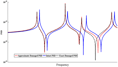
(19) ) is illustrated by comparing it with its exact counterpart for a typical damage case in Figure . The plot presented in Figure proves the ability of Equation (Equation19
(19)
(19) ) in presenting a well-approximate power spectral density of damaged model. It is also evident that the approximation is more precise near measured resonances of damaged model. Due to incorporating modal data of damaged model in the first summation, the approximate PSD is well clear from the PSD of intact model up to the mth natural frequency. Since the approximate formula is controlled by the denominator, so the accuracy of Equation (Equation19
(19)
(19) ) reduces by marching from resonances to anti-resonances.
The appropriate selection of the excitation frequency ranges will result in the smoothness of the optimization process, convergence rate of model updating scheme, reducing the effect of noise on PSD residual. In this study, the frequency ranges in vicinity of resonances are adopted as excitation frequency range. In order to avoid unsmooth behaviour of optimization process, excitation frequencies between natural frequencies of the intact and damaged structure are excluded [Citation14,17,41]. Between natural frequencies of intact and damaged model, the residual between intact and damaged PSD reduces and then increases. Therefore, a smooth reduction of the residual is not possible in successive iterations [Citation41]. At the selected excitation frequency, high accuracy of sensitivity equation and significant difference between the PSD of damaged and intact model decrease negative effect of noise on δSxx. In other word, the frequency ranges where the measurement noise overshadows the residual should be avoided. Furthermore, the frequency ranges with notable effect of damping, on the response of intact model, like at the resonances and anti-resonances should be avoided in order to remove the need for an accurate damping model [Citation42]. The frequency range of interest will be illustrated in next section.
3. Numerical investigations
3.1. Finite element formulation
According to Bathe [Citation44], the displacement field within a shell element is defined by the following displacement field functions.(20)
(20)
(21)
(21)
(22)
(22)
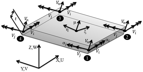
Figure shows a schematic of shell element. The given shape function is suitable for modelling thin to moderately thick shells.
In these equations, nn is the number of nodes, ξ, η, μ are the natural coordinates, u, v, w are the displacement in x, y, z directions and uk, vk, wk are the nodal displacements. Moreover, Nk(ξ, η) is the isoparametric shape function adopted based on the number of nodes within element, tk is the thickness of element at kth node and is the perpendicular unit vector to the shell mid-surface at nodes.
and
are two unit vectors perpendicular to
. Moreover, αi and αj are the rotation about these two vectors, respectively.
3.1.1. Stiffness and mass matrix of plate element
In the case of a plate element the unit vectors are Vi = (1, 0, 0), Vj = (0, 1, 0) and Vn = (0, 0, 1). In other words, they are coincident to X–Y–Z axes. Moreover, αi = ψy and αj = ψx, where ψx and ψy are the rotations about y and x axis. In case of plate elements in-plane displacements are inadmissible and therefore uk = vk = 0, hence making the plate element displacement field become,(23)
(23)
(24)
(24)
(25)
(25)
Equations ((Equation23(23)
(23) )–(Equation25
(25)
(25) )) are the well-known Mindlin–Reissner plate elements shape functions. So, plate element has one transitional (wk) and two rotational (
,
) on each node. A total of twelve DOFs are attributed to each element. For plate elements, the normal (εxx, εyy) and shearing (γxy, γyz, γxz) strains are the admissible components. Normal strain components as well as in-plane shear components (εxx, εyy, γxy) constitute the bending portion of the stiffness matrix and (γyz, γxz) form the shearing portion of the stiffness matrix. So, the stiffness matrix is represented in natural coordinate system as,
(26)
(26)
(27)
(27)
(28)
(28)
(29)
(29)
(30)
(30)
In above equations, E is modulus of elasticity, υ is the poison ratio, κ is the shear correction factor depending on the boundary condition and is the determinant of Jacobin matrix. Bb is the (3*12) bending strain mapping matrix and Bs is the shear strain mapping matrix. N is displacement field to DOF mapping matrix. In case of plate element, the integration with respect to μ is held explicitly and the integration with respect to the other variables is held numerically using Gaussian quadrature integration scheme. In order to avoid the problem of shear locking; the shear portion of stiffness matrix is integrated using less integration points. It is worth noting here, the thickness is considered as uniform in all the nodes in this study.
3.1.2. Stiffness and Mass matrix of shell element
In case of shell element, the element behaviour is influenced by membrane effect in addition to bending and shearing effects. For a shell element, there are 5 degrees of freedom at each node, three transitional (uk, vk and wk) and two rotational (αi and αj). Hence, a 4-node shell element has 20 DOFs. The stiffness matrix of a shell element is introduced as,(31)
(31)
(32)
(32)
(33)
(33)
In this case the integral could not be held explicitly on μ, so triple integral is held numerically to calculate the three above integrals. The first integral is bending, second integral is membrane and the third integral is shear portion of matrix. The bending portion is integrated with 3 * 3 * 3 Gaussian integration scheme and the other integrals are held 2 * 2 * 2 to avoid membrane and shear locking. Further detail about the factors introduced above could be found in Refs. [Citation43–45].
3.2. Measurement and excitation condition
Each excitation at each frequency point will lead to the auto-spectral density (ASD) of the response at each sensor location and cross spectral density (CSD) of the response between the sensors. The data collected by each sensor will lead to Auto-spectrum with itself and Cross-spectrum with the data collected by the other sensors in frequency domain. So, considering nm sensors, the size of PSD matrix is nm × nm. The data on the main diagonal are the ASDs of each sensor with itself. The out of diagonal element of the matrix are the CSDs between the sensors. Since it is a symmetric matrix, the data from the lower triangle are just accounted as,(34)
(34)
Therefore, with nm measured responses, the total number of data points generated at each frequency because of an excitation will be(35)
(35)
Regarding the above-mentioned points, the methods leads to nf × ne × ndata equations to be solved by least-square method. Moreover nf and ne are the number of frequency points and excitation points, respectively. This is one of the major advantages of using PSD for FE model updating rather than FRF. In other words, FRF methods give nm equations for a given excitation at a certain frequency point.
3.3. Damage detection results
3.3.1. Plate example
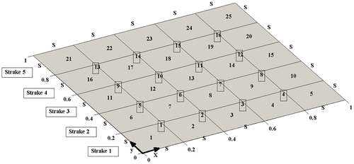
The method is applied numerically to the model of a flat plate with four simply supported edges (SSSS) as depicted in Figure .
The plate is 1 m × 1 m and its finite-element model consists of 25 elements (5 divisions both in x and y direction). Numbers of nodes with active transitional DOFs are shown in Figure . The material of the model is considered to be steel with Young modulus of 200 Gpa, Poisson ratio of 0.3 and mass density of 7800 kgm−3. The uniform thickness of 10 mm is considered for the plate. It is assumed that the structure is excited at nodes 6, 7, 10, 11 and structural responses are measured at 8 measurement location. These points are selected on the transitional DOFs of 2, 3, 5, 9, 8, 12, 14, and 15 nodes. No excitation and measurement is considered for the rotational DOFs.
In order to assess the robustness of the proposed method against measurement errors, 15% random error is added to the simulated PSD data of the damaged model. The simulated PSD of the damaged model is contaminated with noise by adding a certain per cent of normally distributed random error multiplied by the PSD of damaged model as,(36)
(36)
where, Ep is the error percent. Noise is a zero mean normally distributed random error vector. is the simulated PSD of damaged model.
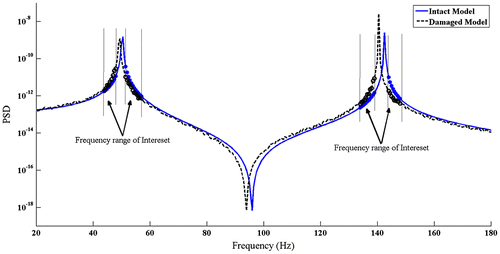
is the simulated PSD of damaged model contaminated with noise. An example of simulated noisy PSD of damaged model is given in Figure . The frequency ranges used for model updating according to Section 2.2, are also marked on this figure. In such ranges, the model updating process is least affected by the measurement noise and the adopted model for damping of intact model.
Fifty sets of the simulated error contaminated PSD data are used to conduct Monte-Carlo simulation. The COV of the predicted parameters is also used to investigate the robustness of the method. The lower COVs of the estimated damage parameters proves the robustness of the method against measurement error. In order to investigate the performance of the proposed method for plate elements, several damage cases with different severities are investigated. The studied damage cases are introduced in the Table .
Table 1. Damage cases studied for plate example.
In this study, in order to probe the method in practical condition, lower frequency range is considered for model updating. In this regard, the frequency range of interest is selected around the first six natural frequencies. The natural frequencies of intact and damaged plate models are summarized in Table . Moreover, the excitation frequency ranges used for model updating are given in the last column of this table.
Table 2. Natural frequencies and excitation frequency ranges (Hz)for considered damage case.
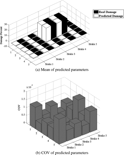
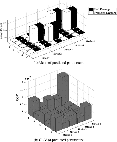
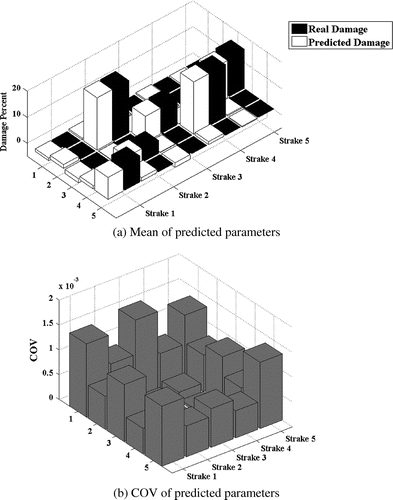
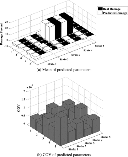
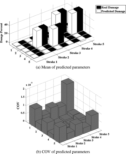
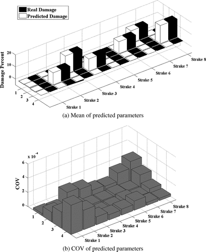
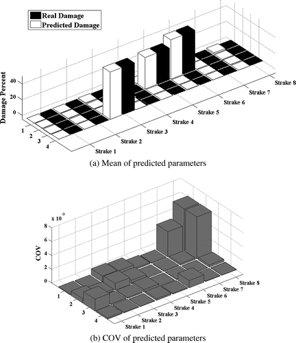
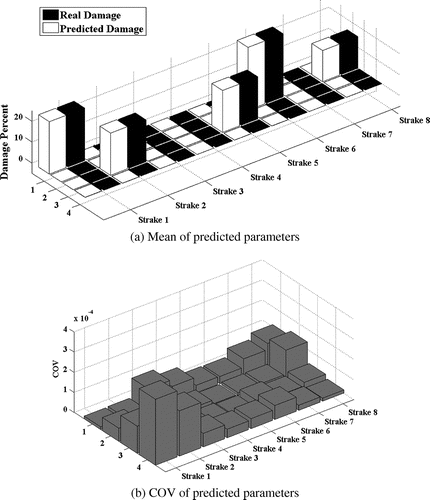
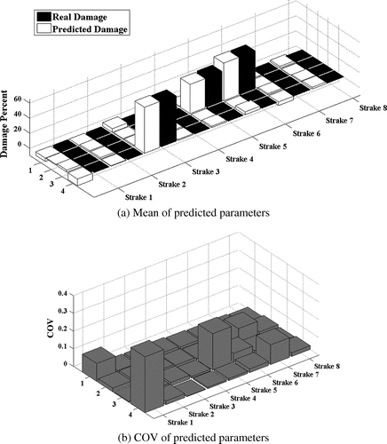
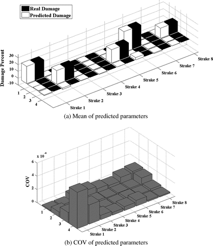
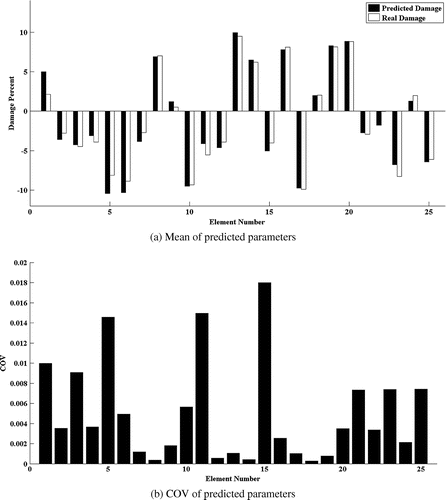
The model updating results of three damage scenarios are presented in Figures . Parts (a) of these figures present the mean of the parameter estimation results, while part (b) shows the COV of the estimated parameters.
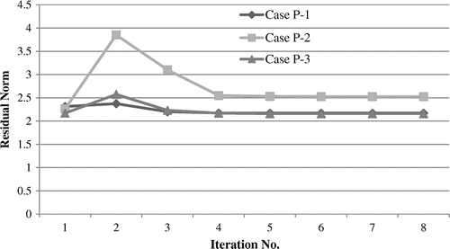
Close values of the predicted and actual damage parameters; demonstrate that the method is capable of localization and quantification of damage irrelevant to the location of damaged elements. The norm of the residual ||δSxx − Sk . dk||2 for the studied damage cases is plotted in Figure . As this figure shows, the method exhibits a fast convergence rate. It is worth noting that due to presence of noise the residual cannot reach to zero in the model updating process.
3.3.1.1. Mass modelling errors
Mass matrix is the discrete representation of the distributed structural mass [Citation45]. There is a possibility that the developed mass matrix is not the perfect representation of the structural inertia. On, the other hand, quality of mass parameters used for modelling the inertia properties of the structure is critical to the accuracy of the method. In order to simulate inaccuracy in mass matrix 10% random error in mass parameters of the model is considered and P-2 and P-3 damage case are reinvestigated. Predicted damage parameters are given in Figures and . By comparing the results in Figures and with Figures and , it is understood that incorporation of mass parameter errors will not affect the robustness of the method.
3.3.2. Shell example
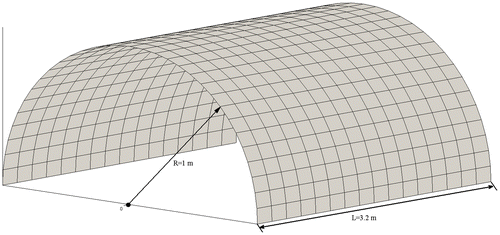
Shells are widely used in the construction of various engineering structures. So, in this section the performance of method is investigated in such cases. A half cylinder with 3.2 m length and 1 m radius as depicted in Figure is considered for numerical investigation.
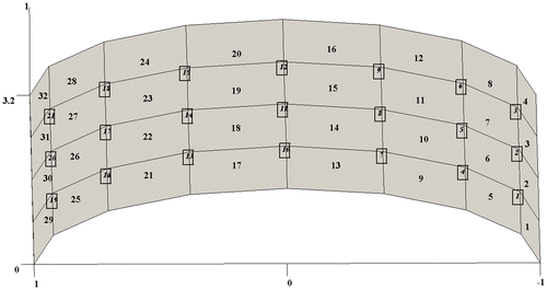
All edges of the model are considered to be clamped. The material properties of steel same as plate example are considered here with the thickness of 10 mm. According to Figure , model is discretized by 32, 4-node elements. With the considered boundary conditions it has 21 active nodes. Having 5 DOFs at each node, the model has 105 active DOFs. The transitional DOFs normal to the element surface on nodes 8, 10, 12 and14 are considered as excitation points. Eighteen considered measurement locations are selected among the transitional DOFs at three directions. Transitions of nodes 1, 9, 13 and 2 in X direction, Transitions of nodes 5, 11 and 17 in Y direction and Transitions of nodes 1, 3, 5, 7, 9, 11, 13, 15, 17, 19 and 21 in Z direction are the selected measurement locations. In order to investigate the performance of the proposed method for shell elements, several damage cases with different severities are investigated. The studied damage cases are introduced in the Table .
Table 3. Damage cases studied for shell example.
The first six lowest natural frequencies are assumed as measured and excitation frequency ranges for model updating are considered around them. The natural frequencies of the shell model in intact and damaged cases, as well as excitation frequency ranges for model updating are listed in Table .
Table 4. Natural frequencies and excitation frequency ranges (Hz) for considered damage cases.
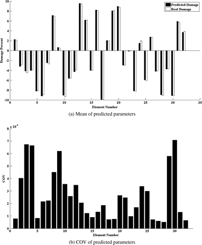
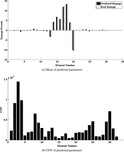
The model updating results are presented in Figure through . The results show robust localization and quantification of structural damages in case of shell structure.
3.3.2.1. Mass modelling errors
Assuming 10% random error in mass parameter of the model, Sh-2 and Sh-3 damage case are reinvestigated. Presented results in Figures and show that the method can withstand the adverse effects of the above-mentioned errors.
3.3.3. Zone damage and distributed damage
In this section, three cases of zone damage (damage in a portion of elements) and deterioration damage are investigated for plate and shell model. Occurrence of such damage cases is very probable in the highly corrosive environments such as marine and offshore. These damage cases are produced by adding up to 10% random changes to the stiffness parameters. For better illustration and readability of results, linear bar chart representation is adopted here. The method proves to be successful in such cases as presented in Figures .
4. Effect of frequency ranges on the observability of elements
By using frequency domain representation of structural responses by PSD or FRF adequate data are available to perform model updating in wide frequency ranges. This is an advantage in case of shell- and plate-like structures. Generally it is indicated that higher frequency ranges data are more sensitive to structural damages and are recommended for model updating. However, for flexural elements like plates and shells more insight must be attended to this issue. Because, By selecting the structural response at higher frequency ranges, the number of low amplitude vibrating DOFs will increase, which leads to low sensitivity of the selected metric to change of structural parameters. In order to demonstrate this, the studied damage cases are reconsidered here.
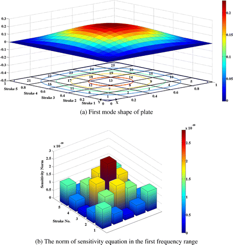
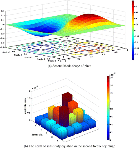
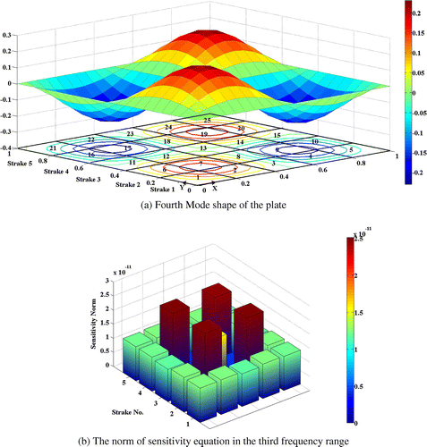
Among the frequency ranges introduced in Table for each damage case, four frequency ranges are considered to as given in the Table to investigate the effect of frequency ranges. For the plate model with SSSS boundary condition as it is given in Table , second and third natural frequencies, as well as fifth and sixth natural frequencies are coincident in the same frequency. For each damage case, the first frequency range is in the vicinity of first natural frequency. Second range is in the vicinity of second and third natural frequencies. Third range is around the forth natural frequency and forth range is near fifth and sixth natural frequencies. The mode shape corresponding to the selected excitation frequency ranges and of norm of sensitivity equation columns are plotted in the Figures . Norm of the sensitivity matrix’s columns is evaluated as a measure of element observability.
Table 5. Study frequency ranges for damage cases.
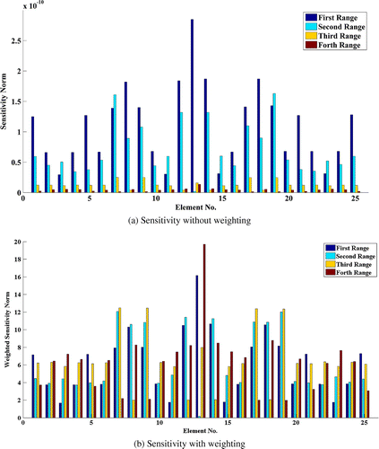
From these figures, it is discerned that, design variables relevant to elements at higher curvature, exhibit more observability as compared to other elements. Furthermore, elements located on the null point of the corresponding mode shape, represent the minimum observability in related excitation frequency ranges. The other elements are moderately observable. In brief as the number of null points in a mode shape increases, the number of low observable elements in the frequency ranges of its vicinity will increase too. In order to compare the observability of the elements regarding the selected frequency range, the norms of the sensitivities matrix before and after weighting are plotted simultaneously in a bar chart plot of Figure for P-1 damage case. This comparison shows that as marching from low frequency ranges toward the high frequency ranges, the sensitivity of the metric to change of structural parameters drastically reduces. So, it is advantageous to consider low frequency ranges for model updating of plates.
The effect of weighting approach on the observability of design variables in the study frequency ranges is the other matter discussed here. Norm of the weighted sensitivity is also plotted in Figure (b). The weighting approach does not affect the sensitivity of an element with respect to other elements in a frequency range. However, the significant difference between the sensitivity norms of elements before weighting is eliminated after weighting (Figure (a) and (b)). Thus, a balanced effect of the frequency ranges on the results is expected by application of weighting. The same study is done in the case of shell model and the same observations are made. Yet, the results are not presented to avoid repeated discussions.
5. Discussion
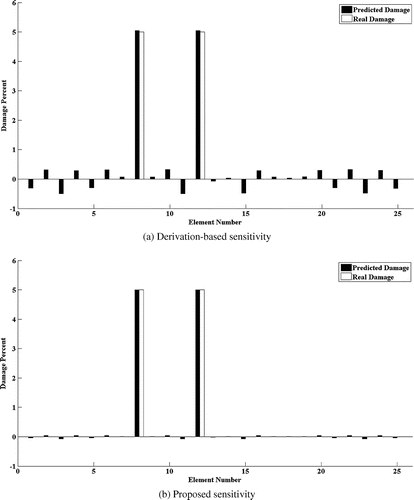
In order to calculate the sensitivity of PSD it is also possible to adopt first order Taylor series expansion. The Derivation-based sensitivity of PSD is given in the following equation.(37)
(37)
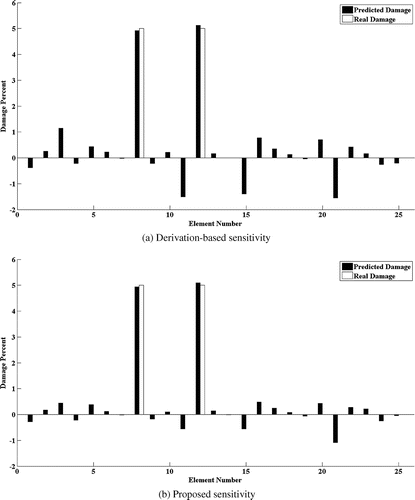
A comparison case of slight damage in elements 8 and 12 of plate model is considered to highlight the merits of exact sensitivity equation. The results presented in Figure , proves that with the same condition in term of excitation frequency range, measurement and excitation location and upper and lower bounds the exact method exhibits more precise solution of the comparison case in the noise-free situation.
The robustness of both sensitivity equations is also tested in presence of 5% random noise in simulated PSD of damaged model. The damage detection by Monte-Carlo analysis of simulated noisy sets proves that the exact method leads to more precise results as compared to derivation-based method. The Closeness Index (CI) of the comparison case in both conditions is given in the Table . According to definition [Citation15], the closer the CI is to 1 the more precise the solution is. It is worth noting here, the derivation-based method does not converge to a solution in case of all the studied cases before and in presence of higher level of noise. The comparison of the mean parameter estimation results is given in the Figure .
Table 6. Closeness index for comparison case.
6. Conclusion
Most structures comprised of shell and plate elements should withstand harsh loading situation in their lifetime. Using PSD as metric, this paper presents a FE model updating method and investigates its performance in case of plate and shell models. The sensitivity equation is derived in an exact manner and an approximate formula is used to overcome incomplete measurement adversities. Several damage cases are studied for both kinds of elements in low frequency range and under assumption that only the first few natural frequency of damaged models is available. Damage cases test the performance of method against different level and location of damage. The method is successfully applied to both models considering the adverse effects of incomplete measurement both in spatial coordinate and modal parameters. The amount of equations that are provided enables the method to work at low frequency ranges. The method converges to high quality results using six lowest natural frequencies and selecting excitation frequency ranges up to this level. The method proves to be robust against measurement and mass modelling error.
Disclosure statement
No potential conflict of interest was reported by the authors.
References
- Hassiotis S. Identification of damage using natural frequencies and Markov parameters. Comput Struct. 2000;74:365–373.
- Soares CM, De Freitas MM, Araújo A, et al. Identification of material properties of composite plate specimens. Compos Struct. 1993;25:277–285.
- Bicanic N, Chen HP. Damage identification in framed structures using natural frequencies. Int J Numer Method Eng. 1997;40:4451–4468.10.1002/(ISSN)1097-0207
- Arora V. Constrained antiresonance frequencies-based model updating method for better matching of FRFs. Inverse Prob Sci Eng. 2014;22:873–888.
- Dos Santos JA, Soares CM, Soares CM, et al. Structural damage identification: influence of model incompleteness and errors. Compos Struct. 2003;62:303–313.
- Chen H-P, Maung TS. Regularised finite element model updating using measured incomplete modal data. J Sound Vib. 2014;333:5566–5582.
- Yan W-J, Ren W-X. Closed-form modal flexibility sensitivity and its application to structural damage detection without modal truncation error. J Vib Control. 2014;20:1816–1830.
- Sung S, Koo K, Jung H. Modal flexibility-based damage detection of cantilever beam-type structures using baseline modification. J Sound Vib. 2014;333:4123–4138.
- Seyedpoor S, Montazer M. A damage identification method for truss structures using a flexibility-based damage probability index and differential evolution algorithm. Inverse Prob Sci Eng. 2015;1303–1322.
- Srinivas V, Ramanjaneyulu K, Jeyasehar CA. Multi-stage approach for structural damage identification using modal strain energy and evolutionary optimization techniques. Structural Health Monitoring. 2011;10:219–230.10.1177/1475921710373291
- Li Y, Cheng L, Yam L, et al. Identification of damage locations for plate-like structures using damage sensitive indices: strain modal approach. Comput Struct. 2002;80:1881–1894.10.1016/S0045-7949(02)00209-2
- Cha YJ, Buyukozturk O. Structural damage detection using modal strain energy and hybrid multiobjective optimization. Computer-Aided Civil and Infrastructure Engineering. 2015;30:347–358.10.1111/mice.2015.30.issue-5
- Esfandiari A, Bakhtiari-Nejad F, Sanayei M, et al. Structural finite element model updating using transfer function data. Comput Struct. 2010;88:54–64.10.1016/j.compstruc.2009.09.004
- Gang X, Chai S, Allemang RJ, et al. A new iterative model updating method using incomplete frequency response function data. J Sound Vib. 2014;333:2443–2453.10.1016/j.jsv.2013.12.008
- Dos Santos JA, Soares CM, Soares CM, et al. Structural damage identification in laminated structures using FRF data. Compos Struct. 2005;67:239–249.10.1016/j.compstruct.2004.09.011
- Sipple JD, Sanayei M. Finite element model updating using frequency response functions and numerical sensitivities. Struct Control Health Monitoring. 2014;21:784–802.
- Sanayei M, Esfandiari A, Rahai A, et al. Quasi-linear sensitivity-based structural model updating using experimental transfer functions. Struct Health Monitoring. 2012;11(6):656–670.
- Modak S, Kundra T, Nakra B. Comparative study of model updating methods using simulated experimental data. Comput Struct. 2002;80:437–447.10.1016/S0045-7949(02)00017-2
- Esfandiari A. An innovative sensitivity-based method for structural model updating using incomplete modal data. Struct Control Health Monitoring. 2016;24(4): DOI: 10.1002/stc.1905
- Wei Z, Liu J, Lu Z. Damage identification in plates based on the ratio of modal strain energy change and sensitivity analysis. Inverse Prob Sci Eng. 2016;24:265–283.10.1080/17415977.2015.1017489
- Nobari AS, Farjoo MA. Comparison between dedicated model updating methods and hybrid method. J Aircraft. 2004;41:999–1004.10.2514/1.260
- Fu Y, Lu Z, Liu J. Damage identification in plates using finite element model updating in time domain. J Sound Vib. 2013;332:7018–7032.10.1016/j.jsv.2013.08.028
- Cawley P, Adams R. The location of defects in structures from measurements of natural frequencies. J Strain Anal Eng Des. 1979;14:49–57.
- Ip K-H, Tse P-C. Locating damage in circular cylindrical composite shells based on frequency sensitivities and mode shapes. Eur J Mech-A/Solids. 2002;21:615–628.
- Messina A, Williams E, Contursi T. Structural damage detection by a sensitivity and statistical-based method. J Sound Vib. 1998;216:791–808.
- Zubaydi A, Haddara M, Swamidas A. On the use of the autocorrelation function to identify the damage in the side shell of a ship’s hull. Marine Struct. 2000;13:537–551.10.1016/S0951-8339(00)00023-X
- Wu D, Law S. Sensitivity of uniform load surface curvature for damage identification in plate structures. J Vib Acoust. 2005;127:84–92.10.1115/1.1857918
- Bayissa W, Haritos N. Structural damage identification in plates using spectral strain energy analysis. J Sound Vib. 2007;307:226–249.
- Cornwell P, Doebling SW, Farrar CR. Application of the strain energy damage detection method to plate-like structures. J Sound Vib. 1999;224:359–374.10.1006/jsvi.1999.2163
- Hu M-H, Tu S-T, Xuan F-Z, et al. Strain energy numerical technique for structural damage detection. Appl Math Comput. 2012;219:2424–2431.
- Bayissa W, Haritos N. Damage identification in plate-like structures using bending moment response power spectral density. Struct Health Monitoring. 2007;6:5–24.
- Trendafilova I, Manoach E. Vibration-based damage detection in plates by using time series analysis. Mech Syst Signal Process. 2008;22:1092–1106.10.1016/j.ymssp.2007.11.020
- Trendafoilova I, Gorman D, Manoach E. An investigation on vibration-based damage detection in circular plates. Struct. Health Monitoring. 2009;8:291–302.10.1177/1475921708102107
- Huh YC, Chung TY, Lee JW, et al. Damage identification in plates using vibratory power estimated from measured accelerations. J Sound Vib. 2015;336:106–131.10.1016/j.jsv.2014.10.003
- Kammer DC, Nimityongskul S. Frequency band averaging of spectral densities for updating finite element models. J Vib Acoust. 2009;131:041007.
- Pedram M, Esfandiari A, Shadan F. Finite element model updating using power spectral density of structural response; Jul 2014, Nantes, France; 2014.
- Zheng Z, Lu Z, Chen W, et al. Structural damage identification based on power spectral density sensitivity analysis of dynamic responses. Comput Struct. 2015;146:176–184.10.1016/j.compstruc.2014.10.011
- Wang S. Model updating and parameters estimation incorporating flexible joints and boundary conditions. Inverse Prob Sci Eng. 2014;22:727–745.10.1080/17415977.2013.823413
- Xiang Z, Wang L, Zhou M. Suppressing damage identification errors from selected natural frequencies and mode shape points. Inverse Prob Sci Eng. 2012;20:871–890.10.1080/17415977.2011.589902
- Hansen PC. Regularization tools: a Matlab package for analysis and solution of discrete ill-posed problems. Numer Algorithms. 1994;6:1–35.10.1007/BF02149761
- Esfandiari A, Sanayei M, Bakhtiari-Nejad F, et al. Finite element model updating using frequency response function of incomplete strain data. AIAA J. 2010;48:1420–1433.10.2514/1.J050039
- Inman DJ, Singh RC. Engineering vibration. Upper Saddle River: Prentice Hall; 2001.
- Kant T, Kumar S, Singh U. Shell dynamics with three-dimensional degenerate finite elements. Comput Struct. 1994;50:135–146.10.1016/0045-7949(94)90444-8
- Bathe K-J. Finite element procedures. Klaus-Jurgen Bathe; USA: Massachusetts Institute of Technology; 2006.
- Cook RD. Concepts and applications of finite element analysis. Wisconsin, Madison: John Wiley & Sons; 2007.
Appendix 1
The change of the FRF due to the damage in the structural elements is formulated in the following manner. The equation of motion of a MDOF structural system is,(A.1)
(A.1)
Due to the damage the equation of motion becomes,(A.2)
(A.2)
Expansion of the Equation (EquationA.2(A.2)
(A.2) ) and subtracting Equation (EquationA.1
(A.1)
(A.1) ) from it yields,
(A.3)
(A.3)
This by assuming the same loading condition for the intact and damaged structure will transform as, which expresses the change of FRF due to damage.(A.4)
(A.4)

