
 ?Mathematical formulae have been encoded as MathML and are displayed in this HTML version using MathJax in order to improve their display. Uncheck the box to turn MathJax off. This feature requires Javascript. Click on a formula to zoom.
Abstract
The supersonic acoustic intensity is a technique utilized to locate radiating sound regions on a complex vibrating structure. This technology is based on the accurate identification of the supersonic components (or stability regions) of the acoustic field. The identification of these supersonic components is well understood for separable geometries, but unfortunately, there are few results for arbitrarily shaped objects. This work proposes a methodology that efficiently identifies the supersonic components from acoustic pressure measurements. The methodology is based on the spectral decomposition of the power operator that yields a non-negative intensity expression. We will demonstrate using numerical data that the resultant non-negative intensity matches the supersonic intensity.
1. Introduction
1.1. Overview
In the structural acoustic study of a complex vibrating object, it is commonly assumed that the radiated sound mainly contains supersonic and subsonic components. The supersonic components are composed of non-evanescent waves that travel unchanged from the near-field into the far-field, and the subsonic components are composed of evanescent waves that decay exponentially but produce high resolution intensity images at the surface of the structure. The later components have little contribution to the far-field radiation because of their evanescent nature. The resultant intensity image from the supersonic components on the surface of the structure is generally only positive, representing outgoing power flow from the surface. Since negative intensity regions of a vibrator are removed, sources of radiation are readily located on the surface of the vibrator. For that reason, a detailed study of the acoustic radiation will mainly focus on the use of supersonic components and the resultant intensity from these components is known as supersonic intensity. The use of the supersonic intensity images allows the correct identification of radiation regions and quantification of the strength of these regions.
Supersonic intensity was introduced in 1995 (see [Citation1]). This technique was the result of the study of radiation from submerged cylindrical shells and the need to locate the radiating regions on the surface of these shells. The theory was formulated for planar surfaces in [Citation2] using the well-known k-space results from the Fourier Transform (FT). In the k-space, the supersonic components are located inside the circle of radius k and the subsonic components outside. The k-space filter limits the resolution of the intensity image to half wavelength of a given frequency. The k-space that results from the FT has been successfully translated to separable surfaces of the wave equation (planes, cylinders and spheres) but cannot be translated directly into arbitrarily shaped surfaces. For arbitrarily shaped surfaces the acoustic field is represented by the numerical discretization of surface integrals and we can expect that the singular value decomposition (SVD), as the FT, will provide an insight about the filtering of the subsonic components. Indeed, it was experimentally shown in [Citation3] that the SVD share some characteristics with the k-space of planar surfaces. Despite the importance of this result, in practice it is highly difficult to develop an efficient numerical methodology that uses this separation methodology. We can find some interesting attempts of this filter methodology in the works of Magalhâes [Citation4], Tenenbaum [Citation5] and Correa [Citation6]. A slight different approach using non-negative functions to approximate the intensity have been proposed [Citation7,Citation8].
Recently we proposed an efficient numerical methodology for the calculation of the supersonic intensity over arbitrarily shaped geometries [Citation9]. This methodology is based on the spectral properties of the power operator and a rule designed to locate the supersonic radiation modes. Although proven to be effective, the rule used to identify supersonic modes was ad-hoc and still requires more theoretical justification. In this work we extend the results in [Citation9] by providing some explicit integral formulations for the power operator and an expression to the supersonic intensity.
1.2. Integral representations of radiating waves
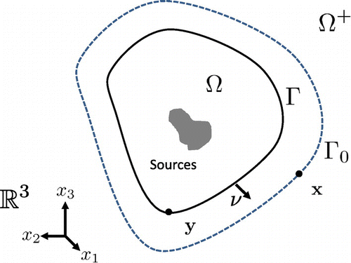
Assume that represents a complex vibrating structure,
its corresponding boundary and
is connected. Let
be a bounded domain that contains
and let
be its corresponding boundary (see Figure ). For a steady-state acoustic wave p with time dependence
, where
is the angular frequency, its radiating behaviour in an homogeneous medium is modelled by the Helmholtz equation
(1)
(1)
where ,
is the wave number and c is the speed of sound in the medium. The radiating wave in (Equation1
(1)
(1) ) follows the far-field behaviour
(2)
(2)
where is known as the far-field pattern of p.
Figure 1. Setup for exterior radiation problem.
For the radiation problems the Direct formulation represents the acoustic wave using the Helmholtz–Kirchhoff integral equation(3)
(3)
where we follow the notation of [Citation10], for the single and double layer operators S and K(4)
(4)
where(5)
(5)
is the free space radiating fundamental solution to the Helmholtz equation. In (Equation4(4)
(4) ),
is the outward unit normal and the jump relations [Citation10] when
yield
(6)
(6)
The indirect formulations are based on representations to the solution of (Equation1(1)
(1) ) like the single layer representation of p (see [Citation11–Citation13])
(7)
(7)
where is known as the source density.
1.3. Radiation theory
The classical structural acoustic theory (see [Citation14,Citation15]) assumes that the radiating sound pressure p results from the interaction between the structure vibration and the normal derivative of the acoustic pressure
. This interaction is modelled by Euler’s equation
(8)
(8)
where is the medium density. The acoustic pressure p is given in
units and the normal velocity
in
units. Using (Equation8
(8)
(8) ), the total power that radiates from the surface
, for the wave p, is given by
(9)
(9)
By this definition we can understand the normal intensity as
as a power density quantification over the surface of the vibrating structure . The resultant units of power are
and the intensity have
units.
For the inverse problem of wave continuation [Citation16] or Near-field Acoustical Holography (NAH) [Citation17] there are acoustic sensors located over the surface which (ideally) is close and conformal to the vibrating structure
. For this inverse problem we want to reconstruct the complete acoustic field (pressure, velocity and intensity) at the surface
from the measurements at
. The single layer representation of p, reduces NAH to the solution of the surface integral equation in (Equation7
(7)
(7) ) for
. Then the reconstructions of p and
at
will be given by
(10)
(10)
For the single layer representation (Equation7(7)
(7) ) of the acoustic wave p, the radiated power is given by
(11)
(11)
where P is known as the power operator. From this representation, we have the explicit expression for the normal intensity(12)
(12)
The normal intensity shows the distribution of the acoustic energy at the radiating surface. A positive value of the intensity means energy leaving the surface (in direction of the normal), while negative values means energy entering the structure (in opposite direction of the normal).
The NAH technique have been develop to reconstruct high resolution images (resolution higher than half the frequency wave-length), but for certain applications these images are not advantageous. In applications like early sound control (specially over realistic radiating structures), we need to identify radiation regions or regions were the sound radiate into the far-field. The identification of these region can be challenging since we encounter complex combinations of negative and positive intensity values (as seen in Figure ). If we move away from the structure, the intensity values ‘short circuits’ and we only encounter positive values that correspond to the radiation region (see [Citation14]). The normal intensity in the form of (Equation12(12)
(12) ) can contain both positive and negative values, but as mentioned above it will be more advantageous to find a non-negative expression to the normal intensity that could potentially reveal the radiation regions. The main result of our work that results from Sections 2 and 3 will be the expression for the ‘supersonic’ intensity
(13)
(13)
for an operator . Notice that this expression for the supersonic intensity yields a non-negative intensity, and this expression will match the same power as in (Equation11
(11)
(11) ).
2. Power operator representations
2.1. Mathematical preliminaries
A Lipschitz surface , means that
is locally the graph of a Lipschitz function. A surface
is
if is a locally graph of functions where the rth derivative is Lipschitz. We will assume that
is Lipschitz and
with connected
. Recall that
denotes the Sobolev space of functions on
whose partial derivatives up to order s are square integrable and
denotes the standard norm in this space. Similarly
denotes the space of functions are
for every ball B that contains
. We let
be the norm in the space
.
Finally we define the inner product between trace functions and
with .
We will use the following useful results that can be found in the acoustic literature. Assume that is a solution to the Helmholtz Equation (Equation1
(1)
(1) ) with
and Sommerfeld radiation conditions (Equation1
(1)
(1) ). For the following lemmas let
be a bounded domain with Lipchitz boundary. Assume that
contains
. We denote as
the ball with center in the origin and radius
. Similarly
is the boundary of
.
Lemma 2.1:
We define as the conservation of power the following property(14)
(14)
ProofFor the proof we refer to [Citation18].
Lemma 2.2:
We have the following trace estimates(15)
(15)
ProofAssume that is the outward normal of
, then the normal velocity assumes the relation (Equation8
(8)
(8) ). For
its trivial to obtain the relation
then
Then integration over , the Sommerfeld radiation condition and the conservation of power yields the results in (Equation15
(15)
(15) ).
For the following result we will utilize the spherical harmonics, which are defined as(16)
(16)
for and
, where
and
is the associated Legendre function. It is well-known that the spherical harmonics form an orthonormal basis at the surface of the unit sphere
, moreover at
where is the Kronecker delta function. The radiating solution p can be represented in
(see [Citation19]) as
(17)
(17)
where is the spherical Hankel function of the first kind. This representation yields the explicit expression for the power (see [Citation14, Chapter 6])
(18)
(18)
Lemma 2.3:
The relation between the power and the far-field is given by(19)
(19)
ProofIntegrating over a ball that contains
, and using conservation of power Lemma 2.1 we get that
. The asymptotic behaviour of the spherical Hankel functions
joined with the spherical representation (Equation17(17)
(17) ) we obtain directly the behaviour for the normal velocity
(20)
(20)
The results in (Equation19(19)
(19) ) follows from using the previous result in Lemma 2.2.
Lemma 2.4:
The acoustical power is positive, moreover if
then
in
.
ProofThis result from the representation (Equation18(18)
(18) ) and Rellich’s lemma (see [Citation19]).
Lemma 2.5:
For , we have the following mapping properties
(21)
(21)
If is of class
for an integer
, then (Equation21
(21)
(21) ) and (Equation22
(22)
(22) ) hold for
.
ProofThis result follows directly from [Citation20, Theorem 7.1,7.2].
Notice that S is a self-adjoint operator, while . This will be used in the following result:
Theorem 2.6:
For , the single layer representation (Equation7
(7)
(7) ) with
yields the power operator
in (Equation11
(11)
(11) ), with the representation
(22)
(22)
ProofNotice the operator relations for
From Lemma 2.5 we obtain that the operators and
map
to
, then (Equation22
(22)
(22) ) follows.
Lemma 2.7:
For the single layer representation (Equation7
(7)
(7) ) yields
(23)
(23)
where the power operator is defined as the integral operator
where(24)
(24)
ProofUsing the single layer representation (Equation7(7)
(7) ), we can change the order of integration to obtain the relation
Changing variables and the order of integration, we obtain (Equation24(24)
(24) ).
2.2. Representation formulas on an infinite medium
For the following theorem we use the result given in Chapter 7 of [Citation21](25)
(25)
where is the spherical bessel function.
Theorem 2.8:
The single source representation (Equation7(7)
(7) ) for a density
yields the integral representation of the power operator in (Equation11
(11)
(11) )
(26)
(26)
ProofAssume that is a ball with radius
such that
then Lemmas 2.1 and 2.7 yield that
Assume that , then notice that
and
then we have the representation
We use these decomposition over the integral representation of in (Equation24
(24)
(24) ) to obtain
and
Since from Lemma 1.2, and r can be arbitrarily large, we let
then
Finally we use (Equation25(25)
(25) ) to obtain (Equation26
(26)
(26) ).
Corollary 2.9:
Assume that is of class
, then the power operator
from the single layer representation (Equation7
(7)
(7) ) is a compact positive definite operator. If k is not a Dirichlet eigenvalue of
then P is strictly positive.
ProofFrom Theorem 2.6 we obtain that . By compact embedding theorems then we obtain the compactness of P. Lemma 2.4 yields that the power operator is positive definite and when k is not a Dirichlet eigenvalue, the uniqueness of the single layer representation guarantees that the operator is strictly positive definite.
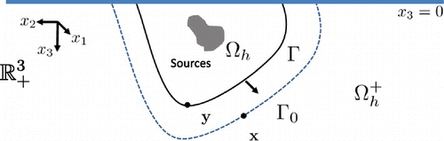
2.3. Representation formulas on a half-space medium
In the previous subsection we focus our analysis of the power operator in an infinite medium. For many acoustical applications it will be a substantial simplification to assume predefined interface conditions over a medium. Let consider the information of the problem be given over and
then we denote
,
and
(see Figure ).
Figure 2. Half space radiation problem.
The boundary layer operators (Equation4(4)
(4) ) and (Equation6
(6)
(6) ) over
are defined by replacing the fundamental solution
by
(27)
(27)
The function is the fundamental solution to the half-space Helmholtz equation with
for sound-soft interface or
sound-hard interface. The sound soft condition is generally used for underwater problems where we assume that the pressure field is 0 at the air-water interface. Similarly the sound hard condition is used when we assume that the object is laying over a wall or hard object where the normal velocity is 0 at the interface.
For , a ball of radius
, denote
.
Lemma 2.10:
We have the following relations(28)
(28)
(29)
(29)
(30)
(30)
ProofFrom [Citation22, Section 12.5] we get that then (Equation28
(28)
(28) ) and (Equation29
(29)
(29) ) follows from the definition of the spherical harmonics. Similarly
then (Equation30(30)
(30) ) follows.
Theorem 2.11:
The single source representation (Equation7(7)
(7) ) for the half-space
for a density
yields the integral representation of the power operator in (Equation11
(11)
(11) )
(31)
(31)
ProofWe proceed as Theorem 2.8, where
for any domain that contains
and have connected
. Assume that
is a ball
for some
. Since
contains
then
and
then we have the spherical harmonic representation representations
This yields the representation
and the fact that can be arbitrarily large, we conclude formula (Equation31
(31)
(31) ).
3. Numerical methodology
3.1. Spectral decomposition
In this section we will use the spectral decomposition of the power operator P to construct an explicit formula for the supersonic intensity. Assume that k is not a Dirichlet eigenvalue then by Corollary 2.9 we get that P is an strictly positive definite operator. By the Hilbert–Schmidt theorem there exist a complete ortho-normal basis in
, such that
(32)
(32)
and as
. Moreover, for any
we have the decomposition
(33)
(33)
where the series is absolutely convergent, i.e.
These functions are known as the power modes [Citation9]. From this result we get that
Theorem 3.1:
Given a function then the total radiated power from the single source representation (Equation7
(7)
(7) ) is given by
(34)
(34)
and there is an expression for the intensity where
(35)
(35)
ProofIs trivial to obtain (Equation34(34)
(34) ) using (Equation33
(33)
(33) ). Notice that
which yields (Equation35(35)
(35) ).
The following corollary follows directly from Theorem 3.1.
Corollary 3.2:
Given a function there exists a non-negative expression for the intensity (Equation13
(13)
(13) ) from the single source representation (Equation7
(7)
(7) ) where
3.2. Boundary element methods
The numerical methodology will require the numerical discretization of the different surface integral equations introduced in the previous sections. We choose the Boundary Element Methods (BEM) to produce these discretization, since it is the classical accurate numerical methodology in the area of acoustics (see [Citation12,Citation23,Citation24]).
Assume that the pressure measurements are given by over m points over the measurement surface
and define as
the pressure and normal velocity over n points in the vibrating surface
. Similarly we define
the density
in (Equation7
(7)
(7) ), (Equation10
(10)
(10) ) over
. Moreover
is decomposed into triangular elements with three nodes. In this paper (as recommended in [Citation23]), iso-parametric linear functions are selected for interpolating the integral quantity
. Denote as
the BEM discretization of the operator S in (Equation4
(4)
(4) ) for
. Similarly
are, respectively, the singular operators
in (Equation10
(10)
(10) ). In addition define as
the discretization of the power operator P in (Equation26
(26)
(26) ).
The numerical application of the NAH technique is reduced to the solution of the matrix equation(36)
(36)
The reconstructed pressure and velocity
in
is given by the relations (Equation7
(7)
(7) ) or
(37)
(37)
and the corresponding normal intensity. An evenly distribution of points on the vibrating surface
can be used to produce a triangular surface element decomposition. Basic BEM calculations over the resultant surface element decomposition produces integration weights
(see [Citation25]),
such that
The power is approximated directly from(38)
(38)
where .
Since is the discretization of a compact positive definite operator we will have the corresponding numerical eigenvalue decomposition
(39)
(39)
where ,
is a set of orthonormal vectors. The numerical identification of the supersonic field from pressure measurements in
is reduced to the solution of
(40)
(40)
The resultant solution of (Equation40(40)
(40) ) is given by
then as (Equation35(35)
(35) ) we represent the supersonic density and corresponding supersonic intensity as
(41)
(41)
Figure 3. Surface element decomposition for the numerical experiments. (a) Spherical surface, (b) cylinder with spherical end-caps, (c) cylindrical box and (d) half-space cylinder with spherical end-caps.
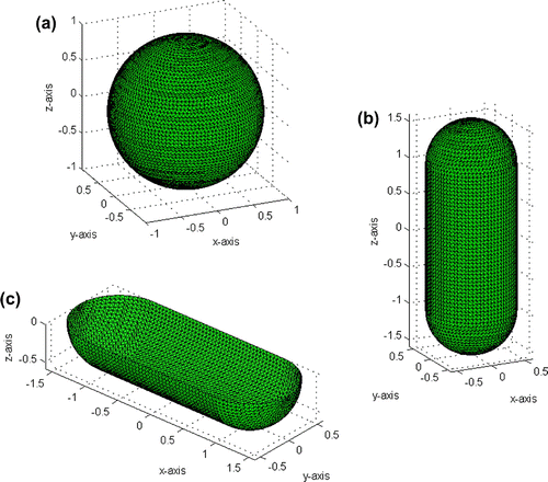
For the following numerical experiments we will choose to validate the proposed supersonic intensity methodology using smooth surfaces (that correspond to star-shaped domains) with different geometrical properties (see Figure ). In all numerical experiments, the measured pressure at a point is generated by the sum of the 10 monopoles distributed over a surface inside
. The analytical formula used to compute the field for each monopole is given by (Equation6
(6)
(6) ) or (Equation27
(27)
(27) ) for half-space conditions. The column vector
contains the exact generated pressure
in
added by the vector
with Gaussian entries and 40 dB signal-to-noise ratio (SNR) to simulate measurement errors, i.e.
3.3. Spherical geometry
Here, and
are spherical surfaces. The surfaces of
and
have, respectively, a radius of 1 and 1.05 m. The spherical surfaces are decomposed into 4990 points over 9976 triangles as shown in Figure (a). At
the maximum diameter between edges of the triangles is 5 cm and in
we keep an identical point distribution. Let the fluid sound speed be the speed of sound in air,
and density
. The 10 monopoles, used to generate the data, are distributed over a sphere of radius 0.9 m with
locations shown in Figure (a). Between the monopoles, the minimal arc-length distance over the
directions is 60 cm and over the
direction is 40 cm.
Over a spherical surface there is an explicit representation of the supersonic intensity based on spherical harmonic representation (see [Citation9]). In Figure we show the spherical supersonic intensity reconstruction and resultant power . Notice that the supersonic intensity can be understood in terms of the half wavelength resolution
. For 60 Hz, Figure (a) shows that the supersonic intensity resolution is 3.14 m. Similarly for 140Hz, Figure (b) shows that the supersonic resolution is 1.04 m. In Figure (c) the reconstruction for 240 Hz will have a resolution of 0.52 m. Finally Figure (d) shows the supersonic reconstruction for 500 Hz with a resolution of 31.4 cm which is smaller than the
arc-length separation between monopoles. In this case the supersonic intensity shows the separation
between the monopoles. Finally notice how close is the resultant power from the supersonic intensity as the exact power, even when the power from the supersonic intensity is a smoother version of the exact power.
The proposed numerical supersonic decomposition is based on the spectral decomposition of the power matrix in (Equation39
(39)
(39) ). The resultant basis is utilized to solve (Equation40
(40)
(40) ) for the coefficients
and finally we obtain the non-negative intensity in
from (Equation41
(41)
(41) ). This non-negative intensity is shown in Figure , and we observe that this intensity spatially matches the spherical supersonic intensity results in Figure . Moreover in Table we show the power
calculated from the exact numerically generated intensity
as in (Equation38
(38)
(38) ) and the power
that results from the proposed non-negative intensity
. The error in Table shows that the power from the proposed non-negative intensity matches the exact power.
Figure 4. View of the exact intensity over the spherical plane ,
. (a) Intensity at 60 Hz, (b) 140 Hz, (c) 240 Hz, and (d) 500 Hz.
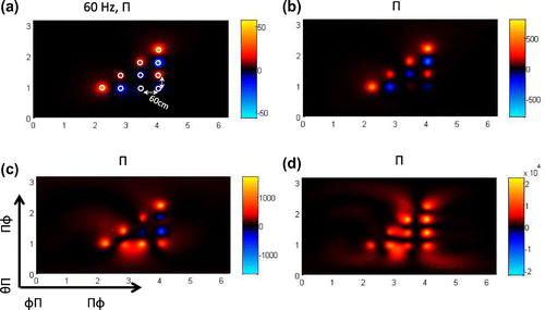
Figure 5. View of the spherical supersonic intensity over the spherical plane ,
. (a) Intensity at 60 Hz, (b) 140 Hz, (c) 240 Hz, and (d) 500 Hz.
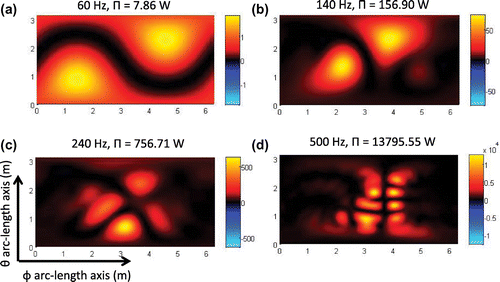
Figure 6. View of the calculated non-negative intensity using the power operator over the spherical plane ,
. (a) Intensity at 60 Hz, (b) 140 Hz, (c) 240 Hz and (d) 500 Hz.
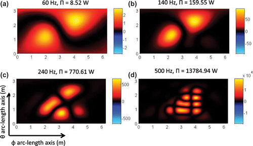
Table 1. Results from proposed supersonic intensity calculation over sphere.
3.4. Cylindrical geometry
Here, and
are cylindrical surfaces with endcaps (see Figure (b)).
have a radius of 0.5 m and a length of 1 m. The corresponding end-caps are closed by half spheres of radius 0.5 m. The surface
is decomposed into 2462 points over 4920 triangles as shown in Figure (b). At
the maximum diameter between edges of the triangles is 5 cm. The cylindrical measurement surface
have a radius of 0.55 m and the length is 1 m. The corresponding spherical end-caps have radius of 0.55 m. There are 2782 points distributed over
.
Figure 7. 3D View of exact intensity and the corresponding 2D view at 60 Hz.
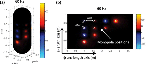
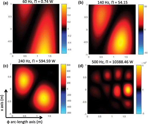
Figure 8. View of the calculated non-negative intensity using the power operator over the cylindrical surface. (a) Intensity at 60 Hz, (b) 140 Hz, (c) 240 Hz, and (d) 500 Hz.
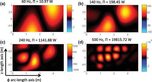
We utilize the proposed non-negative intensity technique as in the previous subsection and we plot the resultant intensity images in Figures and . Notice that Figure (a) shows the 2D planar image display of the three-dimensional surface image. Figure (b) shows the exact intensity
generated from 10 monopoles and the corresponding surface position of the monopoles. These monopoles are separated by 60 cm over the arc-length and 40 cm over the z axis. Figure shows the resultant supersonic intensity
over four frequencies: 60, 140, 240 and 500 Hz. Notice, as in the case of the spherical geometry, that the resolution of the proposed non-negative intensity image increases with frequency. The image in Figure (d) shows that the supersonic reconstruction for 500 Hz have a resolution of 31.4 cm which is smaller than the minimal arc-length separation for the arc-length separation of 60 cm. We expect higher frequencies to be able to separate all monopoles effectively. As in the previous subsection we include Table that compares the resultant power from non-negative intensity and the exact power. This table shows that the power from the non-negative intensity is close to the exact power.
Figure 9. 3D View of exact intensity and the corresponding 2D view at 500 Hz.
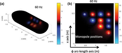
Table 2. Results from proposed non-negative intensity calculation over cylinder with spherical end-caps.
Table 3. Results from proposed supersonic intensity calculation over half-space cylinder.
3.5. Half-cylinder
Here, and
are half-cylindrical surfaces with spherical endcaps. The cylinders in
and
have, respectively, a radius of 1 m and 1.05 m and the length over x-axis is 2 m, where we consider only
.
is decomposed into 4990 points over 9780 triangles and
into 5392 points. At
the maximum diameter between edges of the triangles is 5cm. We utilize the proposed technique with the half-space power operator given in formula (Equation31
(31)
(31) ) and we plot the resultant intensity images in Figures and . Figure (a) shows the 2D image display over the three-dimensional surface
and in Figure (b) we show the exact intensity
generated from 10 monopoles and the corresponding surface position of the monopoles. These monopoles have a minimum separation of 60 cm over the z axis and 40 cm separation over polar arc-length. Figure shows the resultant non-negative intensity. Notice, as demonstrated in the previous experiments, that the resolution of the non-negative intensity image increases with frequency. As in the previous subsection we include Table that shows the resultant power from non-negative intensity and the exact power. This table shows that the resultant power from the non-negative intensity is close to the exact power.
Figure 10. View of the calculated non-negative intensity using the power operator over the half cylindrical plane. (a) Intensity at 60 Hz, (b) 140 Hz, (c) 240 Hz, and (d) 500 Hz.
4. Conclusion
Sections 2 and 3 extended the theory proposed in [Citation9]. We have shown explicit formulas of the kernel that corresponds to the power operator. These formulas are applied to discretize the power operator and obtain the eigenvalue decomposition that is used to approximate the non-negative intensity. The successful results for numerically generated data demonstrate that the proposed non-negative intensity approximates the supersonic intensity. Moreover, this non-negative intensity can be used to locate the radiation regions for arbitrary surfaces. There are promising results in Section 2 that can impact the numerical efficiency of the proposed numerical methodologies. Since the power operator is compact, the eigenvalues decay quickly to zero, and efficient Lanczos iterations can avoid the expensive calculation of the full eigenvalue decompositions for large matrix problems that result from complex vibrating structures.
Although it has not been the aim of this paper, there are still questions about the computation of the supersonic intensity for lower frequencies in which the acoustic half-wavelength is larger than the vibrator surface. When structural discontinuities are considerably smaller than the half-wavelength, bipolar intensity fields can occur and the constructed supersonic surface intensity is generally unable to locate the hot spots that radiate to the far-field. It has been proposed in previous papers [Citation8,Citation26] to include some subsonic information. Finally, it is also possible to utilize methodologies with index functions like [Citation27,Citation28], which have proven to resolve sources that are smaller than the acoustic wavelength.
Additional information
Funding
Notes
No potential conflict of interest was reported by the author.
References
- Williams EG. Supersonic acoustic intensity. J Acoust Soc Am. 1995 Jan;97(1):121–127.
- Williams EG. Supersonic acoustic intensity on planar sources. J Acoust Soc Am. 1998 Nov;104(5):2845–2850.
- Williams EG, Houston BH, Herdic PC, et al. Interior NAH in flight. J Acoust Soc Am. 2000;108:1451–1463.
- Magalhâes M, Tenenbaum R. Supersonic acoustic intensity for arbitrarily shaped sources. Acta Acust. 2006;92:189–201.
- Tenenbaum R, Magalhâes M. A new technique to identify arbitrarily shaped noise sources. Shock Vib. 2006;13:219–232.
- Correa C, Tenenbaum R. Useful intensity: a technique to identify radiating regions on arbitrarily shaped surfaces. J Sound Vib. 2013;332:1567–1584.
- Marburg S, L\"{o}sche E, Peters H, et al. Surface contributions to radiated sound power. J Acoust Soc Am. 2013 Jun;133(6):3700–3705.
- Williams EG. Convolution formulations for non-negative intensity. J Acoust Soc Am. 2013;134(2):1055–1066.
- Valdivia NP, Williams EG, Herdic PC. Equivalent sources method for supersonic intensity of arbitrarily shaped geometries. J Sound Vib. 2015;347:46–62.
- Colton D, Kress R. Inverse acoustic and electromagnetic scattering theory. 3rd ed. Vol. 93, Applied mathematical sciences. Berlin: Springer; 2013.
- DeLillo TK, Isakov V, Valdivia N, et al. The detection of the source of acoustical noise in two dimensions. SIAM J Appl Math. 2001;61(6):2104–2121.
- DeLillo TK, Isakov V, Valdivia N, et al. The detection of surface vibrations from interior acoustical pressure. Inverse Prob. 2003;19(3):507–524.
- Valdivia N. Uniqueness in inverse obstacle scattering with conductive boundary conditions. Appl Anal. 2004 Aug;83(8):825–851.
- Williams EG. Fourier acoustics: sound radiation and nearfield acoustical holography. London: Academic Press; 1999.
- Fahy F, Gardonio P. Sound and structural vibration: radiation, transmission and response. London: Elsevier/Academic; 2007.
- Isakov V, Wu SF. On theory and application of the helmholtz equation least squares method in inverse acoustics. Inverse Prob. 2002;18:1147–1159.
- Williams EG, Maynard JD. Holographic imaging without the wavelength resolution limit. Phys Rev Lett. 1980;45:554–557.
- Devaney AJ. Mathematical foundations of imaging, tomography and wavefield inversion.\pagination{\break} New York (NY): Cambridge University Press; 2012.
- Colton D, Kress R. Integral equation methods in scattering theory. New York (NY): Wiley-Interscience; 1983.
- McLean W. Strongly elliptic systems and boundary integral equations. New York (NY): Cambridge University Press; 2000.
- Stratton JA. Electromagnetic theory. IEEE Press Series on Electromagnetic Wave Theory.\pagination{\break} New Jersey (NJ): Wiley; 1941.
- Arfken G. Mathematical methods for physicists. 2nd ed. New York (NY): Academic Press; 1970.
- Valdivia N, Williams EG. Implicit methods of solution to integral formulations in boundary element methods based near-field acoustic holography. J Acoust Soc Am. 2004 Sep;116(3):1559–1572.
- Valdivia N, Williams EG. Krylov subspace iterative methods for boundary element method based near-field acoustic holography. J Acoust Soc Am. 2005 Feb;117(2):711–724.
- Valdivia NP. Numerical methods for near-field acoustic holography over arbitrarily shaped surfaces. In: Monroy FA, editor. Holography: different field of application. Rijeka, Croatia: InTech; 2011. p. 122–148.
- Fernandez-Grande E, Jacobsen F. Conservation of power of the supersonic acoustic intensity. J Acoust Soc Am. 2014;136(2):461–465.
- Li J, Liu H, Shang Z. Twoscatterers methods for locating multiple electromagnetic scatterers. SIAM J Appl Math. 2013;73(4):1721–1746.
- Li J, Liu H, Zou J. Locating multiple multiscale acoustic scatterers. Multiscale Model Simul. 2014;12(3):927–952.
Appendix 1
Bessel function estimates
For the following lemma we will use the notation .
Lemma 1.1:
For we have the relation
(A1)
(A1)
with the recurrence relations(A2)
(A2)
(A3)
(A3)
ProofSince and
is simple to get the formulas for
and
. Using the recurrence [Citation22, Chapter 11.7]
we get the relations in (EquationA1(A1)
(A1) ), (EquationA2
(A2)
(A2) ) for
. Similarly we can use the relation
to obtain the relation for in (EquationA1
(A1)
(A1) ), (EquationA3
(A3)
(A3) ).
Lemma 1.2:
For the remainders have the following behaviour
(A4)
(A4)
(A5)
(A5)
(A6)
(A6)
ProofThe formulas (EquationA4(A4)
(A4) ), (EquationA5
(A5)
(A5) ) follows using induction with the remainder recurrence relations in (EquationA2
(A2)
(A2) ), (EquationA3
(A3)
(A3) ), respectively. Then using formula (EquationA4
(A4)
(A4) ) in the relation
yields (EquationA6(A6)
(A6) ).