 ?Mathematical formulae have been encoded as MathML and are displayed in this HTML version using MathJax in order to improve their display. Uncheck the box to turn MathJax off. This feature requires Javascript. Click on a formula to zoom.
Abstract
In this paper, we present a novel class of iterative reconstruction methods for severely angular undersampled or/and limited-view tomographic problems with fan-beam scanning geometry. The proposed algorithms are based on a new analytical transform which generalizes Fourier-slice theorem to divergent-beam scanning geometries. Using a non-rigid coordinate transform, divergent rays can be reorganized into parallel ones. Therefore, one can employ a simpler parallel-beam projection model instead of more complicated divergent-beam geometries. Various existing iterative reconstruction techniques for divergent-beam geometries can be easily adapted to the proposed framework. The significant advantage of this formulation is the possibility of exploiting efficient Fourier-based recovery methods without rebinning of the projections. In case of highly sparse measurements (few-view data), rebinning methods are not suitable due to error-prone angular interpolation involved. In this work, three new methods based on the novel analytical framework for fan-beam geometry are presented: the Gerchberg-Papoulis algorithm, the Neumann decomposition method and its total variation regularized version. Presented numerical experiments demonstrate that the methods can be competitive in reconstructing from few-view noisy tomographic measurements.
1. Introduction
Direct reconstruction methods in X-ray computed tomography (CT) are proven to be fast and simple to implement [Citation1,Citation2]. They are based on a one-step approximation of a solution to inverse problem by backprojecting all measured tomographic projections. In order to overcome the blurring effect of the back-summation procedure, projections are convolved with a high-pass filter (e.g. a ramp filter). In practice, commonly used direct methods include Filtered Back Projection (FBP) algorithm for parallel and fan-beam geometries and Feldkamp–Davis–Kress (FDK) algorithm for the cone-beam geometry [Citation3]. The filtered backprojection procedure can be considered as a discrete approximation to inverse Radon transform formula which maps the space of measurements to the space of objects.
The FBP algorithm for parallel-beam geometry can also be introduced using Fourier-slice theorem (FST) [Citation1,Citation3,Citation4]. In two-dimensional (2D) case, FST states that the one-dimensional (1D) Fourier Transform (FT) of a single projection gives the corresponding orthogonal ’slice’ in 2D spectral domain. Therefore by taking 1D FT of an each subsequent projection, one can fill the 2D frequency spectrum with the corresponding Fourier coefficients in polar coordinates. In order to reconstruct an image, interpolation from polar to Cartesian coordinates (a regridding procedure) and the 2D inverse FT are required. When the measured projection space is sampled richly and in accordance with the Nyquist–Shannon theorem, the reconstruction with direct Fourier method tends to be similar to the convolution-backprojection approach. However, when the projection data are sparse and undersampled, the Fourier-based reconstruction can result in aliasing artefacts. Normally, the error originates from the regridding step which can lead to frequencies overlapping due to angular undersampled measurements. This phenomenon is inherent for higher frequencies, which are responsible for the edges in images. In practice, the convolution-based reconstruction methods are used due to straightforward implementation [Citation3,Citation4]. However, the Fourier-based reconstruction approaches are computationally efficient due to Fast Fourier Transform (FFT) [Citation3].
In general, however, all direct methods fail to reconstruct from noisy sparse measurements due to the ill-posed and ill-conditioned nature of the inverse problem [Citation5]. When the sampling rate is lower than it is required by the Nyquist–Shannon theorem (twice the frequency maximum present in data), a high level of noise and the loss of spatial resolution are expected in the reconstructed images. In clinical CT, a limited sampling rate is associated with the requirements to minimize the ionizing radiation dose. In material science, one would like to improve temporal resolution of dynamic (4D) experiments by performing faster acquisition with shorter exposures [Citation6].
Iterative Image Reconstruction (IIR) techniques are better adapted to deal with ill-posed inversion than direct methods as they can account for more accurate modelling of the acquisition process and allow the use of a priori information [Citation5]. Due to inaccurate and noisy measurements, IIR methods often require an additional regularity on the solution to ensure well posedness of inversion. For instance, the spatial regularization can be imposed through smoothness (Tikhonov -norm or Laplacian) [Citation5], gradient sparsity (Total Variation (TV) semi-norm) [Citation7], piecewise-smooth
[Citation8], various time-frequency-transformations [Citation8], patch-based priors [Citation6] and others.
The majority of IIR techniques are based on the projection-image space alternating error-correcting refinements where a priori information is applied in the image space only. The class of IIR methods based on the FT has an additional flexibility of embedding prior information in both spatial and frequency domains. Some examples of those methods are non-uniform FFT (NUFFT) [Citation9,Citation10], equally sloped tomography method [Citation11,Citation12], and Gerchberg-Papoulis (GP) algorithm [Citation2,Citation13–Citation17]. In this paper, we will focus on the GP method – a powerful and efficient FT-based IIR technique which is well suited for the reconstruction from sparse tomographic measurements. The GP method was initially introduced to solve 1D problem of out-of-band signal extrapolation [Citation18,Citation19]. Gerchberg proved convergence of the method in the absence of noise [Citation18] and the regularized version was proposed later in [Citation14]. The significant advantage of the GP algorithm over the main class of projection-image space IIR methods is the ability of suppressing noise and image artefacts by applying various constraints in both spectral and image domains. In the spatial domain, conventional regularization techniques can be used: non-negativity, smoothness, defined spatial support, bounded intensity values and others. In the spectral domain, frequency filtering, band-limiting (e.g. zeroing coefficients outside known frequency support), adaptive to sparse measurements k-space interpolation and other techniques can be applied. The use of the GP method for super-resolution problems [Citation20,Citation21] provides an insight to similar challenges in tomographic reconstruction, such as the limited data and missing wedge reconstruction [Citation8]. The GP method enables computationally efficient and high-quality reconstructions from few-view tomographic data. The disadvantage of the GP method is its inapplicability to divergent-beam measurements due to the limitations of the classical FST.
Previously, there were different attempts to generalize the classical FST to divergent-beam geometries [Citation22–Citation24]. These techniques were developed to avoid rebinning of divergent rays into parallel rays [Citation4]. The rebinning step can be expensive memory-wise for larger data-sets since it requires storing the result of interpolation. Notably, when only a few projections available and the reconstruction problem is severely angular undersampled, the rebinning step will result in significant errors due to interpolation. Therefore, the rebinning of projections should be avoided in this case.
In [Citation22], a novel approach to generalization of the FST was proposed which is different from the methods in [Citation23,Citation24]. The core of a method is in the simple non-rigid coordinate transform in image space which allows the further use of the classical FST for divergent-beam geometries [Citation22]. This formulation relaxes the difficulty which is associated with the use of the FST for divergent-beam geometries and therefore any FT-based IIR method can be implemented using the properties of the Generalized FST (GFST).
In this paper, along with the Fan-Beam GP (FBGP) method [Citation16], we present two new iterative algorithms which are also based on the GFST: Neumann Decomposition Shepp-Logan (NDSL) method and its TV-regularized version (NDSL-TV). The NDSL method was successfully used previously for the parallel-beam geometry [Citation25,Citation26] and it is based on the decomposition of inverse projection operator into the Neumann series of approximate operators [Citation27,Citation28]. Here we reformulated the NDSL method to fan-beam geometry using the GFST and presented the TV-regularized version of the method (NDSL-TV). To make our presentation more self-consistent, we introduce the GFST in Section 2.1. The FBGP method is presented in Section 2.2 and details to improve its performance given in Section 2.3. The NDSL and NDSL-TV methods are presented in Section 2.4. The numerical experiments for comparison of the FBGP, NDSL and NDSL-TV methods are given in Section 3. Discussion is given in Section 4 and conclusions are given in Section 5.
2. Theory
2.1. The GFST
Here we introduce the GFST [Citation22] in application to fan-beam geometry with a flat detector; however, the theorem can be extended to other divergent-beam geometries (e.g. the cone-beam geometry). The core of the GFST lies in a non-linear coordinate transform which helps to translate the fan-beam problem into the parallel-beam one. For each angular scanning position, the object undergoes a unique forward coordinate deformation where divergent rays become parallel and therefore the classical FST can be used directly. In order to return to the original coordinate system, the inverse deformation must be applied.
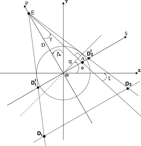
Here we consider the standard acquisition scheme for the 2D fan-beam geometry in CT (see Figure ). Let the domain of unknown function g(x, y) is bounded by the unit circle , where fan-beam source E rotates along the circular path and (x, y) is the coordinate system rotated by the angle
, such as
where is a distance from E to the origin of the rotated coordinate system (s, p). The detectors are located on the straight line
. For the fixed angle
, each ray EA inside the fan-beam can be characterized by its angle
from the central ray, and its distance q from O. The angle between the x-axis and the beam is denoted by
, while
denotes an angle between the x-axis and the line perpendicular to the beam. The measured signals on the detectors line
can also be considered on the line of virtual detectors
.
We propose the following projective (’deforming’) non-linear transformation of the point (s, p) in the rotated coordinate system:(1)
(1)
The transform (Equation1(1)
(1) ) changes rays in the fan-beam in (x, y) coordinate system into straight lines parallel to the v-axis. Therefore, for the corresponding angle
, the initial image g(x, y) will be deformed into a new image g(X(u, v), Y(u, v)):
(2)
(2)
The inverse substitution in (Equation2(2)
(2) ):
, where
are polar coordinates of (x, y) and
are the coordinates of a fan-beam passing through this point. Notably, the measured signal becomes zero if
. Then fan-beam projection can be expressed as follows:
(3)
(3)
The transition from the coordinates (x, y) to (u, v) is carried out with the help of the Jacobian matrix J, which is defined using (Equation2(2)
(2) ) as:
(4)
(4)
Finally, the Equation (Equation3(3)
(3) ) in a new system of coordinates can be written as:
(5)
(5)
In the derivation of Equation (Equation5(5)
(5) ), we used the formulae:
(6)
(6)
where . From the geometrical formulation of the problem (see Figure )
, which implies that
(notice that in fan-beam geometry
,
). As a result, the Jacobian module
can be cancelled with the multiplier
and removed from the delta-function.
Furthermore, we rename the integrand g(u, v) in the integral (Equation5(5)
(5) ) into
and define a new function
. Here the index
appears since the (u, v) coordinates depend on the angle
. The FT of the function
leads to the generalized formulation of the FST for fan-beam geometry [Citation22]:
(7)
(7)
Thus, the GFST is now expressed in (u, v) coordinates which are obtained from the initial coordinates (s, p) by the non-linear projective variable transformation (Equation1(1)
(1) ). This is a one-to-one transform between the domain of the unknown function g(x, y) and the deformed function
. Hence, the FT of the deformed fan-beam projection (multiplied by the cosine of the incidence angle of each ray in the fan-beam) coincides with the central section of the 2D Fourier-image of the deformed object
.
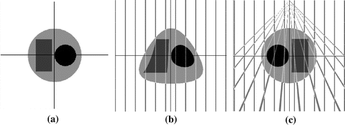
In Figure , we illustrate the deformation procedure (Equation1(1)
(1) ) applied to a simple 2D phantom which consists of two circles and a rectangle. Spatial transformation from (s, p) coordinates into the deformed (u, v) coordinates is performed using bilinear interpolation. In Figure (b), direct deformation of the phantom (a) is given and (c) shows the inverse deformation of (b). Notably, when the inverse transform is applied to the deformed image (b) the object returns to its initial geometrical shape (c). In Figure (c), one can see that the parallel rays in the deformed space (b) have become fan-rays in the original coordinate system. Therefore, one can scan an object using fan-beam geometry and after transformation (Equation1
(1)
(1) ) the resulting deformed object (b) is suitable for parallel-beam geometry. Furthermore, in image (c) one can notice that parallel and fan-rays cross each other exactly at the same points along the x-axis, which proves that the deformation has been applied correctly. Therefore in the deformed space, the classical FST can be applied directly.
Figure 3. (a) original image of Lena (cropped in a circle shape), ; (b) deformed image,
; (c) inverse deformation of (b). The minor isotropic blurring effect of two bilinear interpolations (forward-backward deformation steps) is noticeable in (c).

For the sake of interesting morphing effects of non-linear deformation (Equation1(1)
(1) ), we repeat the experiment with an image of Lena (see Figure ). Although image (c) looks similar to the original image (a), it has been deformed twice by means of bilinear interpolation and it is actually a smoothed version of (a). The repetitive (forward-backward) interpolation steps of GFST-based IIR algorithm can result in over-smoothing of the solution. More accurate interpolation approaches can lead to better results, therefore in our experiments we use bicubic interpolation [Citation29]. In our implementation, we use Matlab function interp2 with ’cubic’ parameter [Citation30].
2.2. Gerchberg-Papoulis algorithm for fan-beam geometry
The classical iterative GP method for parallel-beam scanning geometry is based on the application of the FST and it is presented in Algorithm 1 [Citation2,Citation13–Citation17]. In Algorithm 1, and
are the operators of direct and inverse 2D Fourier-transform, respectively.
The operators
and
are responsible for applying a priori information (every n-th iteration) in spatial and frequency domains, respectively (see Table ). Additionally, the operator
maps Fourier spectrum of projections on the radial lines to the 2D Cartesian Fourier space. The regridding procedure is an important part of the GP algorithm for reconstruction from undersampled projection data and it requires a special care to avoid interpolation errors [Citation16] (see also Section 2.3). Before giving more technical details on operators
, we introduce the GP method for fan-beam geometry (FBGP) [Citation16].
Table 1. The list of actions inside the operators and
.
Let us define a deformation matrix T as:(8)
(8)
Using matrix T, one can transform the coordinate system (s, p) into a new coordinate system (u, v): . The rotation of the coordinate system (x, y) by
(see Figure ) is defined by the following rotation matrix:
(9)
(9)
Then the space of the deformed object can be represented using new coordinates as:
(10)
(10)
where is the inverse of
. Note that one can rotate an object first and then deform it (two interpolations involved) or the deformation can be performed directly from the current source position (one interpolation).
To reduce computational cost and minimize interpolation errors, we use the later case with bicubic interpolation instead of bilinear. Therefore, only two 2D interpolations are needed for forward and inverse deformations (Equation10
(10)
(10) ). Apart from the forward-inverse deformations for angle
, the FBGP method (see Algorithm 2) is exactly the same as the classical GP method (see Algorithm 1).
2.3. Some important aspects of the GP and the FBGP algorithms
The 1D FT can be applied to a measured projection which results in a set of discrete points lying along the radial line in the frequency domain.
Figure 4. (a) The set of radial lines for four projections in polar coordinates with Cartesian coordinate system superimposed. The symmetric strip of width is centred on each radial line determining the trust region where interpolation is performed. All frequency coefficients outside the strip are considered unreliable and therefore ignored during the interpolation (zeroed before the first 2D IFT). The strip interpolation is proven to be much more accurate than the classical isotropic interpolation methods for undersampled projection datasets; (b) Zoomed strip region shows two 1D interpolations employed within the strip to regrid radial data points to Cartesian grid.
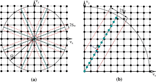
Therefore, for every projection angle, the spectral domain is filled with data-contained radial lines (see Figure (a)). In order to apply the 2D inverse FT (IFT) to , it is necessary to interpolate values lying on the radial lines in polar coordinate system to Cartesian coordinate system
. Traditional spatially invariant regridding techniques are extremely sensitive to outliers [Citation3,Citation10,Citation11]. In the case of limited projections, the spectral domain is sampled non-uniformly with bigger gaps (the missing wedges) further from the centre of coordinates (see Figure (a)). However, due to noise present in the data, the missing wedges contain some frequencies which lead to image artefacts after application of the 2D IFT. Therefore, one should consider applying interpolation within some trust region only where data are more reliable. To increase accuracy, we employ a strip interpolation method [Citation16] which is proven to be successful to recover images with less artefacts when the data spectrum is sparse.
In our implementation, we choose a symmetrical strip with defined width , which is centred on each radial line in polar coordinate system (see Figure ). Inside the strip, two 1D interpolations are performed, the nearest neighbour interpolation across the strip and linear interpolation along the strip (see Figure (b)). All data points within the strip are considered to have equal weights; however, additional weighting factors can be assigned to more distant from the central radial line data points.
To further improve the accuracy of the strip interpolation, the width of a strip continuously shrinks in iterations with a period and some multiplier
. At each n-iteration, the condition
is checked and if fulfilled the width of a strip is updated as
. Therefore if
we update the strip every iteration. The initial width
and the multiplier
are important parameters which can affect the convergence of the GP algorithm. The choice of
is usually an empirical one and also can depend on the sampling rate. The main idea of the iterative change of the width is in the ability of the algorithm to adapt to newer estimates by improving the accuracy of interpolation (this is equivalent to the refinement of the trust region based on new data). Normally, a wide strip leads to a slower convergence and too narrow strip can result in large reconstruction errors (or even divergence of the algorithm). Previously, it was established [Citation16] that it is important to iteratively reduce the strip’s width in iterations until a small width value is reached. Alternatively, if the width of a strip is kept constant in iterations, then the algorithm can stagnate on earlier iterations and even diverge.
Apart from the non-standard interpolation procedure (included into operator , see Table ), there are additional elements which can help to obtain better reconstruction and accelerate convergence of the GP method. For instance, the measured spectrum can be bounded using the Nyquist theorem in order to remove some spectral coefficients, e.g. to zero frequencies above the Nyquist frequency. It is also important to regularize reconstruction and it can be done conveniently in the Fourier domain [Citation14]. High frequencies can be suppressed in accordance with the level of noise in projections:
(11)
(11)
where is a regularization parameter and
. The regularization parameter can be found empirically or using a discrepancy principle [Citation31]. In the image domain (operator
), one can apply positivity and bounded support constraints. Notably one can also regularize in image space, however we do not implement this in our modification of the GP algorithm.
In order to quantify reconstructed images, we use the following relative error:(12)
(12)
where g is a reconstructed image and is an exact phantom.
2.4. Iterative method of Neumann decomposition with Shepp-Logan filter for fan-beam geometry
In this section, we present a different reconstruction approach which is also based on the proposed deformation (Equation8(8)
(8) ).
The tomographic reconstruction problem can be formulated as a solution to the system of linear algebraic equations [Citation1–Citation5]:(13)
(13)
where is a vectorized representation of unknown object (N is the total number of image elements),
is a vectorized sinogram,
is a noise component present in data and
is a sparse system projection matrix which maps the ’space of objects’ into the ’space of observations’. The formal solution to the problem (Equation13
(13)
(13) ) can be written as
, where
is the inverse or pseudo-inverse of
. However, since
is strongly ill-conditioned for undersampled data the direct inversion is not feasible and also not unique in presence of noise
[Citation5]. The approximate solution can be found through the Moore–Penrose pseudo-inversion or iteratively using the Least-Squares (LS) criterion where the
-norm is minimized by residual
. Alternatively, one can decompose
matrix into a Neumann series [Citation27] and arrive at the iterative scheme which can be adapted to solve the reconstruction problem (Equation13
(13)
(13) ) [Citation25,Citation26,Citation28,Citation32].
The projection matrix can be decomposed as
, where
is some known approximation to the unknown operator
. Using the Neumann series decomposition [Citation27] one can re-write operator
as
(14)
(14)
where is the identity matrix and
is a positive relaxation parameter. Convergence of the series (Equation14
(14)
(14) ) is ensured by
.
For tomographic reconstruction problem, we can re-write (Equation14(14)
(14) ) as [Citation25,Citation28]:
(15)
(15)
where is a discrepancy vector and
is replaced with the known approximation of the continuous inverse Radon transform
given as [Citation1]:
(16)
(16)
where ,
or
(see Figure ), and
is a Shepp-Logan (SL) filter:
(17)
(17)
where is a step on p and Q is defined by formula (Equation8
(8)
(8) ). Note that the element to deal with fan-beam projections using the GFST is embedded into Q operator in (Equation16
(16)
(16) ).
The classical FBP algorithm with the SL filter in the inner integral is expressed in (Equation16(16)
(16) ) and iterative method (Equation15
(15)
(15) ) is defined as Neumann Decomposition Shepp-Logan (NDSL) algorithm. Notably, the NDSL method shares similarities with the Landweber reconstruction method [Citation5], which is a well-known iterative technique to solve the LS problems. The main difference between the two methods is the nature of the operator
(Equation15
(15)
(15) ). The Landweber algorithm uses
, where
is a backprojection (adjoint) operator without filtering. However, one can consider the NDSL algorithm (Equation15
(15)
(15) ) as an accelerated version of the Landweber method [Citation33], when high-pass filtering of the sinogram’s residual is performed before the backprojection.
Additionally, to ensure stable convergence of the NDSL method (Equation15(15)
(15) ) we regularize it using the TV penalty [Citation7]. The reconstruction-regularization alternating process is based on the operator splitting method [Citation12,Citation13] and summarized in Algorithm 3. The TV minimization problem in Algorithm 3 is solved using explicit Rudin–Osher–Fatemi (ROF) scheme [Citation7] with a small time step parameter to ensure convergence. In this experiment, the regularization parameter
has been found empirically by minimizing
error. For real data case, one can use Morozov’s principle instead [Citation31].
The deformation procedure (see Section 2.1) is included in the forward (fan-beam geometry) model (on every n-iteration, the object
is deformed). The scheme (Equation15
(15)
(15) ) converges fast and also robust to noisy and undersampled data due to added TV term.
3. Numerical results
In this section, we present preliminary numerical results for three iterative GFST-based algorithms for fan-beam geometry (see Section 2.1). The compared algorithms include: FBGP (see Section 2.2), NDSL, NDSL-TV (see Section 2.4) and the classical Simultaneous Iterative Reconstruction Technique (SIRT) [Citation1] for fan-beam geometry. Notably, in SIRT we do not use any of the proposed deformation principles. The reconstruction error (Equation12
(12)
(12) ) is used to quantify the results.
3.1. Synthetic models and algorithms initialization
In order to test our algorithms accurately, we used two analytical phantoms with different properties. Model 1 is a smooth phantom and consists of six symmetric Gaussians (see Figure (a–b)). Model 2 is a piecewise-constant phantom and consists of six symmetric circles with uniform intensity (see Figure (c–d)). The compared algorithms can demonstrate a different behaviour to these models.
Figure 5. Synthetic phantoms used in numerical experiments: (a) model 1 (six symmetric Gaussians); (b) surface representation of model 1; (c) model 2 (six symmetric circles); (d) surface representation of model 2. The corresponding projection data is obtained analytically using the fan-beam geometry in Figure .

Figure 6. Various initializations of for iterative algorithms. Reconstructions of model 2 from 11 projections (
) with noise level
; (a) backprojection; (b) FBP; (c) The Baranov’s approximation [Citation34].
![Figure 6. Various initializations of g(0)(x,y) for iterative algorithms. Reconstructions of model 2 from 11 projections (K=11) with noise level κ=3%; (a) backprojection; (b) FBP; (c) The Baranov’s approximation [Citation34].](/cms/asset/4c1eb35e-9309-445a-a2dc-21e2ca5c2702/gipe_a_1340946_f0006_oc.gif)
It is also important to establish a good initialization (the first approximation to the seeking solution) for the proposed IIR schemes (see Algorithms Equation1(1)
(1) –Equation3
(3)
(3) ). Potentially, if the first approximation to the solution is well chosen, it can have a positive impact on the speed of convergence and the final error. Here we compare four different initializations for our algorithms: zero image
, backprojected image (see Figure (a)), SL filtered backprojected (FBP) image (see Figure (b)), and initialization using the Baranov’s criteria of minimal projections [Citation34] (see Figure (c)). The reconstructions in Figure are performed using only 11 fan-beam projections (K) in
angular range in radians with
of randomly distributed noise (
) added to the projections.
Our experiments have shown that the initial approximation for using the Baranov’s criteria [Citation34] (see Figure (c)) produces the best results (convergence is faster and the final error is lower) for all compared algorithms. Therefore, we will use this initialization in our experiments.
3.2. Numerical comparisons
We start our numerical simulations with a thorough search for all parameters to each compared algorithm. For the FBGP algorithm, the following parameters have been empirically established: the width of the strip , the multiplier
and the frequency of the width updates
(see Section 2.3). For the NDSL and NDSL-TV algorithms, the most important parameters are the step size
which controls the convergence of iterations and the regularization parameter
for the TV minimization in Algorithm 3. To find
, we performed several full reconstructions with different values of
(see Figure ). Notably, the parameter
has been found prior to this experiment and kept fixed to establish
for the NDSL-TV method. We established that the optimal parameters
and
give the best results for the NDSL and NDSL-TV methods, respectively (see Figure ). For the SIRT method, we use 150 iterations which is sufficient for the method to converge.
Figure 7. Optimization procedure to find the optimal step parameter for the NDSL (left) and NDSL-TV (right) methods. Model 1,
,
.
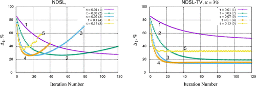
Once all parameters have been identified through empirical optimization procedure for each algorithm, we proceed with numerical comparisons of methods with respect to various levels of noise () and the number of projections (
) in
angular range in radians. We apply reconstruction methods to both models 1 and 2. In Figure , we demonstrate the best achieved reconstruction errors
for
and in Figure for
.
One can see that the NDSL-TV algorithm outperforms the unregularized NDSL method, FBGP and the SIRT methods. The NDSL-TV reconstruction results in the smallest errors for the limited data conditions . In the case when more projections available (
), the efficiency of the NDSL-TV and the FBGP algorithms reduces (no significant enhancement achieved), while the NDSL algorithm has almost linear correlation of errors with respect to the number of projections.
Figure 8. Reconstructions of model 1 (left) and model 2 (right) using different number of projections () and the same level of noise
. The NDSL-TV method outperforms (in terms of
) all other algorithms significantly.
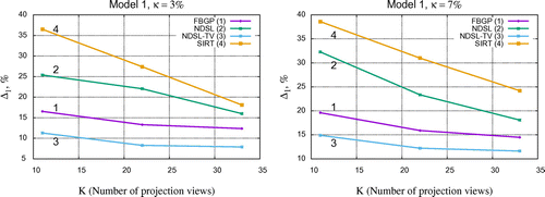
Figure 9. Reconstructions of the model 1 (left) and model 2 (right) using the different number of projections () and the same level of noise
. The NDSL-TV method outperforms (in terms of
) all other algorithms.
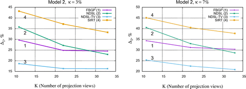
Figure 10. Reconstructions of model 1 (left) and model 2 (right) with respect to the iteration number and error. For both models the NDSL-TV method gives stable convergence to the point of stagnation.
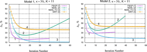
To demonstrate the rate of convergence for the compared algorithms, we show the curves of residual errors with respect to the iteration number for both models (see Figure ). One can see that the NDSL method is not stable and diverges quickly after ten iterations. The NDSL-TV method reaches the lowest error and ensures stable convergence to the point of stagnation (we iterated up to 150 iterations). The FBGP method is the quickest in convergence during first iterations; however, it slowly diverges afterwards and the minimal error is still higher than for the NDSL-TV method. The highest error is obtained with SIRT for both models. Notably we used the SIRT algorithm in its classical form with zeroed image as an initialization. Additionally, no a priori information is integrated into the algorithm compare to other methods. Consequently, it is expected that errors can be higher for SIRT.
In Figures and , we demonstrate the reconstructed images for models 1 and 2, respectively. The reconstructions are linked to the curves presented in Figure , the images shown for the lowest errors achieved.
Figure 11. Reconstruction of the smooth model 1, ,
using the methods: (a) SIRT,
; (b) FBGP,
; (c) NDSL,
; (d) NDSL-TV,
. Note the flatten centres (peaks) of the reconstructed Gaussians with the NDSL-TV method.
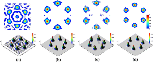
Figure 12. Reconstruction of the discontinuous model 2, ,
using the methods: (a) SIRT,
; (b) FBGP,
; (c) NDSL,
; (d) NDSL-TV,
. Note the smooth shapes of the reconstructed circles with the FBGP method.
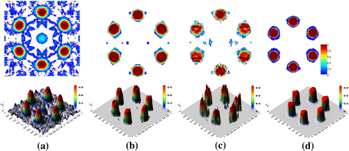
Since the compared methods are intrinsically different (especially the FBGP and the NDSL methods) they own different reconstruction characteristics and therefore the reconstructed images are dissimilar (see Figures and ). The smooth model 1 is reconstructed quite well with the FBGP and the NDSL-TV methods (see Figure ). Notably, the NDSL-TV algorithm flattens the centres of Gaussians. This is mainly due to the piecewise-constant edge preserving properties of the TV penalty. Although, the total reconstruction error is higher with the FBGP method than with the NDSL-TV method the centres of Gaussians are recovered better with the FBGP method. SIRT reconstruction is full of aliasing artefacts; however, the shapes of Gaussians are preserved. The discontinuous model 2, however is reconstructed very poorly with the SIRT algorithm, image contains many artefacts and the uniform shapes of circles are distorted (oversmoothed). It is known that SIRT can implicitly smooth an image in iterations. The model is reconstructed much better with the NDSL-TV method due to piecewise-constant nature of the phantom itself (see Figure ). The FBGP method fails to reconstruct the uniform structures of circles and smooths the boundaries (a bit similar to SIRT reconstruction, but not so extreme). The unregularized NDSL method, as expected, results in a very noisy reconstruction for both models.
4. Discussion
Although the performance of the FBGP algorithm has not been superior among the algorithms presented here, it can be further improved. The strip interpolation is one of the most important elements of the FBGP algorithm that affects its performance. Overall, the FBGP method remains a powerful and computationally efficient technique for reconstruction of the undersampled data. Arguably, the repetitive use of interpolation (even of higher orders) in the deformation procedure can affect the quality of the reconstructed images. In order to decide which interpolation is more suitable for the task and check if the error accumulates in iterations, one needs to initiate a thorough investigation of the issue. We will consider this in our future work. On this stage of research, the proposed framework can be used for fast prototyping and testing various IIR techniques (including the Fourier-based ones) for divergent-beam geometries.
5. Conclusion
In this work, we presented a novel class of iterative solutions for fan-beam geometry based on the generalized Fourier Slice Theorem. The proposed approach helps to generalize parallel-beam specific state-of-the-art reconstruction techniques to divergent-beam geometries. We have shown that the Fourier-based iterative methods, such as the Gerchberg-Papoulis algorithm can be adapted to reconstruct divergent-beam data using the proposed framework. This approach avoids rebinning step which can be undesirable for few-view tomography. The simple implementation of the generalized projection slice theorem makes it ideal for prototyping various iterative algorithms. The acceleration using the Fast Fourier Transform routines makes this approach more feasible than the classical iterative methods for reconstruction of big datasets.
Our preliminary numerical experiments have shown the potential in applicability of the generalized slice theorem to severely angularly undersampled reconstruction problems in X-ray tomography. Three new iterative methods for fan-beam scanning geometry have been introduced. Methods have been compared with each other and also with the classical algebraic fan-beam algorithm. The TV-regularized Neumann decomposition method has demonstrated the best performance among compared methods. Our future work will include improving these methods, applying to reconstruction of real data and generalization to cone-beam case.
Additional information
Funding
Notes
No potential conflict of interest was reported by the authors.
References
- Kak AC, Slaney M. Principles of computerized tomographic imaging. New York (NY): IEEE Press; 2009.
- Bertero M, Boccacci P. Introduction to inverse problems in imaging. Boca Raton: CRC Press; 1998.
- Buzug TM. Computed tomography: from photon statistics to modern cone-beam CT. Berlin: Springer; 2008.
- Herman GT. Fundamentals of computerized tomography: image reconstruction from projections. London: Springer; 2009.
- Vogel CR. Computational methods for inverse problems. Philadelphia: SIAM; 2002.
- Kazantsev D, Van Eyndhoven G, Lionheart WRB, et al. Employing temporal self-similarity across the entire time domain in computed tomography reconstruction. Philos Trans Roy Soc London A. 2015;373(2043):20140389
- Rudin L, Osher S, Fatemi E. Nonlinear total variation based noise removal algorithms. Physica D. 1992;60(1–4):259–268.
- Kazantsev D, Ovtchinnikov E, Withers PJ, et al. Sparsity seeking total generalized variation for undersampled tomographic reconstruction. Proceedings of 13th International Symposium on Biomedical Imaging (ISBI IEEE); Prague; 2016. p. 731–734.
- Matej S, Fessler JA, Kazantsev IG. Iterative tomographic image reconstruction using Fourier-based forward and back-projectors. IEEE Trans Med Imaging. 2004;23(4):401–412.
- O’Connor YZ, Fessler J. Fourier-based forward and back-projectors in iterative fan-beam tomographic image reconstruction. IEEE Trans Med Imaging. 2006;25(5):582–589.
- Fahimian BP, Yu M, Cloetens P, Jianwei M. Low-dose X-ray phase-contrast and absorption CT using equally sloped tomography. Phys Med Biol. 2010;55(18):5383–5400.
- Mao Y, Fahimian BP, Osher SJ, Miao J. Development and optimization of regularized tomographic reconstruction algorithms utilizing equally-sloped tomography. IEEE Trans Image Process. 2010;19(5):1259–1268.
- Lim J, Lee K, Jin KH, et al. Comparative study of iterative reconstruction algorithms for missing cone problems in optical diffraction tomography. Opt Express. 2015;23(13):16933–16948.
- Sato T, Norton SJ, Linzer M, Ikeda O, Hirama M. Tomographic image reconstruction from limited projections using iterative revisions in image and transform spaces. Appl Opt. 1981;20(3):395–399.
- Fienup JR. Iterative method applied to image reconstruction and to computer-generated holograms. Opt Eng. 1980;19(3):297–305.
- Pickalov V, Kazantsev D. Iterative Gerchberg-Papoulis algorithm for fan-beam tomography. Proceedings of 8th IEEE Region International Conference on Biomedical Engineering and Computational Technologies, SIBIRCON; Novosibirsk; 2008. p. 218–222.
- Defrise M, De Mol C. A regularized iterative algorithm for limited-angle inverse Radon transform. J Mod Opt. 1983;30(4):403–408.
- Gerchberg RW. Super-resolution through error energy reduction. J Mod Opt. 1974;21(9):709–720.
- Papoulis A. A new algorithm in spectral analysis and band-limited extrapolation. IEEE Trans Circuits Syst. 1975;22(9):735–742.
- Chatterjee P, Mukherjee S, Chaudhuri S, Seetharaman G. Application of Papoulis-Gerchberg method in image super-resolution and inpainting. Comput J. 2009;52(1):80–89.
- Salari E, Bao G. Super-resolution using an enhanced Papoulis-Gerchberg algorithm. Image Process, IET. 2012;6(7):959–965.
- Pickalov V, Kazantzev D, Ayupova NB, et al.. Considerations on iterative algorithms for fan-beam tomography scheme. Proceedings of 4-th World Congress on Industrial Process Tomography. Vol. 2. Aizu, Japan; 2005. p. 687–690.
- Chen GH. Shuai Leng S, Mistretta CA. A novel extension of the parallel-beam projection-slice theorem to divergent fan-beam and cone-beam projections. Med Phys. 2005;32(3):654–665.
- Zhao S, Yang K. Fan beam image reconstruction with generalized Fourier slice theorem. J X-ray Sci Technol. 2014;22(4):415–436.
- Likhachev AV, Pikalov VV. Three-dimensional emission tomography of optically thick plasma for the known absorption. Opt Spectrosc. 2000;88(5):667–675.
- Pikalov VV, Chugunova NV. Wide-aperture tomography of emissive objects. Opt Spectrosc. 2000;88(2):286–90.
- Stewart GW. Matrix algorithms: basic decompositions. Philadelphia (PA): SIAM; 1998.
- Press WH. Discrete Radon transform has an exact, fast inverse and generalizes to operations other than sums along lines. Proc Nat Acad Sci. 2006;103(51):19249–19254.
- Keys R. Cubic convolution interpolation for digital image processing. IEEE Transactions on Acoustics, Speech, and Signal Processing. 1981;29(6):1153–1160.
- MATLAB and statistics toolbox release 2012b. Natick (MA): The MathWorks Inc.
- Morozov VA. Methods for solving incorrectly posed problems. New York (NY): Springer; 1984.
- Wagner JM, Noo F, Clackdoyle R. 3-D image reconstruction from exponential X-ray projections using Neumann series. Proceedings of Acoustics, Speech, and Signal Processing (ICASSP 01). Vol. 3; Salt Lake City; 2001. p. 2017–2020.
- Paleo P, Mirone A. Ring artifacts correction in compressed sensing tomographic reconstruction. J Synchrotron Radiat. 2015;22(5):1268–1278.
- Baranov VA. A variational approach to non-linear backprojection. Proceedings of 4th International Symposium on Computerized Tomography. Novosibirsk, Russia; 1995. p. 82–97.

