 ?Mathematical formulae have been encoded as MathML and are displayed in this HTML version using MathJax in order to improve their display. Uncheck the box to turn MathJax off. This feature requires Javascript. Click on a formula to zoom.
Abstract
Image reconstruction in electrical impedance tomography (EIT) deals with an ill-posed and non-linear inverse problem. It has the objective of minimizing the difference between simulated (virtual) object data and electric voltage measurements performed on a non-simulated (real) object. In this paper, a new approach to the simulated annealing method applied to the reconstruction of EIT images is described. The main advantage of this approach is that all conductivity parameters are updated simultaneously. Most methods that employ simulated annealing to the problem of EIT usually evaluate each conductivity parameter individually resulting in high computational cost. The algorithm was tested both with computationally generated data and with measurements performed on a physical tank. In both cases, the method was able to make data inversion, determining the position, the dimensions and the conductivity of materials in an opaque object plane.
1. Introduction
The electrical impedance tomography (EIT) is a non-invasive imaging technique, in which certain electrical quantities are measured on an object surface in order to visualize the object interior. For 2D EIT reconstructions, the images are obtained through electrical properties such as conductivity and permittivity measured in various points on a plane within the object.
Conductivity distribution inside an object may be accessed through static and dynamic mathematical models. Static methods are used when the object electrical properties do not vary significantly during the time required for data collection. Otherwise, when rapid changes in the electrical properties occur, dynamic effects must be taken into account and a dynamic method must be used. Apart from dynamic and static categorization, EIT reconstruction methods can also be classified into difference methods and absolute methods. In a difference method, two electrical potential data-sets are measured corresponding to two different conductivity distributions. Based on the difference between these measurements, the difference on conductivity distributions can be estimated. In an absolute imaging method, an estimate is based on a single data-set of electrical potential measurements and the aim is to estimate the absolute conductivity distribution [Citation1].
The algorithm using an absolute method should solve a problem which is ill-posed, inverse, and shows great sensitivity to experimental noise and numerical errors [Citation2]. To perform the numerical data inversion, usually two problems must be solved, e.g. the forward and the inverse ones. In the forward problem, a differential equation solution is approximated by numerical methods, such as the finite difference method (FDM) [Citation3]. The inverse problem is solved using forward problem solution and measurement of potential on the object surface. Fundamentally, the inverse problem solution is achieved for the conductivity distribution that minimizes the difference between measured potentials and calculated potentials by the forward problem.
Apart from an efficient forward methodology, the solution of ill-posed inverse EIT problem requires a competent regularization/optimization method [Citation4]. Various numerical optimization methods have been applied to the EIT inverse problem solution, mainly local and global methods. Eppler and Harbrecht [Citation5] and Wang [Citation6] offer inverse problem solution examples by local methods. For some sort of global optimization methods, the most common ones in the literature are genetic algorithms [Citation7] and simulated annealing method (SA) [Citation1,Citation8].
The SA is an iterative stochastic optimization method that is able to escape from a local objective function minimum by employing the Metropolis criterion [Citation1,Citation9,Citation10]. The choice of the cooling rate and the new candidate solution are the most important decisions in a SA algorithm [Citation11].
The SA have been applied to a multitude of inverse problems: on problems of heat conduction with variable coefficients [Citation12], on problems of multiple combination of parameters [Citation13], for object recognition in noisy images [Citation14], in the synthesis of reversible circuits [Citation15].
The SA was originally proposed in the area of combinatorial optimization, that is, when the cost function is defined in a discrete domain [Citation9]. Corana et al. [Citation10] proposed some modifications to SA algorithm, in order to apply it to the optimization of functions defined in a continuous domain. Herrera et al. [Citation1] showed that SA could produce highly accurate solutions to EIT inverse problems using Corana’s method. However, the computational cost is high because each conductivity parameter is modified individually. For every update in the conductivity distribution, it is necessary to solve the forward problem [Citation8].
De Castro Martins et al. [Citation8] tested another neighbourhood heuristics approach solution. In that approach, the crystallization heuristic is used. This restrictive heuristic is more efficient in solving EIT inverse problem than the methodology used by Herrera et al. [Citation1].
In the present work, the EIT inverse problem was formulated as a minimization problem. This problem uses an objective function as a fitting criterion. The objective function is defined as the square of the difference between the measured values and those computed by a numerical model (least square criterion). In order to satisfy fitting criterion, it is used an algorithm based on simulated annealing combined with smoothing by Gaussian filter.
The proposed SA approach reduces the time needed to find the minimum of the objective function, because all conductivity parameters can be updated at the same time (Multi-element SA approach). Furthermore, the solutions produced by the proposed approach are as precise as the ones produced by Herrera’s SA approach.
2. Forward problem
The typical forward problem in EIT involves determining the potential distribution within a bi-dimensional closed region and the response in a contour
, assuming that the conductivity distribution is known. The forward problem supposing a quasi-static charge distribution [Citation16,Citation17] allows obtaining a partial differential equation to model the potential in
, which is expressed as:
(1)
(1)
where, u is the potential and is the electrical conductivity within
.
The boundary conditions (BC) for the EIT forward problem correspond to the electrical current/potential applied at the boundary through l electrodes fixed on certain points of . Mathematically, the BC can be represented by:
(2)
(2)
where is the normal surface unit vector and
is the current density in the unit vector direction.
Boundary conditions as in expression (Equation2(2)
(2) ), where the derivatives are known in the contour
, are called Neumann boundary conditions. The solution to the forward problem with Neumann boundary conditions is a particular case where the electrical currents injected into the boundary domain are known. Another possibility is the solution of the forward problem when the potential at the boundary is known, through the solution of Equation (Equation1
(1)
(1) ), namely, Dirichlet boundary conditions.
The Equation (Equation1(1)
(1) ) is a complex non-linear partial differential equation, such that it is impossible to get a general analytic solution for an arbitrary conductivity distribution. Therefore, numerical techniques are indicated. In the current work, the EIT forward problem was solved using the finite difference method (FDM) as described in Martins et al. [Citation3].
In order to solve the forward problem in 2D space, a five-point stencil was using to write a finite difference approximation to Equation (Equation1(1)
(1) ). The potential approximation
in a grid point can be calculated by:
(3)
(3)
where ,
,
,
are the conductivity values at points located centrally between the points, respectively, (i, j) and
, (i, j) and
, (i, j) and
, (i, j) and
.
The conductivity at centrally located points between and
are written as:
(4)
(4)
where a and b are integers numbers.
The derivatives discretization on the boundary was performed by employing the following relations:(5)
(5)
in the points without electrical current injection and(6)
(6)
in the points with electrical current injection.
Where N and M are the integer numbers, A is electrode surface area and I is the injected electrical current.
3. Inverse problem
The EIT inverse problem aims to obtain an approximation to the conductivity by the electric potential and electric current patterns, respectively, measured and injected at the boundary
.
If an efficient way to solve the forward problem is known, it is possible to formulate the inverse problem as a minimization problem. In this formulation, an objective function E() is defined as the difference between measurements taken at the boundary and the forward problem solution. In the literature, some works such as Kolehmainen et al. [Citation18] define E(
) by the expression shown below:
(7)
(7)
where N is the number of voltages measured on the boundary during a current injection, M is the number of current injection patterns, is the potential between any two electrodes on
and
are the potentials calculated by the forward problem solution.
To solve EIT inverse problem, only boundary measurements are available. The EIT inverse problem is ill-posed and ill-conditioned. The boundary measurements are relatively insensitive to changes of conductivity near the centre of the domain. Therefore, some regularization techniques are required. These techniques allow the inclusion of prior information, which is known information about the conductivity distribution in the domain. In general, inverse problems are formulated as optimization problems with constraints given by: where A(u) is the forward problem solution and f are empirical data. Local methods such as Newton–Raphson [Citation19], Quasi-Newton [Citation20], Levenberg-Marquardt [Citation21], solves the inverse problem by adding an operator to the objective function:
, where
is the regularization operator and
is the regularization parameter [Citation22]. In the literature, Tikhonov regularization is commonly used to solve the EIT inverse problem [Citation23].
In addition to Tikhonov regularization, there are others regularization approaches which can be applied to EIT inverse problem: entropy-based approach and Bayesian estimation approach.
The entropy regularization searches for the smoothest reconstructions using an operator on the objective function, similarly to the Tikhonov technique. Thus, the penalty term of the Tikhonov regularization functional is replaced by the Shannon–Jaynes entropy equation [Citation24,Citation25]. Entropy regularization was used by Fan and Wang [Citation24] to solve the EIT inverse problem.
In Bayesian approach, the main idea is to convert our prior knowledge about the errors to prior probability laws. Then, the Bayesian rule is used to estimate unknown variables [Citation26]. Bayesian approach was used by Lampinen et at. [Citation27] to solve EIT inverse problem.
Stochastic methods introduces prior information without using classical regularization techniques [Citation1]. In this case, the additional information needed to solve the EIT inverse problem is added by restrictions in the solution space, as shown in the work by Herrera et al. [Citation1], for SA, and Olmi et al. [Citation7], for genetic algorithms.
4. Simulated annealing
Simulated annealing is a minimizing method based on analogy to the physical annealing process, which seeks to obtain the lowest energy state of a solid. For an experimental procedure, the method consists in initially heating a solid material up to the melting point, which corresponds to a large mobility state of its particles. Then the material temperature is slowly reduced to ambient temperature. During this process, the material particles pass through various energy states and the range of their movement decreases. The higher the initial temperature and the lower the cooling rate, closer to the lowest energy crystal structure will eventually be the material [Citation9]. The SA is a numerical method that simulates the physical annealing process in an attempt to minimize a differences function, equivalent to the energy in the physical annealing process, i.e. the objective function [Citation12].
In order to employ SA to solve the inverse problem, new conductivity distributions must be sought randomly. The new distributions are accepted if they decrease the objective function value. The objective is defined to represent the difference between the data calculated by the forward problem and the potential measurements at the boundary. On the other hand, if the objective function value increases, the new conductivity distribution may also be accepted through a selection criterion dependent on a probability P. This probability is calculated by an exponential function that depends on the difference between E() and E(
), and a parameter T (analogous to the temperature in the experimental case), which varies inversely with the increasing number of iterations k. Mathematically, P is represented by the equation given below:
(8)
(8)
Thus, a new conductivity distribution could increase the value of E() and be accepted. However, in this case, the P value must be less than a random number generated in the range between 0 and 1. This selection criterion is known as the Metropolis criterion [Citation28].
The main advantage of SA is the ability to escape from a local minimum because the system fluctuates around a defined value of the objective function. The fluctuation amplitude is defined by the parameter T. Initially, T has a very high value and the entire phase space is covered. For this reason, when the annealing process ends, the objective function will be close to the minimum value. This approach makes SA a minimization method, especially attractive when the functions to be minimized have multiple local minima [Citation29].
Herrera et al. [Citation1] solved EIT inverse problems using an SA version to minimize continuous variables, which was proposed by Corana et al. [Citation10]. In that approach, each domain conductivity parameter is modified individually. The value of each parameter depends on rejected solutions. The greater the number of rejected solutions, smaller is the conductivity parameter value. Therefore, it is possible to obtain highly accurate solutions to EIT inverse problem. However, since it is necessary to solve the forward problem for every conductivity change in the domain, the computational cost for the solutions is quite high [Citation8].
Unlike the Herrera’s approach, a version of SA where all domain conductivity values are modified together is proposed in the current paper. This new SA version aims at the computational cost minimization when performing SA reconstructions.
4.1. SA applied to EIT: Herrera’s approach
In Herrera’s approach, restrictions are imposed in the search space to get a new candidate point. The new candidate point is generated in the neighbourhood of the current point, applying random movements along each coordinate direction to meet the limits given in the work by Corana et al. [Citation10]. From an initial conductivity , a new conductivity matrix is generated along the direction h within a fixed range of conductivity ,
, by:
(9)
(9)
where r is a random number in the interval [] obtained by a pseudorandom numbers generator and
is a step matrix component in kth iteration. For each direction, the new step matrix is given by [Citation10]:
(10)
(10)
where is the number of accepted moves,
is the total number of moves,Footnote1
is a component of step matrix and
are empirically set parameters. The goal of the step matrix is to ensure the probability of a new point acceptation above 50%. The algorithm used for the implementation of Herrera’s approach is the same one described in the work of Corana et al. [Citation10].
Using the Herrera approach, it is possible to obtain good reconstructions. However, the Herrera approach is computationally expensive, because many forward problem solutions are required. As the conductivity of each point of the domain is individually modified, a solution of the EIT forward problem is required for each conductivity modification. In the next section a new approach to the solution of EIT inverse problem using SA will be presented. In the proposed approach, the entire conductivity domain is updated simultaneously, thus decreasing the time needed to solve the inverse problem.
5. SA applied to EIT: the proposed approach
The EIT inverse problem solution using SA may be accomplished by modifying the conductivity of all domain parameters simultaneously. Therefore, it is necessary to define a step, which is obtained by multiplying the elements in a matrix of random numbers, which is called disturbance matrix
, by a scalar
. The disturbance matrix was created through a normally distributed random number generator and its values are not limited to a predefined range. The scalar
plays a role similar to the matrix in Herrera’s approach. In other words,
is modified at every kth iteration to keep the number of new configurations acceptance around 50%.
In addition to the conductivity matrix variation for every iteration, in order to solve EIT as an inverse problem, it is necessary to use a regularization technique. For a Tikhonov regularization, it is responsible for the solution smoothness (regularity). It acts in the sense as to represent the spatial variation of the conductivity values. Thus, for a given iteration, even if a decrease in the difference between the forward problem solution and the empirical data take place, the objective function can have an increase. It occurs because the conductivity distribution may become less homogeneous.
In the present work, the EIT inverse problem regularization was performed using a low-pass Gaussian filter. The low-pass filter is used to increase the smoothness, before adding it to
. The low-pass filter smoothes
and, consequently, the matrix
becomes more regular. By this way, it is not necessary to use the regularization operator. Moreover, this SA approach admits the update of all domain conductivity parameters at the same time, greatly reducing the computational cost to complete the reconstruction compared to Herrera’s approach.
In addition to the low-pass filter, the heuristics of the proposed method also depends on the previous iteration conductivity matrix. In this current improvement, the is element-wise multiplication for the previous conductivity matrix
. In turn, the conductivity matrix in a given iteration k+1 is calculated by the following expression:
(11)
(11)
where L denote the Gaussian smoothing filter applied to the .
In the SA solutions, the search for the new conductivity distribution is performed randomly. The direction is randomly sampled from the uniform distribution and the step size is the same at every direction. In this way, the feasible region is explored in an isotropic manner and the objective function is assumed to have the same behaviour in each direction. But this is not often the case in EIT inverse problem. Herrera et al. [Citation1] explored the concept of anisotropic search proposed by Corana et al. [Citation10]. In Herrera’s approach, the step size is modified at every move in order to maintain a number of accepted solutions. Martins et al. [Citation30] used another SA approach in order to solve EIT inverse problem. The Martins’ approach used a multi-objective SA with a crystallization heuristic. The crystallization heuristic is exclusively based on the acceptance and rejection of candidates. Each variable has its own crystallization factor . The next candidate is generated by the modification of a single element, adding to it a summation of
random numbers with an uniform distribution.
The Herrera’s approach is mono-objective and single-element updated, because it uses only one objective function and only a single element is modified at every move. The Martins’ approach is multi-objective and single-element updated, because that approach uses a multi-objective Pareto optimal [Citation31] and a single element is modified at every move. The proposed approach is mono-objective and multi-element updated. It is mono-objective because it uses a single objective function and it is (full) multi-element updated because all elements are modified at every move.
Therefore, although the equation used to update the parameter is almost the same one used by Corana, in the proposed approach only a single
parameter value is used for all conductivity matrix elements. In the proposed approach, the
parameter can change at every iteration and it depends on the acceptance percentage of the new conductivity distribution, which is the same for all conductivity matrix. The equation to update the
parameter is shown below:
(12)
(12)
where is the number of accepted conductivity distributions,
is the total number iterations, V is a initial step scalar parameter and
are the empirically set parameters. The goal of the step scalar parameter is to ensure the probability of a new point acceptation stays above 50%.
The strategy for selecting the parameter T and its rate of change must be different in the proposed approach compared to Herrera’s approach. In the proposed approach, the conductivity domain is completely updated at the same time and, therefore, there is a decrease in the control parameter T. Thus, the decrease rate T should be very small, of the order of 0.01% per iteration. Moreover, as the domain is completely changed, even for small values of , the objective function tends to vary greatly. Consequently, so that the acceptance of worse states is high, T should have a high initial value of 101 orders of magnitude. Differently, in Herrera’s approach several forward problem solutions are carried out and the T parameter is updated only when the whole domain is completely updated. In this case, the control parameter must have a decrease rate of 10% per iteration. Furthermore, as only one conductivity value is modified at every iteration, the objective function varies less than in the proposed approach. Therefore, the initial value for the parameter T may be small – 10
orders of magnitude – because still worse solutions can be accepted.
A detailed description of the algorithm used to implement the proposed approach is shown follows.
Step 0 (Initialization). Choose a starting conductivity distribution , a starting step scalar
, a starting parameter
, a number total of iteration
, a Gaussian filter matrix, a starting disturbance matrix
. Compute
. Start the iteration loop.
Step 1. Use Equation (Equation11(11)
(11) ) to determine the values of
matrix. Solve the EIT forward problem.
Step 2. Compute . If
then accept the
matrix. Else (
) accept or reject the
with acceptance probability p. p is calculated using Equation (Equation8
(8)
(8) ). In practice, a pseudorandom number
is generated in the range [0,1] and is compared with p. If
then accept the
matrix.
Step 3. If the iteration number is equal to , the loop is closed and the solution is finished. Else, compute the number of accepted conductivity distributions
. Generate a new disturbance matrix
. Update step scalar
using equation (12). Update the value of T parameter. Go back to Step 1.
In the following section, the results obtained using the proposed approach are presented and analyzed.
6. Results and discussions
A Matlab®algorithm was used to implement SA and FDM methods in the purpose of solving EIT inverse problems. By means of the developed algorithm, the viability of the proposed method was tested by comparison to the results obtained using Herrera’s approach.
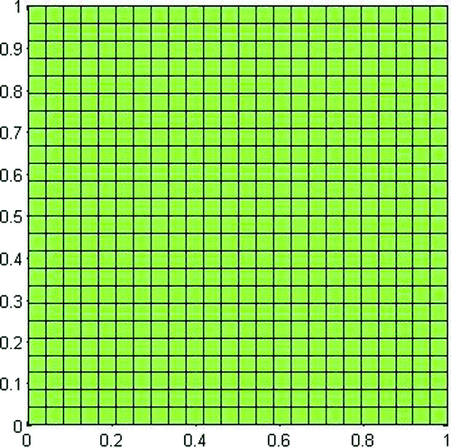
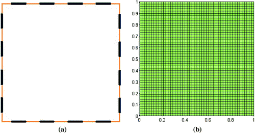
A numerical phantom was used to simulate the data acquired by an EIT system. The data were used to test the EIT image reconstruction algorithm. The phantom is a FDM discretized domain, whose conductivity distribution was previously chosen. Each phantom is a square divided into 49x49 units and composed of 2304 subsquare elements. On each side of the domain, four electrodes are distributed, totaling sixteen electrodes distributed along the domain border. The electrodes distribution and domain discretization are represented in Figure .
Figure 1. Numerical phantom used to simulate the data acquired by an EIT system: (a) Electrodes distribution and (b) domain discretization.
The electrical potentials measurement V at the numerical phantom boundary were acquired by the EIT forward problemFootnote2 solution, for each current patterns injected in
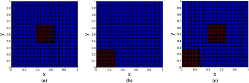
. Afterwards, these electrical potentials were used for an image estimation through the implemented SA algorithm. The results were compared to the numerical phantom conductivity distribution. Numerical phantom conductivity distributions were set to two different conductivity values. They are represented in Figure :
Figure 2. Phantom conductivity distributions. The areas in red have conductivity equal to 5 conductivity measurement units (cmu) and the blue colour region has conductivity equal to 2 cmu.
The MDF mesh used to solve the inverse problem is a square divided in units and composed of 576 subsquare elements. The mesh used for inverse problem is represented in Figure .
The objective function was calculated by Equation (Equation7(7)
(7) ). The parameter
was calculated through the iterative relation
and the scalar
was updated by expression (Equation10
(10)
(10) ).
Using the proposed approach and an initial value of , the following reconstructions were obtained for the phantoms showed on Figure :
Figure 4. Reconstructions of domains presented on Figure using the proposed SA approach. (a) Reconstruction for Figure (a); (b) reconstruction for Figure (b) and (c) reconstruction for Figure (c).

Herrera’s approach also was used to solve the inverse problem for phantoms of Figure. For these reconstructions, the decrease of the parameter T was controlled through the iterative expression and the initial value of T was set to 0.08. For each point, the value of step
was controlled by the expression (Equation10
(10)
(10) ). The obtained results are given below.
Figure 5. Reconstructions of domains presented on Figure using Herrera’s approach. (a) Reconstruction for Figure (a); (b) reconstruction for Figure (b) and (c) reconstruction for Figure (c).

It is difficult to quantify the accuracy of stochastic methods because each method can be implemented in many different ways [Citation32,Citation33]. However, qualitatively the constructions shown in Figures and seem to indicate that the newly proposed method has accuracy similar to the method presented by Herrera with much less computational cost. This happens because in Herrera’s approach each conductivity parameter is individually modified in a new iteration. Therefore, since it is necessary to solve the forward problem for every conductivity change, the computational cost for the solutions is quite high [Citation8].
In the tests, the search for best solutions ends up after a predetermined number of iterations. Such numbers were obtained by prior testing: for each method the average number of iterations required for the solution to stabilize has been verified.
The conductivity matrix is simultaneously updated in the proposed method and only one forward problem solution is required at every iteration. In turn, in the Herrera’s method each point of the matrix is updated individually and the conductivity is varied M times at the same point. In the present work, testing with virtual domains was performed with a conductivity matrix. For each matrix point, eight different values of conductivity were tested at every iteration. Thus, it has taken 5 millions of forward problem solutions to produce inversions by Herrera’s method. As the solution to the forward problem is responsible for almost all the computational cost of each method, it is possible to affirm that the proposed method is about 500 times less expensive than the Herrera’s method.
In this work, testing with virtual domains was performed with a conductivity matrix. For each matrix point, eight different values of conductivity were tested at every iteration. Thus, it has taken 5 million forward problem solutions to produce inversions by Herrera’s method. As the solution to the forward problem is responsible for almost all the computational cost of each method, it is possible to affirm that the proposed method is about 500 times less expensive than the method proposed by Herrera.
The parameter T has the objective of controlling the amount of conductivity distributions that are accepted. In the reconstructions shown in Figure , the parameter T was chosen in order to maintain the acceptance ratio of new configurations by 50%/60%. The graphs of the acceptance ratio as a function of the number of iterations are shown below in Figure :
Figure 6. Acceptance ratio as a function of the number of iterations for the reconstructions of Figure . In red, result for the reconstruction of Figure (a). In blue, result for the reconstruction of Figure (b). In green, result for the reconstruction of Figure (c).
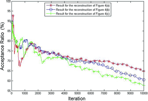
When the parameter T is high, it was possible to maintain an acceptance ratio above 70%. With the drop of parameter T, at the end of the iteration process, this number falls to 60%.
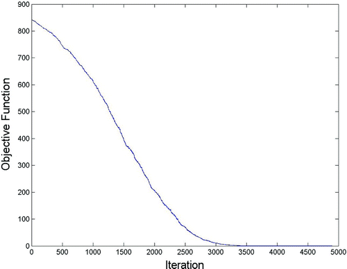
The evaluation of a method for inverse problems with synthetic data may be misleading, especially when one model is used both for data production and for its inversion [Citation34]. This fact can be attributed to the difference between the electrode potentials of the original model and the reconstructed one tends to zero. It can be observed in Figure , where the evolution of the cost function is showed for reconstruction depicted in Figure (a).
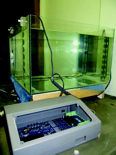
Despite being expected, this behaviour is unrealistic in practical applications, the simulated model will always differ from the physical system. Thus, it is necessary to evaluate the proposed reconstruction process when applied to data obtained from a real physical system [Citation8]. In order to do this, the proposed algorithm was used to obtain images of a transverse plane on a physical tank. The tank has 16 electrodes coupled to an electronic data acquisition system. The photo of the equipment is shown in Figure .
To solve EIT inverse problem, a computational domain was used to represent geometrically the tank and the electrodes positions. The MDF mesh used contain a square units and is composed of 660 subsquare elements. The mesh used and tank electrodes positions is represented in Figure .
Figure 9. (a) Mesh used in the image reconstruction from experimental data. (b) Schematic representation of the electrodes positions in the tank.

The practical algorithm tests were performed as a first stage in two different situations: a conductive or an insulating object immersed in water. At a second stage, a continuous laminar conductivity distribution composed by sand and coal powder was tested.
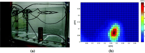
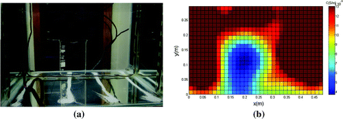
In the first experiment with a full tank of tap water, a brass cylinder with 5 cm base and 11 cm height was placed inside the tank, like it is shown in Figure (a).
The first experimental reconstruction (Figure (b)) indicated that the proposed approach could reproduce with good precision the size and position of the cylinder placed in the tank. In addition, the water conductivity calculated by the algorithm was approximately 0.016 S/m, consistent with the value reported by the Municipal Department of Water and Sewage of Porto Alegre (DMAE) – 0.013 S/m. The obtained value of the cylinder conductivity was underestimated; perhaps because brass has a large conductivity – about S/m – it theoretically requires more interactions to the algorithm to reach a more approximate value.
In the second experiment with a full tank of tap water, a glass beaker was placed inside the tank, as it is shown in Figure (a).
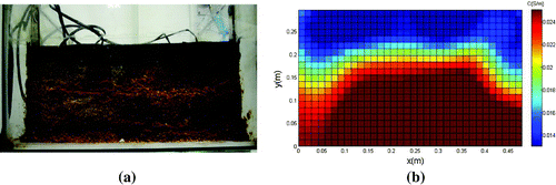
Figure (a) shows the physical model after the drying and slicing at a plane containing the electrodes. This photo is to be compared to the results provided by the reconstruction method.
The second experimental reconstruction (Figure (b)) indicated that the proposed approach could reproduce with good precision the size and position of an object placed inside the tank. Likewise, the water conductivity calculated by the algorithm was close to the value reported by the Municipal Department of Water and Sewage of Porto Alegre (DMAE) – 0.013 S/m. On the other hand, the beaker conductivity was overestimated,Footnote3 possibly for the same reasons stated above for the metal cylinder. In the third test, a layer of sand and a layer of mineral coal powder were deposited into the tank. The remainder of the tank was filled with tap water. Figure (a) shows the physical model after the drying and slicing at a plane containing the electrodes. This photo is to be compared to the results provided by the reconstruction method.
The conductivity of the sand and coal when mixed with tap water were measured in the laboratory using the techniques of electrical impedance spectroscopy and the four point probe method. The conductivity measured values for coal and sand were 0.050 and 0.024 S/m, respectively. The water used in this experiment was also analyzed by both methods and showed a conductivity of 0.01 S/m. The reconstruction shown in Figure (b) represents reasonably well the structure shown in Figure (a), although the expected conductivity values are different for sand and coal, being closer to the conductivity of water. This difference is probably due to the unconsolidated structure resulting in a high porosity and permeability.
7. Conclusions
In this work, a new approach to solve the EIT inverse problem was proposed by application of SA coupled to a smoothing stage realized by Gaussian low-pass filter. The results obtained from the computationally generated data showed that the proposed approach is computationally less expensive than a typical SA approach reported in the literature. Measurements performed in a tank show that the proposed method could satisfactorily estimate the position, the dimensions and the conductivity of different materials inside the tank. Considering the simplicity of the method and the accuracy of the results, the proposed method can be considered a good alternative to solve the EIT inverse problem.
Acknowledgements
Thanks to Prof. Juliano D’Ornelas Benfica for the design and development of the data acquisition system, Laura Córdova Matte and Aline Sanchez de Castro for the data collection system operation and the installation of sedimentary deposits, Michelle Guedes Perez and Ana Cecília Ferraz Loreto for help with simulations in Matlab. We acknowledge Petrobras for the permission to publish the results.
Additional information
Funding
Notes
No potential conflict of interest was reported by the authors.
1 It is important to establish the difference between ‘moves’ and ‘iterations’. An iteration occurs when all conductivity matrix is completely updated. A move is any modification of conductivity matrix.
2 To avoid an inverse crime, the mesh used in the phantom domain have more elements than the mesh used to solve the inverse problem. Moreover, measured data were generated using an iterative Gauss–Seidel method, whereas for the inverse problem solution, a successive over-relaxation method (SOR) was employed. The value of SOR weightage factor used was 1.7.
3 The electrical conductivity of glass varies due to the composition. Taking into account work of Bossa et al. [Citation35], the conductivity may assume values between and
S/m.
References
- Herrera CNL, Vallejo MFM, Moura FS, et al. Electrical impedance tomography algorithm using simulated annealing search method. Proc Int Cong Mech Eng. 2007;7033–7036.
- Ciulli S, Pidcock MK, Sebu C. An integral equation method for the inverse conductivity problem. Phys Lett A. 2004;325(3):253–267.
- Martins JS, Moura CS, Vargas RF. Avaliação de 3 diferentes aproximações para a solução do problema direto da tomografia de impedância elétrica. Revista Internacional de Métodos Numéricos para C\’{a}lculo y Diseño en Ingeniería. 2015;31(1):42–49.
- Das R. Inverse analysis of Navier--Stokes equations using simplex search method. Inverse Probl Sci Eng. 2012;20(4):445–462.
- Eppler K, Harbrecht H. A regularized Newton method in electrical impedance tomography using shape Hessian information. Control Cybern. 2005;34:203–225.
- Wang M. Inverse solutions for electrical impedance tomography based on conjugate gradients methods. Meas Sci Technol. 2002;13(1):101–117.
- Olmi R, Bini M, Priori S. A genetic algorithm approach to image reconstruction in electrical impedance tomography. IEEE Trans Evol Comput. 2000;4(1):83–88.
- De Castro Martins T, de Camargo EDLB, Gonzalez Lima R, et al. Image reconstruction using interval simulated annealing in electrical impedance tomography. IEEE Trans Biomed Eng. 2012;59(7):1861–1870.
- Kirkpatrick S, Gelatt CD, Vecchi MP. Optimization by simulated annealing Science. 1983;220(4598):671–680.
- Corana A, Marchesi M, Martini C, et al. Minimizing multimodal functions of continuous variables with the ‘Simulated Annealing Algorithm’. ACM Trans Math Softw. 1987;272–280.
- Martins TC, Tsuzuki M. Placement over containers with fixed dimensions solved with adaptive neighborhood simulated annealing. Bull Polish Acad Sci Tech Sci. 2009;57(3):273–280.
- Das R, Ooi KT. Application of simulated annealing in a rectangular fin with variable heat transfer coefficient. Inverse Probl Sci Eng. 2013;21(8):1352–1367.
- Bhowmik A, Singla RK, Roy PK, et al. Predicting geometry of rectangular and hyperbolic fin profiles with temperature-dependent thermal properties using decomposition and evolutionary methods. Energy Convers Manage. 2013;74:535–547.
- Betke M, Makris NC. Fast object recognition in noisy images using simulated annealing. In: Proceedings of Fifth International Conference on Computer Vision. Cambridge (MA): IEEE; 2015. p. 523–530.
- Abdessaied N, Soeken M, Dueck GW, et al. Reversible circuit rewriting with simulated annealing. In: 2015 IFIP/IEEE International Conference on Very Large Scale Integration (VLSI-SoC). Daejeon, South Korea: IEEE; 2015. p. 286–291.
- Denai MA, Mahfouf M, Mohamad-Samuri S, et al. Absolute electrical impedance tomography (aEIT) guided ventilation therapy in critical care patients: simulations and future trends. IEEE Trans Inform Technol Biomed. 2010;14(3):641–649.
- Aykroyd RG, Cattle BA. A boundary-element approach for the complete-electrode model of EIT illustrated using simulated and real data. Inverse Probl Sci Eng. 2007;15(5):441–461.
- Kolehmainen V, Lassas M, Ola P, et al. Recovering boundary shape and conductivity in electrical impedance tomography. Inverse Probl Imaging. 2013;7(1):217–242.
- Kim KY, Kim BS, Kim MC, et al. Regularized modified Newton Raphson algorithm for electrical impedance tomography based on the exponentially weighted least square criterion. In: Proceedings TENCON 2000. Vol. 1; Kuala Lumpur, Malaysia: IEEE; 2000. p. 64–68.
- Artola J, Dell J. Broyden quasi-Newton method applied to electrical impedance tomography. Electron Lett. 1994;30(1):27–28.
- Player MA, Van Weereld J, Hutchison JMS, et al. An electrical impedance tomography algorithm with well-defined spectral properties. Meas Sci Technol. 1999;10(3):L9–L14.
- Tikhonov AN, Arsenin VY. Solution of ill-posed problems. Washington (DC): Wiley; 1977.
- Tarvainen M, Vauhkonen M, Savolainen T, Kaipio JP. Boundary element method and internal electrodes in electrical impedance tomography. Int J Numer Methods Eng. 2001;50(4):809–824.
- Fan WR, Wang HX. Maximum entropy regularization method for electrical impedance tomography combined with a normalized sensitivity map. Flow Meas Instrum. 2010;21(3):277–283.
- de Campos Velho HF. Problemas inversos: conceitos b\’{a}sicos e aplicações. In: Anais do Encontro de Modelagem Computacional. Mini-curso; Nova Friburgo; 2001. p. 63–79.
- Chiang YW, Borbat PP, Freed JH. Maximum entropy: a complement to Tikhonov regularization for determination of pair distance distributions by pulsed ESR. J Magn Reson. 2005;177(2):184–196.
- Lampinen J, Vehtari A, Leinonen K. Using Bayesian neural network to solve the inverse problem in electrical impedance tomography. In: Proceedings of 11th Scandinavian Conference on Image Analysis. Vol. 1; Kangerlussuaq, Greenland; 1999. p. 87–94.
- Metropolis N, Rosenbluth AW, Rosenbluth MN, Teller AH, Teller E. Equation of state calculations by fast computing machines. J Chem Phys. 1953;21(6):1087–1092.
- Lutfiyya H, McMillin B, Poshyanonda P, Dagli C. Composite stock cutting through simulated annealing. Math Comput Model. 1992;16(1):57–74.
- Martins TC, Fernandes AV, Tsuzuki MSG. Image reconstruction by electrical impedance tomography using multi-objective simulated annealing. In: 2014 IEEE 11th International Symposium on Biomedical Imaging (ISBI). Beijing, China: IEEE; 2014. p. 185–188.
- Goldberg DE, Holland JH. Genetic algorithms and machine learning. Machine learn. 1988;3(2):95–99.
- Wright MB. An overview of neighbourhood search metaheuristics. Working Paper 087. Lancaster University Management School; 2003.
- Eglese RW. Simulated annealing: a tool for operational research. Eur J Oper Res. 1990;46(3):271–281.
- Colton D, Kress R. Inverse acoustic and electromagnetic scattering theory (Vol. 93). Springer Science & Business Media; 2012.
- Bossa TH, D\’{\i}az-Mora N, Buchner S, et al. Estudo da condutividade elétrica de vidros de isoladores de linhas de transmissão HVDC dopados. In: Congresso da Academia Trinacional de Ci{\^e}ncias, II; Foz do Iguaçu, Paraná; 2007.

