 ?Mathematical formulae have been encoded as MathML and are displayed in this HTML version using MathJax in order to improve their display. Uncheck the box to turn MathJax off. This feature requires Javascript. Click on a formula to zoom.
Abstract
In this study, we examined the effects of a hollow cylindrical tube’s thickness and material properties on estimated time delay and waveform distortion in a one-dimensional inverse heat transfer analysis model using the thermal resistance method and an input estimation algorithm. Results indicated a persistent time delay for various heat flux amounts applied to different tube thicknesses. As the tube thickness increased, the numerically determined temperature data also experienced a time delay, which affected the inverse heat transfer response curve. Results also indicated that the transient heat flux waveform estimated for different material properties showed higher levels of distortion for materials having relatively low thermal conductivity. These materials also exhibited greater time delays. To address these issues, we applied a Fourier number (a dimensionless number representing the tube’s thickness and material properties) and proposed an equation to calculate sharpness, which can subsequently be used to predict probable time delays and heat flux waveform distortion. In conclusion, a correction is required when a low Fourier number is used in inverse heat transfer analysis.
1. Introduction
Recent advancements in numerical analysis algorithms and computer performance have expanded the application of numerical analysis methods that model physical phenomena. For example, recent direct heat transfer analysis methods enable not only mathematical modelling but also internal temperature distribution prediction. To accurately estimate such physical phenomenon using numerical analysis, the boundary and initial conditions, as well as the physical properties of an object, are required. If a particular boundary condition is unknown, inverse (rather than direct) heat transfer analysis methods should be used to derive the boundary condition and internal temperature distribution. Generally speaking, the mathematical modelling of an object and mathematical tools that calculate unknown physical quantities or properties are necessary for inverse heat transfer analysis. For this reason, inverse heat transfer analysis is mathematically more complex and computationally costly than conventional direct heat transfer analysis. Therefore, it is important to select an appropriate numerical method for conducting inverse heat transfer analysis effectively.
Many researchers have previously proposed various analytical or numerical methods for inverse heat transfer analysis. Integral or Laplace transform techniques were initially proposed to solve inverse heat transfer problems in a one-dimensional unsteady state and applicable to simple shapes [Citation1–3]. In later studies, researchers attempted to overcome analytical method limits by focusing on sequential estimation methods [Citation4–6] and the conjugated gradient method [Citation7–10], which were applicable to various shapes. The conjugated gradient method is a simple, effective and iterative method to solve linear and non-linear problems. Comparatively, the recursive input estimation algorithm, which estimates unsteady states by considering variances in each variable (e.g. time error), can produce results that approximate actual physical quantities [Citation11–14].
In this study, we conducted an inverse heat transfer analysis using the recursive input estimation algorithm to determine the effects of a hollow cylindrical tube’s thickness and material properties. Unlike prior studies that have used computationally intensive finite element methods to perform system modelling [Citation15–18], we used the finite differential thermal resistance network method to perform heat transfer modelling. This method typically expresses differential equation derivative terms as a Taylor series, significantly reducing computational requirements and supporting widespread application. Researchers have previously used this method to estimate the internal temperature of a motor [Citation19,20].
In recent studies, researchers have attempted to improve the accuracy of inverse heat transfer analysis by estimating various temperature-dependent thermophysical properties [Citation21–24]. However, these studies did not adequately explain or offer responses to the variations in estimated values of the thermophysical properties. Further, it has also been reported that the estimated heat flux using these methods is inaccurate for large thicknesses [Citation25].
To overcome the shortcomings of prior studies, we offer both an explanation for and a response to variations in heat transfer analysis results. Specifically, in this study, we applied the thermal resistance method and a recursive input estimation algorithm to characterize the effects of tube thickness and material properties on heat transfer analysis results and proposed the use of a dimensionless Fourier number to address issues with time delays and heat flux waveform distortion.
2. Model description
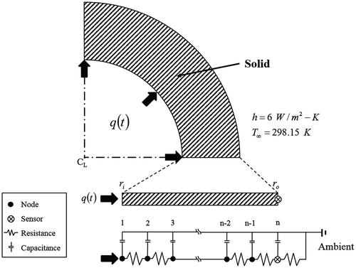
Figure shows the simply shaped hollow cylindrical tube used for the inverse heat transfer analysis in this study. Because of its symmetrical shape, only ¼ of the tube’s cross section is shown. The effects of tube thickness and material properties on the inverse heat transfer analysis were verified by applying different inner (r i) and outer (r o) tube radii and using different tube materials including stainless steel, steel, rhodium and copper that offered different thermal conductivities (k) to identify response characteristics and the effects of such variables.
In this study, inner tube radii were selected as 0.0005, 0.0025, 0.005, 0.0075, 0.01 and 0.015 m. Outer tube radii were determined to have thickness variations as 0.001, 0.005, 0.01, 0.015, 0.02 and 0.03 m, which enabled the effect of tube thickness to be identified. Table lists the properties of each material. Although rhodium is primarily used as an electroplating rather than a structural material, it contributed to this study’s objective to identify response characteristics within a certain range of thermal conductivity.
Table 1. Material properties and boundary conditions of hollow cylindrical tubes.
The heat flux boundary condition (q) caused by high-temperature and high-pressure fluid was specified at the internal boundary of the tube. Comparatively, the natural convection boundary condition () was applied to the external part of tube that is exposed to air. The high-temperature and high-pressure fluid in the tube prevents direct measurement of the heat flux. Instead, the heat flux inside the tube can be inversely estimated using measurements obtained by a sensor (⊗) mounted on the external surface of the tube and inverse heat transfer analysis. Other material properties of the tube (e.g. density, thermal conductivity, specific heat) were assumed to be constant for each tube.
The governing equation for one-dimensional transient heat conduction based on the above boundary conditions and assumptions is given in Equation (Equation1(1)
(1) ). Equation (Equation2
(2)
(2) ) specifies initial conditions and Equations (Equation3
(3)
(3) ) and (Equation4
(4)
(4) ) specify the boundary conditions.
(1)
(1)
(2)
(2)
(3)
(3)
(4)
(4)
In this study, a thermal resistance network was used for heat transfer modelling. Thermal resistance networks apply electrical resistance concepts to heat transfer, based on similarities between thermal and electrical conductivities. The thermal resistance network for the tube was configured using the resistance equations of conduction () and convection (
) between material points that are expressed as follows:
(5)
(5)
(6)
(6)
The inverse heat transfer analysis model in this study was intended to analyze unsteady states by observing variations over time. Accordingly, a heat capacity term was added to achieve an unsteady state. This heat capacity term can be expressed as follows:(7)
(7)
Using the governing equation in Equation (Equation1(1)
(1) ) and the boundary conditions specified in Equations (Equation3
(3)
(3) ) and (Equation4
(4)
(4) ), a relationship between nodal points can be determined by the following thermal resistance equations:
(8)
(8)
(9)
(9)
(10)
(10)
Subsequently, the system modelling equation for these nodal points can be expressed by the following matrix equation using the thermal resistance method:(11)
(11)
where is the capacitance matrix indicating an unsteady state,
is the temperature vector representing the temperature of each nodal point,
is the conductance matrix indicating the thermal conductivity of the tube,
is the thermal load vector of heat flux representing the heat flux on the surface of tube, and
is the thermal load vector of convection representing convection outside of the tube.
To numerically solve the unsteady state term in Equation (Equation11(11)
(11) ), the time difference can be expressed as a Taylor’s series as follows [Citation26]:
(12)
(12)
where t is time and Δt is the sampling interval. By introducing a time-stepping parameter (θ) into Equation (Equation12(12)
(12) ), a time difference equation for temperature can be expressed as follows.
(13)
(13)
where θ values of 0.0, 0.5 and 1.0 reflect a fully explicit scheme in the forward difference method, a semi-implicit scheme in the Crank–Nicolson method, and a fully implicit scheme in the backward difference method, respectively.
Substituting Equations (Equation12(12)
(12) ) and (Equation13
(13)
(13) ) into Equation (Equation11
(11)
(11) ), the following relationship results:
(14)
(14)
Because the convection condition outside of the tube is assumed to be constant, . This study considered the fully implicit scheme in the backward difference method when θ = 1.0. Accordingly, Equation (Equation14
(14)
(14) ) can be rearranged as a state equation for time as follows:
(15)
(15)
where X is the state vector, Φ is the state transition matrix and κ is time. Additionally, Γ1 and Γ2 are input matrices, and q is a deterministic input sequence. Also, ω is the process noise vector, and Λ is the coefficient matrix. The equations for X, Φ, Γ1, Γ2 and Λ are as follows:(16)
(16)
(17)
(17)
(18)
(18)
(19)
(19)
(20)
(20)
To estimate heat flux using temperature measurements, an input estimation approach for inverse heat transfer analysis was required. This approach comprised a Kalman filter and a recursive least squares algorithm. The algorithm derivation process is detailed in [Citation15,18]. The Kalman filter can be sequentially calculated as follows [Citation27–29]:(21)
(21)
(22)
(22)
(23)
(23)
(24)
(24)
(25)
(25)
(26)
(26)
(27)
(27)
where is the input estimator, P is the filter’s error covariance matrix, Q is the process noise covariance, s is the innovation covariance, H is the measurement matrix, R is the measurement noise covariance, Z is the observation vector and
is the bias innovation.
Similarly, the calculation method for the recursive least squares algorithm is as follows [Citation27–29]:(28)
(28)
(29)
(29)
(30)
(30)
(31)
(31)
(32)
(32)
where B and M are sensitivity matrices, I is an identity matrix, K
b is the correction gain, γ is the forgetting factor, P
b is the error covariance of the estimated input vector and is the estimated input vector.
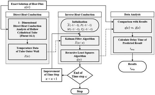
Figure shows the inverse heat transfer analysis method used in this study. The true heat flux () was initially input into the model. The temperature on the external surface of the tube (
) was determined using a direct heat transfer method. The FLUENT 16.1 commercial software programme was used to perform the direct heat transfer analysis. The temperature on the external surface of the tube was expressed as an observation matrix as follows:
(33)
(33)
where is the observation vector, His the measurement matrix and
is the measurement noise vector.
These temperatures obtained by the direct heat transfer analysis were subsequently used during the inverse heat transfer analysis to predict heat flux () inside the tube at a specified time. Specifically, the heat flux inside the tube was estimated using an input estimation algorithm comprising the Kalman filter and recursive least squares algorithm.
Because the process noise and measurement noise covariances could significantly affect the input estimation algorithm, it was necessary to determine their appropriate values in each analysis model. A prior study [Citation26] examined the effect of such values and proposed a range of appropriate values. Based on the results of this prior study, values for the process noise covariance (Q), measurement noise covariance (σ) and forgetting factor (γ) were set to 10, 10−3 and 0.925, respectively, in this study. In addition, the sampling interval (Δt), necessary for unsteady–state numerical analysis, was set to 0.01 s. It was assumed that the initial temperature both inside and outside of the tube prior to heat flux was T 0 = 298.15 K and the initial temperature was maintained outside of the tube.
A simple square wave was used to define the heat flux condition and determine the effects of tube thickness and material properties as follows:(34)
(34)
The temperature data numerically determined by FLUENT 16.1 for the outside area of the tube was set equal to the temperature on the external surface of the tube (used in the inverse heat transfer analysis to estimate heat flux). To identify the effects of heat flux on estimation, the following conditions for the square wave heat flux were defined:(35)
(35)
(36)
(36)
This process was repeated for various tube thicknesses and material properties and the corresponding response characteristics were verified.
To address issues of time delay and waveform distortion, we applied a Fourier number (a dimensionless number representing the tube’s thickness and material properties) and proposed an equation to calculate sharpness, which can subsequently be used to predict probable time delays and heat flux waveform distortion. First, the estimated heat flux from the model was compared with the true heat flux value input initially to calculate time delay (t
delay). A relationship for the temperature-based time delay was defined as follows:(37)
(37)
where T
0,max is the maximum temperature that can be measured outside the tube following the application of heat flux, and t
delay,T is the duration in which the initial surface temperature (T
0,initial) of the tube rises by 20%. A relationship for the heat flux-based time delay was also defined as follows:(38)
(38)
where q max is the maximum amount of heat flux and t delay,H is the duration in which the estimated heat flux increases by 20%.
Next, a dimensionless Fourier number was introduced to define the relationship between t
delay,H and tube thickness and material properties. The Fourier number was defined as follows:(39)
(39)
where the tube thickness was used as the characteristic length (L).
Lastly, the concept of sharpness was introduced to quantify the degree of heat flux waveform distortion. The sharpness (ψ) was defined as follows:(40)
(40)
In other words, the sharpness was defined to compare the angle of the rising part of a waveform between the exact heat flux profile and the estimated profile. Therefore, the smaller the sharpness, the more accurately the estimated heat flux profile simulated the exact heat flux profile.
3. Results and discussion
Figure shows the temperature change on the external surface of the steel tube for different tube thicknesses following application of the square wave heat flux determined in Equation (Equation34(34)
(34) ). In Figure (a), the inner radius of the tube was constant but the outer radius varied; in Figure (b), both the inner and outer radii of the tube varied. As overall tube thickness increased, the temperature on the external surface of the steel tube decreased. Similarly, as the inner tube radius increased, the temperature on the external surface of the steel tube decreased. The increased tube thickness increased thermal resistance and thus decreased thermal diffusion.
Figure 3. Variation of temperature at the outer wall of the hollow cylindrical tube during 30 s when a transient heat flux profile in Equation (Equation34(34)
(34) ) was applied to the inner wall of the tube: (a) constant inner radius, and (b) various inner radius.
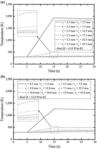
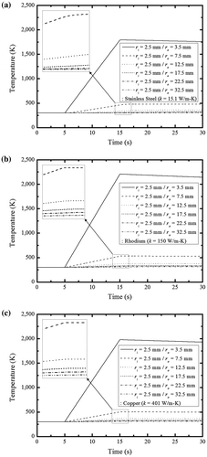
Figure shows the temperature change on the external surface of the tube for different material properties following application of the square wave heat flux determined in Equation (Equation34(34)
(34) ). Figure (a)–(c) reflect the results for the stainless steel, rhodium and copper tubes, respectively. In each case, the inner radius of the tube was constant but the outer radius varied by concurrently changing tube thickness. These temperature results indicated that increased thermal conductivity facilitated thermal diffusion and subsequently increased the temperature on the external surface of the tube. However, as shown in Figure (b) and (c), differences in both thermal conductivity and thermal capacity affected temperature measurements. For example, higher external temperatures were observed for the lower thermal conductivity rhodium tube than the higher thermal conductivity copper tube; rhodium has a lower thermal capacity than copper and thus stores less energy in the tube.
Figure 4. Variation of temperature at the outer wall of the hollow cylindrical tube during 30 s when a transient heat flux profile in Equation (Equation34(34)
(34) ) was applied to the inner wall of the tube: (a) stainless steel, (b) rhodium and (c) copper.
Using the square wave heat flux conditions defined in Equations (Equation34(34)
(34) )–(Equation36
(36)
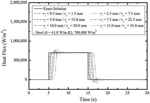
(36) ), Figure shows the estimated heat flux for different steel tube thicknesses and heat flux levels. The results indicated that the time delay of heat flux increased as tube thickness increased. One explanation for this phenomenon may be that the numerically determined temperature data experiences a time delay based on tube thickness or material property characteristics that is subsequently manifested in the inverse heat transfer analysis results. Another explanation may originate from the process noise and measurement noise covariances and forgetting factor, which were defined for stable inverse heat transfer analysis. However, these latter factors are less influential than the time delay from the temperature data and cannot be improved by modifying their set values. Figure (b) and (c) show the combined effects of tube thickness and heat flux levels. In each case, the level and form of the heat flux were accurately estimated, even for low levels of heat flux (70 and 7000 W/m2) and with a time delay. However, heat flux was overestimated with a 1–2 s time delay after the analysis programme stabilized; the overestimation percentage increased as the applied heat flux decreased. Consequently, sensitivities to stabilization error should be considered for low levels of estimated heat flux.
Figure 5. Predicted transient heat flux profiles of different heat flux levels for steel tubes: (a) q = 700, 000 W/m2, (b) q = 7, 000 W/m2 and (c) q = 70 W/m2.
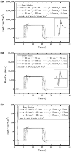
Figure shows heat flux estimates when both the inner and outer radii of the steel tube varied. In conventional commercial tubes, increases to the inner radius also increase tube thickness. Accordingly, to simulate such tubes used in practice, an inverse heat transfer analysis was performed with varying inner radii and tube thicknesses. The estimation results were similar to those observed previously for the case of fixed inner but variable outer tube radii. The time delay increased as the inner radius and tube thickness increased. These collective observations suggest that tube thickness is more influential than the inner radius of the tube.
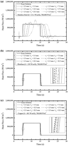
Next, we examined the effects of the tube’s material properties on heat flux estimation. Using the temperature data presented previously in Figure , Figure (a)–(c) show the heat flux estimates for the stainless steel, rhodium and copper tubes, respectively. Both the copper and rhodium tubes, which have high thermal conductivity, exhibited a time delay related to tube thickness but a stable waveform. Comparably, the stainless steel tube, which has a low thermal conductivity, exhibited an increased time delay and a distorted waveform. Consequently, when analyzing inverse heat conduction under low thermal conductivity, the temperature should be measured where the tube thickness is minimized to reduce time delay and waveform distortion and subsequently increase estimation accuracy.
Figure 7. Predicted transient heat flux profile for hollow cylindrical tubes according to tube material: (a) stainless steel, (b) rhodium (c) copper.
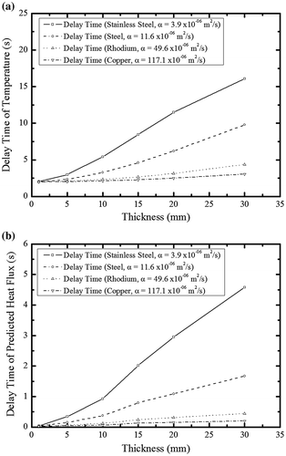
Based on these previous findings, Figure characterizes the observed time delays for different tube thicknesses and material properties. Figure (a) shows the time delay (t delay,T) results determined using the temperature data measured on the external surface of the tube. The results indicated that t delay,T decreased as either thermal conductivity increased or tube thickness decreased. For tubes having low thermal conductivity, the effect of thickness was greater. Comparably, Figure (b) shows the time delay (t delay,H) results determined using the estimated heat flux. Again, the results indicated that t delay,H decreased as either thermal conductivity increased or tube thickness decreased. For tubes having low thermal conductivity, the effect of thickness was again greater.
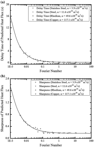
As a dimensionless number representing a relative ratio between a tube’s thermal conductivity and thermal storage, the Fourier number indicates variation in thermal conductivity attributable to the tube’s different material properties and variation in thermal storage attributable to different tube thicknesses. Figure (a) shows the relationship between the Fourier number and t
delay,H. The delay time of predicted heat flux decreased as the Fourier number increased. This graphical relationship was expressed numerically as follows:(41)
(41)
This numerical relationship, derived from this study’s analysis results, can be used to estimate t delay,H for different tube thicknesses and material properties during inverse heat transfer analysis.
Figure (b) shows the relationship between the Fourier number and the estimated sharpness. Intervals with steep increases or decreases in heat flux exhibited time delays attributable to tube thickness or material properties and distorted waveforms. The gradient was determined by measuring the durations for which 20 and 80% of the maximum heat flux were obtained, respectively. As shown in Figure (a) and (b), as Fourier number increased, t
delay,H and sharpness rapidly decreased and reached a minimum value. This is due to the fact that even though well-made algorithm was activated, system delayed time could not be avoided. This graphical relationship was expressed numerically as follows:(42)
(42)
This numerical relationship, also derived from this study’s analysis results, can be used to relate the sharpness with tube thicknesses and material properties during inverse heat transfer analysis.
4. Conclusions
In this study, we investigated the response characteristics of a one-dimensional inverse heat transfer analysis model for a hollow cylindrical tube with different tube thicknesses and material properties using a thermal resistance method and an input estimation algorithm. We used the FLUENT 16.1 software to determine temperatures on the external surface of various tubes with different thicknesses and material properties thereby identifying the effect of these variables. The temperatures determined by solving the direct heat conduction problem with the use of the FLUENT were subsequently applied to the inverse heat transfer analysis to estimate heat flux. Results indicated a recurring time delay regardless of heat flux levels and tube thicknesses. However, as tube thickness increased, the temperature data determined numerically exhibited a time delay across tube thicknesses and material properties thereby affecting the inverse heat transfer response curve. Results also indicated that for materials with a relatively low thermal conductivity, temperature should be measured where tube thickness is minimized to reduce time delay and waveform distortion and subsequently increase estimation accuracy. Finally, we proposed an equation to calculate sharpness in conjunction with the use of a Fourier number, which enables time delay and waveform distortion prediction for various tube thicknesses and material properties. If too low of a Fourier number is applied during inverse heat transfer analysis, significant time delay and severe waveform distortion can occur, requiring a correction.
Funding
The work was supported by the Railway Technology Research Project by Ministry of Land, Infrastructure and Transport Republic of Korea [grant number 17RTRP-B082486-04].
Disclosure statement
No potential conflict of interest was reported by the authors.
| Nomenclature | ||
| A | = | area, m2 |
| B | = | sensitivity matrix |
| [C] | = | capacitance matrix |
| C | = | heat capacity, J/K |
| C p | = | specific heat capacity, J/kg⋅K |
| E | = | element number |
| {F} | = | thermal load vector |
| h | = | convection heat transfer coefficient, W/m2⋅K |
| H | = | measurement matrix |
| I | = | identity matrix |
| k | = | thermal conductivity, W/m⋅K |
| K | = | Kalman gain |
| K b | = | steady-state correction gain |
| l | = | length, m |
| L | = | characteristic length, m |
| M | = | sensitivity matrix |
| [M] | = | conductance matrix |
| O | = | error order |
| P | = | filter’s error covariance matrix |
| P b | = | error covariance matrix |
| q | = | deterministic input (heat flux), W/m2 |
|
| = | estimated input vector, W/m2 |
| Q | = | process noise covariance |
| r | = | radius, m |
| R | = | measurement noise covariance |
| Re | = | thermal resistance, K/W |
| s | = | innovation covariance |
| t | = | time, s |
| {T} | = | temperature vector |
| T | = | temperature, K |
| T ∞ | = | ambient temperature, K |
| T 0 | = | initial temperature, K |
| V | = | volume, m3 |
| X | = | state vector |
|
| = | input estimator |
| Z | = | observation vector |
|
| = | bias innovation |
| Greek letters | ||
| α | = | thermal diffusivity, m2/s |
| γ | = | forgetting factor |
| Γ | = | input matrix |
| θ | = | time-stepping scheme parameter |
| κ | = | discretized time |
| Λ | = | coefficient matrix |
| ν | = | measurement noise vector |
| ρ | = | density, kg/m3 |
| σ | = | measurement noise covariance |
| τ | = | Fourier number |
| Φ | = | state transition matrix |
|
| = | sharpness |
| ω | = | process noise vector |
| Superscripts | ||
| n | = | time domain |
| Subscripts | ||
| co | = | copper |
| cond | = | conduction |
| conv | = | convection |
| delay | = | delay time |
| H | = | heat flux |
| i | = | inner |
| initial | = | initial |
| material | = | material |
| max | = | maximum |
| o | = | outer |
| r | = | radial direction |
| rh | = | rhodium |
| s | = | steel |
| ss | = | stainless steel |
| T | = | temperature |
References
- Stolz G . Numerical solutions to an inverse problem of heat conduction for simple shapes. J Heat Transf. 1960;82:20–25.
- Beck JV . Surface heat flux determination using an integral method. Nucl Eng Des. 1968;7:170–178.
- Woo KC , Chow LC . Inverse heat conduction by direct inverse Laplace transform. Numer Heat Transfer. 1981;4:499–504.
- Beck JV , Blackwell B , Clair CR St Jr . Inverse heat conduction: Ill-posed problems. New York(NY): John Wiley & Sons; 1985.
- Beck JV . Nonlinear estimation applied to the nonlinear inverse heat conduction problem. Int J Heat Mass Tran. 1970;13:703–716.
- Blackwell BF . Efficient technique for the numerical solution of the one-dimensional inverse problem of heat conduction. Numer Heat Transfer. 1981;4:229–238.
- Jarny Y , Ozisik MN , Bardon JP . A general optimization method using adjoint equation for solving multidimensional inverse heat conduction. Int J Heat Mass Tran. 1991;34:2911–2919.
- Huang CH , Ozisik MN . Inverse problem of determining the unknown strength of an internal plane heat source. J Franklin I. 1992;329:751–764.
- Silva Neto AJ , Ozisik MN . Simultaneous estimation of location and timewise-varying strength of a plane heat source. Numer Heat Tr A-Appl. 1993;24:467–477.
- Bokar JC , Ozisik MN . An inverse analysis for estimating the time-varying inlet temperature in laminar flow inside a parallel plate duct. Int J Heat Mass Tran. 1995;38:39–45.
- Chan YT , Hu AGC , Plant JB . A Kalman filter based tracking scheme with input estimation. IEEE T Aero Elec Sys. 1979;AES-15:237–244.
- Hou M . Comments on “Tracking a maneuvering target using input estimation”. IEEE T Aero Elec Sys. 1989;AES-25:280.
- Bogler PL . Tracking a maneuvering target using input estimation. IEEE T Aero Elec Sys. 1987;AES-23:298–310.
- Farooq M , Bruder S . Comments on “Tracking a maneuvering target using input estimation. IEEE T Aero Elec Sys. 1989;AES-25:300–302.
- Ji CC , Tuan PC , Jang HY . A recursive least-squares algorithm for on-line 1-D inverse heat conduction estimation. Int J Heat Mass Tran. 1997;40:2081–2096.
- Wang BL , Mai YW . Transient one-dimensional heat conduction problems solved by finite element. Int J Mech Sci. 2005;47:303–317.
- Daouas N , Radhouani MS . A new approach of the Kalman filter using future temperature measurements for nonlinear inverse heat conduction problems. Numer Heat Tr B-Fund. 2004;45:565–585.
- Chen TC , Liu CC , Jang HY , et al . Inverse estimation of heat flux and temperature in multi-layer gun barrel. Int J Heat Mass Tran. 2007;50:2060–2068.
- Mellor PH , Roberts D , Turner DR . Lumped parameter thermal model for electrical machines of TEFC design. IEE Proc-B. 1991;138:205–218.
- Mezani S , Takorabet N , Laporte B . A combined electromagnetic and thermal analysis of induction motors. IEEE T Magn. 2005;41:1572–1575.
- Dantas LB , Orlande HRB . A function estimation approach for determining temperature-dependent thermophysical properties. Inverse Probl Eng. 1996;3:261–279.
- Zueco J , Alhama F . Simultaneous inverse determination of temperature-dependent thermophysical properties in fluids using the network simulation method. Int J Heat Mass Tran. 2007;50:3234–3243.
- Mota CAA , Orlande HRB , De Carvalho MOM , et al . Kolehmainen V, Kaipio JP. Bayesian estimation of temperature-dependent thermophysical properties and transient boundary heat flux. Heat Transfer Eng. 2010;31:570–580.
- Zhou J , Zhang Y , Chen JK , et al . Inverse estimation of surface heating condition in a finite slab with temperature-dependent thermophysical properties. Heat Transfer Eng. 2011;32:861–875.
- Huang CH , Wang SP . A three-dimensional inverse heat conduction problem in estimating surface heat flux by conjugate gradient method. Int J Heat Mass Tran. 1999;42:3387–3403.
- Chen TC , Liu CC . Inverse estimation of time-varied heat flux and temperature on 2-D gun barrel using input estimation method with finite-element scheme. Defence Sci J. 2008;58:57–76.
- Tuan PC , Hou WT . Adaptive robust weighting input estimation method for the 1-D inverse heat conduction problem. Numer Heat Tr B-Fund. 1998;34:439–456.
- Tuan PC , Ju MC . The validation of the robust input estimation approach to two-dimensional inverse heat conduction problems. Numer Heat Tr B-Fund. 2000;37:247–265.
- Lee WS , Ko YH , Ji CC . A study of an inverse method for the estimation of impulsive heat flux. J Franklin I. 2000;337:661–671.

