 ?Mathematical formulae have been encoded as MathML and are displayed in this HTML version using MathJax in order to improve their display. Uncheck the box to turn MathJax off. This feature requires Javascript. Click on a formula to zoom.
Abstract
In this research, the trends of degradation of stiffness and compressive strength of mass concrete of the Dez concrete arch dam, over time have been evaluated using a new and robust method. In previous studies of the corresponding author, he was successful to estimate the degradation of the stiffness of dam’s concrete at the end of a selected time interval, i.e. the Year 2007 from the interval 1965–2007 using a novel thermal inverse analysis. But, he was interested in knowing the trend of this degradation over that time interval. In previous studies, the author used isotropic and transversely isotropic elastic material models for evaluating the stiffness degradation. By these material models, the reduction of the compressive strength of the mass concrete could not be determined. In this new attempt, to overcome the above-mentioned shortcomings, it was decided that the time interval is limited to a maximum of one year from 1965 to 2007. In addition, a more sophisticated material model for concrete of the dam, named as, concrete damaged plasticity model, from the ABAQUS standard material library, was employed to simulate the long-term concrete behaviour. By this material model, the reduction of the compressive strength of the dam’s concrete could be measured. Obtained results demonstrated that the reduction of stiffness and strength of dam’s concrete have not a constant rate of change and they have been accelerated considerably after passing approximately 20 years from the commissioning of the dam.
1. Introduction
Mechanical behaviour of concrete material used in a constructed facility does not remain constant during its lifetime and is changing gradually over time. The nature and the rate of this change depend on many factors among them the environmental conditions; predominant applied external loads and the shape of the concrete structure have the major contributions.
Detection of the trend of this change over time is a key point in prediction of the long-term behaviour of a concrete structure, especially when the designer is faced with the stability assessment of an old huge concrete structure like an arch dam. The Dez Dam is a good example of such structures. The construction of this dam started in 1962 and completed in 1965. The dam has reached the age of half century, and is still one of the most important dams in Iran from the viewpoints of irrigation, water supply, power generation and flood control.
By performing novel thermal inverse analyses in previous studies of the author [Citation1,2], it was demonstrated that the aggressive environment of the Dez Dam has deteriorated the concrete material of this dam. Although these results are against to the normal long-term behaviour of concrete predicted by fib model code represented by Fédération International du Béton [Citation3], but these numerical predictions were in complete agreement with the evidence reported by Banian Pey Consultant Engineering Company which has recently completed an identifying survey and laboratory tests on the strength and Young modulus of the Dez Dam and its support [Citation4]. The experimental test results presented by this company confirm that the compressive strength and Young modulus of the dam have decreased compared to their initial values. As it was explained in detail in previous studies of the author on this dam [Citation1,2], it can be realized that the environmental conditions of the Dez Dam are special conditions that can be categorized as aggressive conditions and are not similar to the normal climate conditions considered for the other arch dams which their behaviours have investigated until today [Citation5–8]. Hence, the long-term behaviour of concrete of the Dez Dam cannot be classified as a normal behaviour according to the reference [Citation3].Therefore, due to this important fact, the previous numerical model results of the author and the experimental results show that the stiffness and strength of mass concrete of the Dez Dam do not increase with time and have been degraded heterogeneously and orthotropically over time under the effects of high-temperature and moisture fluctuations [Citation1,2,4]. As it was mentioned in [Citation2], besides to the aggressive climate conditions, the creep of the concrete in the Dez Dam is inevitable and this factor can increase the ductility of the dam which can indirectly results in reduction of the stiffness of the dam. In this study, the creep of the concrete could not be contributed directly by the material model assumed for the concrete in the inverse analysis. So, the effect of this factor can be seen indirectly by the reduction in Young and shear moduli. Heterogeneity mentioned earlier means that all parts of the dam have not experienced a same degradation. Furthermore, those studies revealed that the predominant state of the distributed stresses within the dam structure resulted from the applied loads and the shape of the dam makes this ongoing degradation anisotropic. This means that, in a fixed point of the dam, the degradation performance was not the same for all directions.
In the above-mentioned authors’ previous studies, two different material models were implemented for evaluating the concrete behaviour in the finite element simulations and some of their obtained results were used in a novel inverse analysis. At the first one, an isotropic homogeneous elastic behaviour and in the second, a transversely isotropic heterogeneous elastic behaviour was assigned for the concrete material simulation. Two years were selected for the time interval required in the above-mentioned inverse analyses, the Year 1965 as the beginning and the Year 2007 as the end of that interval. After comparison of obtained results, it was revealed that the objective error function defined in the inverse analysis by the authors was obtained smaller using the second model. This indicated that the degradation process makes the initial isotropic and homogeneous behaviour of the mass concrete of the dam change to an anisotropic and heterogeneous behaviour. However, those previous studies did not give the trend of this change over time. Furthermore, by those constitutive material models, one cannot obtain the reduction in the characteristic strength of concrete material with respect to time. To overcome these shortcomings, in this new try, the author decided to consider several time intervals for analysis and also to implement an enhanced material model for concrete of the dam. To this end, as a promotion to previous studies, the maximum of each time interval was limited to one year, and in addition, an anisotropic modified version of the concrete damaged plasticity material model (CDP) developed earlier by Lubliner et al. [Citation9] which has been adopted in ABAQUS standard software was employed to model the concrete behaviour. CDP model is a powerful material model which can describe properly the non-linear behaviour of arch concrete dams [Citation10–15]. This model and its input parameters are explained in the next section. For each year interval, the temperature and displacement data recorded by thermometers and inverse pendulums of the dam were implemented for thermal load simulation and optimization procedure, respectively. More precisely, the temperature differences were entered in an enhanced finite element model of the dam as the thermal gradient for generating the thermal loads. Two days in each year were selected in such a way that the reservoir water level remains unchanged and the thermal gradient becomes maximized, that is, one day in winter and one day in summer. These loads with the hydrostatic pressure of the reservoir and the weight of the dam established a set of the external loads. Then, the elastic components and compressive behaviour parts of the above-mentioned CDP model of concrete material in the finite element model were considered as input variables and were changed until the sum of the square differences between the computed displacements obtained from the proposed model and the corresponding values extracted from the inverse pendulums becomes minimized. At the end, the changes in elastic components of the stiffness matrix as well as the compressive strength of the concrete of the Dez Dam over time have been obtained.
2. Concrete damaged plasticity (CDP) model
As it was mentioned in the above section, in order to obtain the long-term variation of the concrete strength of the Dez Dam, the author decided to implement a more sophisticated material model for simulation of the concrete behaviour. In this regard, the CDP model of the ABAQUS v6.13 standard software was selected and used in the analyses. In this way, the compressive behaviour of the concrete material can be added to the components of the elastic constitutive matrix as input variables through the process of the inverse analyses. It should be emphasized here that the other input variables related to the plastic part of the CDP model were considered as constants.
Concrete Damaged Plasticity or CDP in abbreviated form is a sophisticated concrete material model of the ABAQUS standard software. It has a unique feature encouraged the professional structural or civil engineers to implement that in their analyses among the other professional constitutive models derived by the scientists for concrete. It has a strong theoretical foundation and at the same time it has been formulated within a powerful finite element package named as ABAQUS. This model has an excellent power to simulate the behaviour of plane as well as reinforced concrete structures under monotonic, cyclic and dynamic loadings.
CDP model of the ABAQUS software is a modified version of the concrete material model was first introduced by Lubliner et al. [Citation9] and later developed by Fenves et al. [Citation16]. It assumes that the failure of a concrete point occurs when the stress state in that point reaches to a failure surface named as yield surface. This failure surface is not stationary in the stress space and moves and deforms according to a flow potential rule. The flow potential rule itself is governed at the same time by the plastic deformations. These plastic deformations, on the other hand, alter the elastic stiffness of the concrete point. The effects of the plastic deformations are transferred by tensile and compressive damages on the elastic stiffness of the concrete material point. So, the key variables in CDP model are the plastic deformations and damages. Plastic deformations calculated based on the plasticity part and damages are computed based on the continuum damage part of the CDP model. It is concluded that the CDP model is a product of the combination of the two theories: classical plasticity and continuum damage theories.
However, from the practical point of view, the most critical problem is involved in utilizing this model for FE analysis of a concrete structure, is to proper definition of its input material parameters. One cannot find sufficient researches in the literature discussing the suitable methodologies for CDP model input parameter identifications. The works of Jankowiak and Lodygowski [Citation17], Birtel and Mark [Citation18] and Kmiecik and Kaminski [Citation19] are the only most cited ones. Following to the previous studies of the author conducted on this topic, Labibzadeh [Citation20], Labibzadeh and Elahifar [Citation21], and Labibzadeh et al. [Citation22], it is intended in this attempt to present a relatively complete description of the CDP model input parameters which aims at more precise identification of them.
3. CDP input parameters used as variables for inverse analyses
Input parameters of the CDP model can be divided into three main categories. First category is responsible for producing the elastic behaviour of concrete from initial stages of loading up to the elastic limit named here as elastic input parameters. This category includes only two input parameters: Young’s modulus and Poisson’s ratio with the assumption that the behaviour is isotropic. Second group contains those input parameters are involved in the simulation of the non-linear or plastic part of the concrete behaviour named here as plastic input parameters. The plastic part begins from the elastic limit point and continues until the failure of the concrete point is reached. These input parameters contribute into the construction of the yield and potential functions used in the plastic part of the CDP model. The third and final set of input parameters are those responsible for simulating the stiffness degradation of the concrete point when the load reversal is occurred named here as damage input parameters. In the following, each category is discussed.
3.1. Elastic input parameters
CDP model assumes that the elastic behaviour of concrete is isotropic unless the user decides to change it. In this study, the author has defined the elastic part of the CDP model as a special kind of anisotropic behaviour named as transversely isotropic. This selection was based on the desirable results obtained from previous study of the author, i.e. Labibzadeh and Khayat [Citation2]. Therefore, two elastic moduli, (E H and E V), one shear modulus, (G H) and two Poisson’s ratios, (v V and v HV),were considered as input variables by user for this part of the model. One can use the results of the standard compression test on his/her particular concrete for estimating the initial values of these parameters. The worldwide accepted empirical models such as Hsu and Hsu [Citation23] can also be used for this purpose if laboratory results are not available. In this study, due to the lake of sufficient data, this model which is illustrated in Figure has been used.
Figure 1. Uniaxial compressive stress–strain model presented by Hsu and Hsu [Citation23].
![Figure 1. Uniaxial compressive stress–strain model presented by Hsu and Hsu [Citation23].](/cms/asset/6e1e7eae-4c84-4fd2-b166-49a0cffe98f0/gipe_a_1400028_f0001_b.gif)
According to this model, the relationship between stress and strain was assumed to be linear up to the 50% of the ultimate strength of the concrete. Based on this model, Wahalathantri et al. [Citation24] derived the following equation for obtaining the initial elastic modulus:(1)
(1)
σ
cu in the above equation is the ultimate strength of the concrete. Parameters appeared in the relation (Equation1(1)
(1) ) are in MPa. For the Poisson’s ratio (υ), on the other hand, regarding to the results of Kupfer and Hilsdorf [Citation25], one can use a value between 0.18 and 0.20 depending on the value of the ultimate strength of the concrete.
3.2. Plastic input parameters
3.2.1. Input parameters involved in failure function construction
The initial and subsequent failure or yield functions of the CDP model are defined in the stress space. The initial failure surface moves and deforms to produce the subsequent failure surfaces under the control of a non-associated flow rule. The failure criterion of CDP reads:(2)
(2)
Before further proceeding, it is necessary to explain the variables and coefficients used in the Equation (Equation2(2)
(2) ) in order to clarify the role of related input parameters. Three independent variables (
,
and
) are used in failure criterion definition:
The von Mises equivalent stress of the effective deviatoric stress tensor (), and the effective hydrostatic stress tensor (
) are the first two variables which appear explicitly in the formulation of the initial and subsequent failure functions and are defined in the below relations:
(3)
(3)
(4)
(4)
(5)
(5)
(6)
(6)
(7)
(7)
In the above relations, denotes the deviatoric effective stress tensor, J
2 is representative for the second invariant of the deviatoric effective stress tensor,
marks the effective stress tensor, δ
ij
denotes the Kronecker delta and, finally, I
1 presents the first invariant of the effective stress tensor. Effective stress tensor is related to the Cauchy stress tensor (σ
ij
) as follows:
(8)
(8)
In which d represents the isotropic scalar damage variable. These two quantities ( and
) are perpendicular to each other. Failure function in CDP model also uses a third variable to contribute the difference of failure mechanism for different stress paths with the same hydrostatic pressure; i.e. the different stress paths in the same deviatoric plane. This third variable is named as similarity angle:
(9)
(9)
(10)
(10)
where J
3 points to the third invariant of the effective stress tensor. Similarity angle is perpendicular to both the previously mentioned variables, ( and
). But this similarity angle is not used in the equation of yield function explicitly and is appeared in the form of
.
denotes the maximum principal stress of the effective stress tensor
. For calculation of the principal stresses, the similarity angle is used by solving the below trigonometric identity:
(11)
(11)
If θ
0 denotes the first root of Equation (Equation11(11)
(11) ) for the angle 3θ in the range 0–π, then it follows that the angle θ
0 must vary within the range 0–
. Hence, the principal stresses are obtained as follows:
(12)
(12)
Now, let us return to the main discussion, i.e. determining the input parameters. As it can be seen from Equation (Equation2(2)
(2) ), in addition to the three variables described above, three coefficients, i.e. α, β and γ are present in the failure function of CDP model. These coefficients are computed by the software using the input parameters which have to provide by the user and will be discussed individually in the next subsections.
3.2.1.1. Input parameter: 

Parameter α which is present in the failure function is computed by the ABAQUS software according to the below equation:(13)
(13)
In which the input parameter is defined as the ratio of equi-biaxial to uniaxial compressive strength. The best guidance for determining of this input parameter is the examining of the results of biaxial tests conducted by Kupfer and Hilsdorf [Citation25] summarized in Figure .
Figure 2. Biaxial strength of concrete – Kupfer and Hilsdorf [Citation25].
![Figure 2. Biaxial strength of concrete – Kupfer and Hilsdorf [Citation25].](/cms/asset/47bad0d1-9987-4930-873b-a6cf6fb51f6b/gipe_a_1400028_f0002_b.gif)
From this figure it can be observed that the value of this parameter is dependent on the uniaxial compressive strength of concrete. However, the range of variation is limited between the 1.15 and 1.20. Kupfer recommended the value of 1.16 for the ratio . As a result, the value of parameter α is obtained as 0.12 based on the relation (Equation2
(2)
(2) ).In current study, after performing several sensitivity analyses, the optimum value for this parameter was obtained as 1.16.
3.2.1.2. Input parameter: 

The ratio of the von Mises equivalent stress of the deviatoric stress tensor in tensile meridian () to the same quantity computed in the compressive meridian (
), i.e.
=
is another input parameter incorporates into the definition of the yield function, but does not appear explicitly in the Equation (Equation2
(2)
(2) ).It is used in that formula in the form of the parameter (γ), which is computed based on the relation (Equation14
(14)
(14) ):
(14)
(14)
In the failure or yield function of CDP, the parameter configures the shape of the failure surface at a constant hydrostatic pressure and parameter
incorporates the effect of the hydrostatic pressure on the evolution of the shape of the failure surface as this pressure changes. Concrete is a pressure sensitive material and the value of
is not constant. The initial value of it is approximately equal to 0.67 and becomes greater as the hydrostatic or confining pressure increases. Its limit value for high confining pressure is equal to unity. In most actual reinforced concrete structures, there is no high confining pressure; therefore the value of 0.67 is recommended in the manual of ABAQUS. Consequently, the magnitude of parameter γ becomes equal to 3 according to the relation (Equation14
(14)
(14) ). In the present application of CDP for an arch dam, the concrete is under moderate confining pressure due to the arch action of the dam. After performing several sensitivity analyses, the optimum value for
has obtained as 0.778.
3.2.1.3. Input parameter: compressive behaviour
Parameter which is present in the formulation of yield function (relation Equation2
(2)
(2) ) can be obtained using the parameter α and the data of ‘compressive’ and ‘tensile’ behaviours:
(15)
(15)
In Equation (Equation15(15)
(15) ),
and
are the compressive and tensile cohesion strength of the concrete, respectively, and they are both functions of a variable
named as the equivalent plastic strain which is computed according to the plastic flow rule. The plastic flow rule will be discussed in the next.
becomes equal to the shear stress
when the pressure stress
is set to be zero in the triaxial compression state of stress according to the Equation (Equation2
(2)
(2) ). In fact, as the quantity of the compressive cohesion strength changes, the failure surface expands or contracts in the stress space.
The quantities of and
are inputted as a data tables by the user in the software under the titles ‘compressive behaviour’ and ‘tensile behaviour’. For compressive behaviour input parameter, one can use the data extracted from the standard uniaxial compressive test of concrete. The empirical stress–strain relationship suggested by Hsu and Hsu [Citation23] can be used as an alternative when the data of the standard uniaxial compression test for the concrete of interest are not available (see Figure ). However, the format of input data of CDP model for compressive behaviour is defined as yield stress versus inelastic strain. To compute the inelastic compressive strain (
) the below relation can be used:
(16)
(16)
σ
c and ɛ
c are the corresponding compressive Cauchy stress and strain extracted from an experimental uniaxial compression test, respectively. E
0 is the initial elastic modulus obtained from Equation (Equation1(1)
(1) ).
3.2.1.4. Input parameter: tensile behaviour
For definition of ‘tensile behaviour’ part of CDP model for Dez arch dam, in this study, the following curve which has been suggested by Wahalathantri et al. [Citation24] based on Nayal and Rasheed’s [Citation26] tension stiffening model was implemented:
σ
to and ɛ
cr are the tensile strength and corresponding cracking strains of concrete, respectively, which can be obtained for each concrete grade from related experimental uniaxial tension test. One can use 10% of the characteristic strength of concrete as σ
to if no experimental results are available. ɛ
cr then can be obtained using the below relation:(17)
(17)
To avoiding from the instability problems in the numerical solution arising from the effects of the mesh, the following tension-stiffening curve which is defined in the form of stress versus displacement and proposed by Enochsson et al. [Citation27] is suggested by the author:
f ct is the tensile strength of concrete and δ 0 is the critical crack opening displacement in which the tensile strength of concrete becomes zero. G f is the fracture energy of concrete which is equal to the area under the curve of stress versus cracking strain of concrete. This parameter is a function of compressive strength of concrete (Figure ).
Figure 3. ‘Tensile behaviour’ for CDP model – Enochsson et al. [Citation27].
![Figure 3. ‘Tensile behaviour’ for CDP model – Enochsson et al. [Citation27].](/cms/asset/819de488-9525-428e-804f-9c3638e340c8/gipe_a_1400028_f0003_b.gif)
3.2.2. Input parameters involved in flow potential function construction
3.2.2.1. Input parameters: dilation angle (
 ) and eccentricity (
 )
)
Dilation angle () and eccentricity (
), are two another input parameters of CDP model which are appeared directly in the formulation of the flow potential function (
). In fact, potential function relates the yield or failure surface of CDP which is defined in the stress space to the corresponding failure surface which can be imagined for concrete in the strain space. Potential function of CDP is a modified version of the well-known linear Drucker–Prager criterion. Linear Drucker–Prager criterion in the effective (
plane is defined as below:
(18)
(18)
The modification has been made in the hydrostatic tensile stress region in order to make CDP model to be able to capture the experimental evidence of concrete failure in this part of the stress space. The poor predictions of linear Drucker–Prager criterion in the tensile stress states arises from a fact that this criterion is a friction-based criterion which can simulate the behaviour of quasi-brittle materials like concrete appropriately only when in an integration point in multi-axial state, the equivalent stress is compressive. If
stress has a tensile nature, then the friction on that computational point cannot be developed from the physical point of view. The modification of the linear Drucker–Prager criterion in CDP model has been performed using a parameter named as eccentricity (
) as follows:
(19)
(19)
σ to is the uniaxial tensile strength of concrete in hydrostatic tension state. By adding eccentricity in the relation, the conical shape of the linear Drucker–Prager criterion in the stress space converts to a hyperbolic shape (see Figure ).
Figure 4. Hyperbolic Drucker–Prager flow potential function-Abaqus theory manual, 6.11 [Citation28].
![Figure 4. Hyperbolic Drucker–Prager flow potential function-Abaqus theory manual, 6.11 [Citation28].](/cms/asset/67ab000c-97db-43b5-a253-b162d5dfb2d2/gipe_a_1400028_f0004_b.gif)
According to the below plastic flow rule, the increment of the equivalent plastic strain tensor is always directed along the outward normal direction to the potential function surface:(20)
(20)
The surface of new hyperbolic potential function, Equation (Equation19(19)
(19) ), is perpendicular to the hydrostatic axis in the intersection point. Hence, in that point, the plastic strain vector is normal to the deviatoric stress axis (
which means that there is no shear plastic strain at hydrostatic tension state of stress. Similar to the hydrostatic tension state, according to experimental evidence of concrete failure in other tensile regions (
stress is negative); no considerable shear plastic strain can develop prior to the failure. Concrete behaves look like a pure brittle material in these regions and therefore the plastic strain vector must be remained approximately parallel to the hydrostatic stress axis. If the eccentricity is considered as a small value (less than 0.5), this makes the hyperbolic potential function to approach to its asymptote (linear Drucker–Prager function) with a rapid rate and consequently the shear plastic strains can develop in tensile stress regions and it is in contradiction to the job that Drucker–Prager criterion is designed for it. So, when the failure mechanism of a concrete structure is governed by pure tension or combined shear–tension, the author recommends a value equal to unity or slightly greater than unity for the eccentricity parameter. However, if the failure of a concrete structure is expected to occur due to compression or combined shear–compression stresses, because that in these stress states, the friction is governed the performance of the concrete, it is suggested that small values such as 0.1 is assigned for this parameter in order to rapid conversion of hyperbolic Drucker–Prager criterion to the linear one.
According to the ABAQUS analysis user’s manual, dilation angle (ψ), is introduced as an angle which is measured in the () plane at high confining pressures. In that manual, it has not cleared that the high confining pressures refer to what pressures quantitatively and, furthermore, it has not determined that what (
) plane should be considered, i.e. plane in tensile meridian or plane in compressive meridian. This dilation angle parameter has interpreted as the concrete internal friction angle by Kmiecik and Kaminski [Citation19] which can change from 36° to 40°. The author believes that although the term ‘tan ψ’ in the modified Drucker–Prager criterion of CDP still denotes somehow the friction coefficient of the concrete material, but this physical interpretation can only be valid if the mentioned criterion is used as the failure or yield criterion in a material model. But, it is known that this criterion is used as the potential function in the CDP, and the performance of the potential and yield criterions are different in a non-associated flow rule plasticity model like CDP. In fact, potential function defines an energy surface in the stress–plastic strain space which derivative of that with respect to stress tensor gives the rate of the plastic deformations. These plastic deformations, in turn, governs the evolution of the yield function in loading, hardening or softening regions and governs the reduction of the elastic stiffness in unloading by effecting on damages which are defined in turn based on the stress and plastic strains in CDP model. Therefore, based on the above argument, determining the dilation angle (ψ) by curve fitting of the experimental failure points in the (
) plane placed on the compressive meridian as proposed by Jankowiak and Lodygowski [Citation17] has also not a sound and strong physical foundation, although the value of 38° which they suggested for a concrete with 40-MPa compressive strength gives proper results in their simulations. In fact, the author believes that in the simulation of Jankowiak and Lodygowski [Citation17], the governing failure mechanism in the three-point bending of a concrete notched beam is mode-I cracking (tension), so by the value of eccentricity which they have considered (
= 1), the dilation angle becomes a non-effective factor on the results. In other words, by any other arbitrary value for dilation angle, their solution converges to a unique response. Other researchers used different values for dilation angle in their FE analyses, for example, Birtel and Mark [Citation18] implemented a dilation angle equal to 30° for analysis of a reinforced deep concrete beam. In their beam, the predominant failure stress is a combined shear–compression with moderate confining pressures. So, by considering a small value for eccentricity (they used 0.1 for this parameter) and a moderate value for dilation angle of concrete between 30° and 40°, they can get desirable results. In fact, in moment resistant reinforced concrete beams or reinforced concrete slabs with low confining pressures, the failure mechanism is caused mainly by tensile cracking and limited compressive crushing and so the contribution of the compressive actions on the frictional behaviour becomes lesser. Hence, a small value for dilation angle (8° to 15°) with a small value for eccentricity like 0.1, which makes the plastic strain vector parallel to shear axis (
), gives admissible results. Conclusively, the author believes that the proper values for eccentricity and dilation angle for a unique concrete grade can differ from an application to the other and their optimum values depend on the predominant state of the stress. In this particular application of CDP model for an arch dam, the predominant state of stress is compressive stress due to arch action of the dam. Hence, according to the above-mentioned discussion provided in this section and after performing several sensitivity analyses, the best values for dilation angle and eccentricity were obtained as 35º and 0.1, respectively.
3.3. Damage input parameters
Different monotonic behaviours resulted from different stress paths are simulated by the plastic part of CDP model based on these two fundamental independent behaviours. However, in load reversal case, the scalar damage d is required to known according to relation (Equation8(8)
(8) ) for calculation of
. In multi-axial stress state, CDP model computes the scalar damage d based on the two independent scalar damages, d
c and d
t. For this case, the results of cyclic compressive and tensile behaviours are also needed to define d
c and d
t. In fact, CDP model assumes that the relation between equivalent stress and equivalent strain in multi-axial state is similar to the relationship between stress and strain in uniaxial state. Hence, it can be deduced that the CDP uses an isotropic plasticity in tension and compression regime. Because it assumes that the relationship between stress and strain is the same in all directions. Then, the overall damage d is calculated by ABAQUS according to the below relations:
(21)
(21)
(22)
(22)
(23)
(23)
(24)
(24)
The weight factors ω t and ω c control the recovery of the tensile and compressive stiffness upon load reversal and are two input variables which must be defined with the user. For example, if one defines ω c = 1, when load changes from tension to compression, the concrete fully recovers the compressive stiffness which was developed before tensile loading. Intermediate values of ω c result in partial recovery of the stiffness. Therefore, compressive and tensile damages, d c and d t, are two unknown input parameters which must be defined by user in the software. These parameters are inputted as complementary input data of ‘compressive behaviour’ and ‘tensile behaviour’ which explained in Sections 3.2.1.3 and 3.2.1.4. In fact, these two behaviours are two independent behaviours of concrete which other behaviours can be obtained based on various linear combinations of them.
3.3.1. Compressive damage input parameter: 

The compressive damages d
c can be defined using the below relation which is suggested by Birtel and Mark [Citation18]:(25)
(25)
where is the compressive plastic strain and can be obtained from inelastic compressive strain
using the below relation:
(26)
(26)
b c is a factor which its value recommended as 0.7 by Birtel and Mark [Citation18]. Before peak, d c = 0.
3.3.2. Tensile damage input parameter: 

Tensile damages d
t can be obtained using the below simple and effective relation:(27)
(27)
σ t is the tensile stress corresponding to each cracking strain ɛ cr obtained from the Figure after the peak stress σ to is reached. Before peak, d t = 0.
Figure 5. ‘Tensile behaviour’ for CDP model – Wahalathantri et al. [Citation24].
![Figure 5. ‘Tensile behaviour’ for CDP model – Wahalathantri et al. [Citation24].](/cms/asset/8d686f30-44f2-4d0b-8593-3444c4082d6c/gipe_a_1400028_f0005_b.gif)
4. Flowchart of the CDP model performance followed in each iteration of analysis
In this section, the author has provided a flowchart of the performance of the CDP model which is followed for each iteration of computation at each integration point in the ABAQUS software according to the discussions provided in the previous section. This flowchart has illustrated in Figure .
5. Input variables of the inverse analysis
According to what mentioned in the introduction section of this article about the solution procedure of the problem at hand, a novel inverse analysis method which was adopted earlier by the author, Labibzadeh et al. [Citation1]and Labibzadeh and Khayat [Citation2], has been implemented here for the assessment of the long-term degradation of the elastic and strength properties of the Dez Dam’s concrete. The optimum input parameters of the CDP model which were recommended previously in Section 3 resulted from performing several sensitivity analyses as well as the parameters of the transversely isotropic compliance matrix used as unknowns in the above mentioned inverse analysis method for minimization of the error function have been summarized in Table . It should be noted here again that the compressive strength of the concrete, i.e. (f c), which is needed for definition of the compressive and tensile behaviours of the CDP model as two important sets of input parameters shown in Table was considered also as unknown in the inverse analyses.
Table 1. Variables used in inverse analyses.
6. Combination of CDP model and thermal inverse analysis
The sequence of the solution procedure used in this study has been outlined in Figure . In this flowchart, the combination of CDP model with thermal inverse analysis has been presented. The elastic components and compressive behaviour parts of the CDP model of concrete material in the finite element model were considered as input variables and were changed until the sum of the square differences between the computed displacements obtained from the proposed model and the corresponding values extracted from the inverse pendulums becomes minimized. As it can be seen from this flowchart, for each specific time interval related to a specific year, several iterations must be performed to reach to this minimization. At the end, the changes in elastic components of the stiffness matrix as well as the compressive strength of the concrete of the Dez Dam over time have been obtained.
7. Time intervals used in the proposed novel inverse method
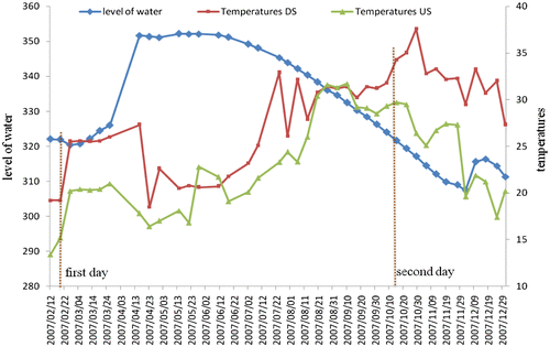
The time intervals used in the successive finite element modelling mentioned in the flowchart of the proposed solution procedure have been gathered as illustrative diagrams in Appendix A of this article. The two red dotted lines in each diagram correspond to two specific days, which are the beginning and the end of the time interval considered for each specific year. These two days were selected in such a way that the reservoir water levels for them are approximately the same.
8. Dam subdivisions
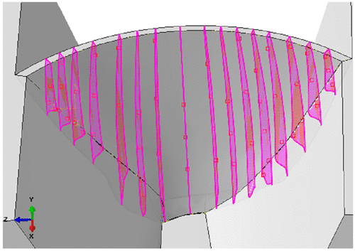
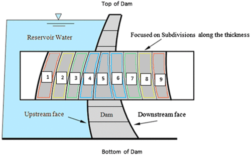
The dam was sub-divided into nine individually homogeneous zones in the thickness direction and into six similar sections along the height of the dam. Along the vertical direction, dam was divided into 17 blocks according to the as-built profile plan of the dam. These blocks are separated from each other by contraction joints (see Figure ). To each of these sub-regions, the previously above-mentioned five unknowns consist of two Young’s modulus, two Poisson’s ratios and one shear modulus were attributed as representative of the long-term concrete damage to be estimated. This subdivision was performed taking into account the Dez Dam geometrical characterizations and construction practice stages as well as optimization of the time consumes for each analysis to be completed. Figure shows a section of the dam with the scheme used for sub-dividing.
9. Dam ABAQUS model
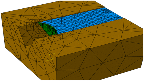
For finite element modelling of the dam, its geologic support and its reservoir, a total number of 14,028 elements were used. For the dam and its support, the C3D4 element type from the element library of the ABAQUS programme was used (Figure ). A relatively large number of 4-nodes tetrahedron elements (C3D4)were used for modelling of dam because that with 8-nodes reduced integration brick elements (C3D8R), the exact modelling of three-dimensional (3D) geometry of the dam and its boundary connection with supports was not accessible. After developing several finite elements (FE) models in ABAQUSv6.13 software, the FE model with the information provided in Table gave the most precise results with a minimum processing time. No instability, divergence and mesh dependency of the results was observed in this final FE model.
Table 2. Element library of the dam–reservoir–foundation model.
10. Results and discussions
During analyses, massive amount of results was generated. For convenience and sake of brevity, those results have been processed and were configured as illustrative figures and tables, which some of the most important of them have been presented in this section. Table represents the final elastic stiffness components obtained for each time interval analysis. Left column in this table indicates the year of the time interval analysis. For each year, the obtained values for out-of-plane Young’s modulus, E H, in-plane Young’s modulus, E V and shear modulus, G H, for the zones 1, 5 and 9 have been recorded. Zones 1, 5 and 9 represent upstream, central and downstream part of the dam, respectively, which was shown before in Figure . These values were obtained in GPa. In addition to elastic modulus, two Poisson’s ratio components, i.e. out-of-plane ratio, v HV, and in-plane ratio v V, have been presented for each year.
Table 3. Long-term elastic stiffness components of the Dez Dam.
Figures and present the obtained long-term variation of the elastic modulus components over time. By comparing these two figures, it can be seen that the out-of-plane elastic modulus, has been reduced more than the in-plane elastic modulus. This is due to a fact that along the thickness direction of the dam, the variety of the environmental conditions is more severe than the vertical direction. Furthermore, it can be understood from these pictures that the reduction of the elastic stiffness components of the dam is larger at the upstream part than the downstream part. This phenomenon is the result of the effect of the humidity fluctuations of the reservoir on the upstream face of the dam which is not exist at the downstream face. From these two diagrams, it can also be observed that the central part of the dam has been kept safe from the deterioration process effects. In fact, this part has been defended by the outer parts of the dam against the environmental actions.
Figure illustrated the reduction of the compressive strength of the mass concrete of the Dez Dam over time. It has been revealed from this figure that this aged concrete material has lost more than 25% of its initial compressive strength during the last 42 years. In addition, it can be seen from this figure that, in the first 10 years of service life of the dam, its compressive strength has not been reduced considerably and this reduction has been accelerated considerably after passing approximately 20 years from the beginning of the service life of the dam. Figures and compare the change of Young’s moduli between top and bottom of the dam in zones 1 and 9 (upstream and downstream faces), respectively. From these two figures, it can be deduced that the reduction in Young’s modulus at top of the dam is greater than the reduction at bottom of the dam. Furthermore, this reduction in upstream face (zone 1) is greater than downstream face (zone 9). The first phenomenon is due to the effect of weight of the dam. In fact, at the bottom of the dam, the concrete is under high confining pressure due to the gravity load and therefore the effects of environment and creep in long-term behaviour of concrete are reduced. The second phenomenon is due to more aggressive climate condition exists on upstream face of the dam, i.e. combination of high degree of humidity and temperature.
11. Main conclusions
A novel inverse method was developed and introduced in this study to assess the long-term behaviour of an old concrete arch dam. The novelty was achieved by combination of thermal inverse method and CDP model of the concrete. This combination was considered in order to enable the authors to evaluate the reduction of compressive strength of the mass concrete of the dam. Furthermore, to capture the change of the strength and stiffness of the dam over time, several thermal inverse analyses were conducted in framework of finite elements method by using the ABAQUS v6.13 standard software and the time interval used in these inverse analyses was limited to one year. At the end of this study, it was revealed that the stiffness reduction of the dam over time in the thickness direction of the dam is greater than the vertical direction. This reduction at upstream face is greater than downstream face of the dam due to more aggressive effects of environmental conditions resulted from combination of high degrees of humidity and high temperatures. Furthermore, the numerical results showed that in the first 10 years of service life of the dam, its compressive strength has not been reduced considerably and this reduction has been accelerated considerably after passing approximately 20 years from the beginning of the service life of the dam. The trends of the change in compressive strength and elastic moduli of the Dez Dam which were obtained in this new attempt of the authors are in complete agreement with the previous numerical model results of the authors [Citation1,2] and the experimental evidence [Citation4]. This new results confirmed that the long-term behaviour of the concrete of arch dams is not a regularized behaviour which obeys from general models such as ‘Fib model code’ [Citation3] or other arch dams’ behaviours [Citation5–8], and is a case to case phenomenon which is dependent of the particular environmental as well as loading histories of the dam. According to studies of Naik, the environment of the Dez Dam is classified as an aggressive condition and under this condition; the strength of the concrete is reduced over time [Citation29]. Furthermore, the results of this study like to the previous studies used this model for modelling the behaviour of arch concrete dams [Citation10–15], demonstrated that the CDP model of the ABAQUS standard software is a powerful numerical material model which can be implemented for prediction of long-term behaviour of arch concrete dams
Disclosure statement
No potential conflict of interest was reported by the authors.
References
- Labibzadeh M , Khajehdezfuli A , Khayat M , et al . Elastic strentgh diagnosis of the Dez concrete arch dam using thermal inverse analysis. J Perform Constr Fac (ASCE). 2014;29(6):04014167-1-04014167-12.
- Labibzadeh M , Khayat M . Heterogeneous and anisotropic long-term concrete damage of the Dez arch dam using thermal inverse analysis. J Inverse Problems Sci Eng. 2015;24(9):1495–1509.
- Fédération International du Béton . Fib model code for concrete structures 2010. Lausanne: Ernst & Sohn; 2013.
- Banian Pey Consultant Engineering Company . Final laboratory and field report on geomechanics and construction materials of the Dez dam- Dam height raising project. Water and Power Supply Authority of Khouzestan Province, Iran; 2012.
- Léger P , Leclerc M . Hydrostatic, temperature, time-displacement model for concrete dams. J Eng Mech. 2007;133(3):267–277.10.1061/(ASCE)0733-9399(2007)133:3(267)
- Léger P , Seydou S . Seasonal thermal displacements of gravity dams located in northern regions. J Perform Constr Fac. 2009;23(3):166–174.10.1061/(ASCE)0887-3828(2009)23:3(166)
- Mata J , de Castro AT , da Costa JS . Time-frequency analysis for concrete dam safety control: Correlation between the daily variation of structural response and air temperature. Eng Struct. 2013;48658–48665.
- Santillán D , Salete E , Toledo M . A methodology for the assessment of the effect of climate change on the thermal-strain–stress behaviour of structures. Eng Struct. 2015;92:123–141.10.1016/j.engstruct.2015.03.001
- Lubliner J , Oliver J , Oller S , et al . A plastic-damage model for concrete. Int. J. Solids Struct. 1989;25(3):299–326.10.1016/0020-7683(89)90050-4
- Ghaedi K , Jameel M , Ibrahim Z , et al . Seismic analysis of Roller Compacted Concrete (RCC) dams considering effect of sizes and shapes of galleries. KSCE J Civil Eng. 2016;20(1):261.10.1007/s12205-015-0538-2
- Ghaedi K , Hejazi F , Ibrahim Z , et al . Flexible foundation effect on seismic analysis of Roller Compacted Concrete (RCC) dams using finite element method. KSCE J Civil Eng. 2017;1–13.
- Zhang S , Wang G , Pang B , Du C . The effects of strong motion duration on the dynamic response and accumulated damage of concrete gravity dams. Soil Dyn Earthq Eng. 2013;45:112–124.10.1016/j.soildyn.2012.11.011
- Zhang S , Wang G , Sa W . Damage evaluation of concrete gravity dams under mainshock–aftershock seismic sequences. Soil Dyn Earthq Eng. 2013;50:16–27.10.1016/j.soildyn.2013.02.021
- Wang G , Wang Y , Lu W , et al . Deterministic 3D seismic damage analysis of Guandi concrete gravity dam: A case study. Eng Struct. 2017;148:263–276.10.1016/j.engstruct.2017.06.060
- Wang G , Zhang S , Zhou C . Correlation between strong motion durations and damage measures of concrete gravity dams. Soil Dyn Earthq Eng. 2015;69:148–162.10.1016/j.soildyn.2014.11.001
- Lee J , Fenves GL . Plastic-damage model for cyclic loading of concrete structures. J Eng Mech. 1998;124(8):829–900.
- Jankowiak T , Lodygowski T . Identification of parameters of concrete damage plasticity constitutive model. J Found Civil Environ Eng. 2005;6:53–69.
- Birtel V , Mark P . Parameterized finite element modeling of RC beam shear failure. ABAQUS User’s Conference. 2006:95–108.
- Kmiecik P , Kamiński M . Modelling of reinforced concrete structures and composite structures with concrete strength degradation taken into consideration. J Arch Civil Mech Eng. 2011;11(3):623–636.10.1016/S1644-9665(12)60105-8
- Labibzadeh M . The numerical simulations of the strengthened RC slabs with CFRPs using standard CDP material model of Abaqus code. Eur J Environ Civil Eng. 2015;19(10):1268–1287.10.1080/19648189.2015.1013637
- Labibzadeh M , Elahifar T . An enhanced finite element model for reinforced concrete two-way slabs strengthened with carbon fiber reinforced polymers. J Struct Eng Int. 2015;25:81–90.10.2749/101686614X14043795570093
- Labibzadeh M , Zakeri M , Shoaib A . A new method for CDP input parameter identification of the ABAQUS software guaranteeing uniqueness and precision. Int J Struct Eng. 2017;8(2):264–284.
- HsuL S , Hsu CTT . Complete stress-strain behavior of high-strength concrete under compression. J Mag Concrete Res. 1994;46(169):301–312.
- Wahalathantri BL , Thambiratnam DP , Chan THT , et al. A material model for flextural crack simulation in reinforced concrete elements using ABAQUS. EddBE Proceedings; 2011, Brisbane. p. 260–264.
- Kupfer H , Hilsdorf HK . Behavior of concrete under biaxial stresses. ACI J. 1969;656–666.
- Nayal R , Rasheed HA . Tension stiffening model for concrete beams reinforced with steel and FRP bars. J Mater Civil Eng. 2006;18(6):831–841.10.1061/(ASCE)0899-1561(2006)18:6(831)
- Enochsson O , Lundqvist J , Täljsten B , et al . CFRP strengthened openings in two-way concrete slabs-An experimental and numerical study. J Constr Build Mater. 2007;21:810–826.10.1016/j.conbuildmat.2006.06.009
- Abaqus, Theory Manual, version 6.11, Dassault systems, 2007.
- Naik TR . Temperature effects on concrete. Philadelphia (PA): American Society for Testing and Materials; 1985.10.1520/STP858-EB
Appendix A
Figure A1. Variations of water level of reservoir and temperature throughout the Year 1965 – blue line denotes water levels of reservoir, red line indicates temperature values at downstream face, green line shows temperature values at upstream face of the Dez Dam and two dotted vertical lines present two days selected for performing thermal inverse analysis.
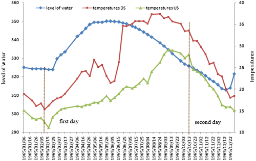
Figure A2. Variations of water level of reservoir and temperature throughout the Year 1970 – blue line denotes water levels of reservoir, red line indicates temperature values at downstream face and green line shows temperature values at upstream face of the Dez Dam and two dotted vertical lines present two days selected for performing thermal inverse analysis.
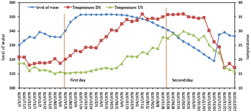
Figure A3. Variations of water level of reservoir and temperature throughout the Year 1973 – blue line denotes water levels of reservoir, red line indicates temperature values at downstream face and green line shows temperature values at upstream face of the Dez Dam and two dotted vertical lines present two days selected for performing thermal inverse analysis.
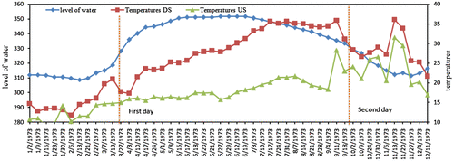
Figure A4. Variations of water level of reservoir and temperature throughout the Year 1976 – blue line denotes water levels of reservoir, red line indicates temperature values at downstream face and green line shows temperature values at upstream face of the Dez Dam and two dotted vertical lines present two days selected for performing thermal inverse analysis.
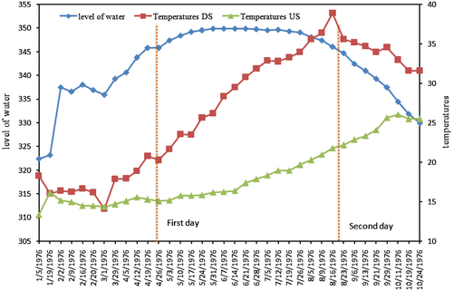
Figure A5. Variations of water level of reservoir and temperature throughout the Year 1980 – blue line denotes water levels of reservoir, red line indicates temperature values at downstream face and green line shows temperature values at upstream face of the Dez Dam and two dotted vertical lines present two days selected for performing thermal inverse analysis.
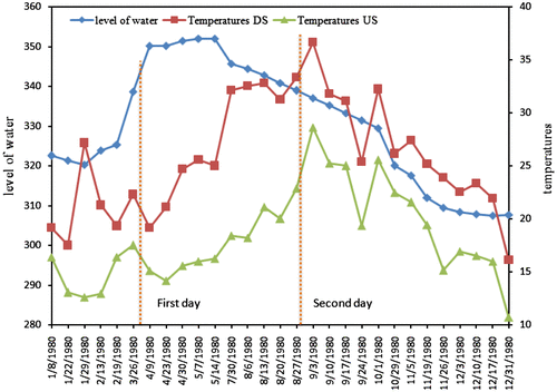
Figure A6. Variations of water level of reservoir and temperature throughout the Year 1987 – blue line denotes water levels of reservoir, red line indicates temperature values at downstream face and green line shows temperature values at upstream face of the Dez Dam and two dotted vertical lines present two days selected for performing thermal inverse analysis.
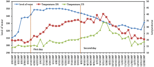
Figure A7. Variations of water level of reservoir and temperature throughout the Year 1991 – blue line denotes water levels of reservoir, red line indicates temperature values at downstream face and green line shows temperature values at upstream face of the Dez Dam and two dotted vertical lines present two days selected for performing thermal inverse analysis.
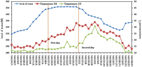
Figure A8. Variations of water level of reservoir and temperature throughout the Year 1995 – blue line denotes water levels of reservoir, red line indicates temperature values at downstream face and green line shows temperature values at upstream face of the Dez Dam and two dotted vertical lines present two days selected for performing thermal inverse analysis.

Figure A9. Variations of water level of reservoir and temperature throughout the Year 1999 – blue line denotes water levels of reservoir, red line indicates temperature values at downstream face and green line shows temperature values at upstream face of the Dez Dam and two dotted vertical lines present two days selected for performing thermal inverse analysis.
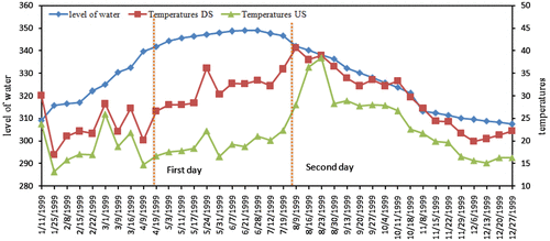
Figure A10. Variations of water level of reservoir and temperature throughout the Year 2001 – blue line denotes water levels of reservoir, red line indicates temperature values at downstream face and green line shows temperature values at upstream face of the Dez Dam and two dotted vertical lines present two days selected for performing thermal inverse analysis.
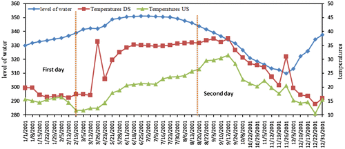
Figure A11. Variations of water level of reservoir and temperature throughout the Year 2005 – blue line denotes water levels of reservoir, red line indicates temperature values at downstream face and green line shows temperature values at upstream face of the Dez Dam and two dotted vertical lines present two days selected for performing thermal inverse analysis.
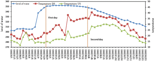
Figure A12. Variations of water level of reservoir and temperature throughout the Year 2007 – blue line denotes water levels of reservoir, red line indicates temperature values at downstream face and green line shows temperature values at upstream face of the Dez Dam and two dotted vertical lines present two days selected for performing thermal inverse analysis.
