
 ?Mathematical formulae have been encoded as MathML and are displayed in this HTML version using MathJax in order to improve their display. Uncheck the box to turn MathJax off. This feature requires Javascript. Click on a formula to zoom.
Abstract
The authors study direct and inverse scattering problems for buried objects in the stratified layered elastic media. It is assumed that a source load is applied on the upper boundary surface, to generate a certain wave field inside the medium. Then we build the solutions to the direct problems through specially constructed Green’s functions for every considered case. Using the known measured amplitude of the upper boundary oscillations over a certain finite-length interval, the inverse problems in a one-mode frequency range are solved. Some numerical examples demonstrate the stability of the proposed algorithm for the formulated inverse problems.
1. Introduction
Recently, there was a need to study layered solids which contain buried objects, to identify the geometries of the objects and to test the methods optimal for detection of such objects. An example of important problem of this kind is given by a black-box detection of damages in the aircrafts using the scattering of the electromagnetic waves. Another example is related to location and size recognition for defects in the elastic layers, for instance, the detection of cavities or voids in structures using ultrasonic waves. There are also other applications, such as mines detection and medical diagnostics. Mathematically, the problems in these fields are reduced to some boundary value problems for elliptic partial differential equations. The Laplace or the Helmholtz equations give the simplest examples of the governing equation for such problems, describing wave processes in elastic and acoustic media.
It is well-known that the boundary value problem for any linear isotropic elastic volume of arbitrary configuration can be reduced to a system of boundary integral equations (BIE), using Green’s function or Green’s tensor; this allows one to evaluate the displacement wave field in the considered domains. The works [Citation1–Citation7] give the governing equations and some efficient techniques for the direct and the inverse diffraction problems in the acoustic and elastic cases. Those methods are applied to simplest geometries of the objects to be identified as well as to simplest geometries of the domain under detection. The application of mathematical and ultrasonic methods to object identification in the elastic media is demonstrated in [Citation8–Citation11]. Very often the input data for the reconstruction in such inverse problems is the measured amplitude of oscillations over a certain part of the outer boundary [Citation5]. The identification method for several cracks simultaneously by the ultrasonic (US) scanning is proposed in [Citation12]. Some applications to the engineering practice of the Ultrasonic (US) impulse propagation in the micro-damaged materials can be found in [Citation13].
The choice of the appropriate mathematical and numerical techniques to identify the geometrical objects, such as cracks, cavities or inclusions, is the subject of many investigations, see [Citation2,Citation14] where the reader can also find further helpful references. The most common approach to solve an inverse problem is its reduction to a system of non-linear operator equations, as a rule, of the first kind. Therefore, generally, the inverse problems are ill-posed, in the sense that small perturbations of the input data may cause large change of the solution. The numerical solution for these operator equations require a certain regularization method [Citation15]. If the geometry of the object under identification is of a particular form defined by a finite number of parameters, like in the cases of linear cracks, spherical or other particular geometries, then the inversion of respective first-kind operators is studied on a finite-dimensional subset. It is known that in this case the inversion is well-posed and numerically stable. The main goal of the present work is to develop a stable numerical algorithm, rather than to prove existence and uniqueness of the formulated problems.
The aim of the present work is to study the inverse problems on reconstruction of buried objects in an isotropic elastic layered medium, based on the known fields measured at a certain part of the free boundary of the medium at a fixed frequency. Using the BIE method, the direct problems are reduced to singular integral equations over the boundary contour of the object. The solution of the BIE system is obtained using the numerical collocation method. Moreover, the problem is reduced to a system of linear algebraic equations with respect to displacement function at the nodes on the object boundary contour. This allows the authors to find the whole field in the medium, in particular, on the upper free surface of the medium. Therefore, the solution of the direct problem, perturbed by a random noise, may be used as the input data for the inverse problem.
The solution to the inverse problems, about identification of a buried object in the stratified elastic media using the input data on the displacement field measured over a certain part of the free surface of the medium is constructed in two steps: in the first step, we construct the dynamic displacement field in the single layer or in the case of two layers, by the known source load on the upper surface of the medium. While in the second step and based on this latter information, the inverse problem for identification of the geometry of the buried object and its location is solved. The consideration is restricted by elliptic voids, in the one-mode frequency range. This predetermines a finite-dimensional inversion, since any elliptic object is defined by no more that five geometric parameters. More specifically, the inverse problem for domain’s geometry described by a finite number of parameters can directly be reduced to a linearization of the well-posed initial system of non-linear equations, which automatically leads to a stable identification algorithm.
2. The governing equations for a buried object in the case of single- and double-layered elastic medium
2.1. Problem1
Here, we formulate the anti-plane (SH) problem of harmonic oscillations of an isotropic elastic layer containing a void. Let us consider the homogeneous elastic layer of thickness h containing a buried void with a smooth contour l, see Figure . Let us choose the Cartesian coordinates
such that the horizontal axis coincides with the lower fixed boundary
, and the upper free boundary
of the layer is loaded by a point force applied at
and harmonically oscillating with the circular frequency
.
Figure 1. A buried object in the single-layered elastic medium.
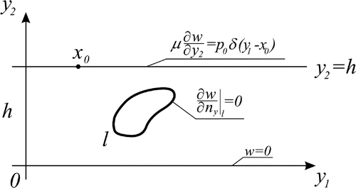
In the case of anti-plane (SH) deformation, the only nontrivial component of the displacement vector field is . The only nontrivial components of the stress tensor are:
,
, where
is the shear elastic modulus. Then the problem is reduced to the following boundary value Problem 1, see [Citation1]:
(2.1)
(2.1)
(2.2)
(2.2)
where is the Laplace operator, k is the wave number, c is the transverse wave speed,
is the mass density,
is the amplitude of the outer applied oscillating point force. To complete the formulation, it is necessary to add a radiation condition at infinity.
If the geometry of the contour l is known then the problem is a standard direct diffraction problem. If it is solved by any method, the basic wave field can be determined at any observation point, including the upper free boundary surface
. If the void’s boundary contour l is unknown then one can formulate respective inverse problem to identify the geometry of the contour by knowing, say the amplitude of the oscillations over a finite interval of the free surface
. The latter can be taken as an input data from the results of the ‘measurements’ obtained from some natural or numerical experiments. In our theoretical treatment such an input data may be obtained from the numerical solution of respective direct problem subjected to a certain perturbation by a random noise.
Further, let us apply a standard technique of the potential theory. If one constructs Green’s function ,
, inside the layer
(2.3)
(2.3)
which satisfies, similarly to the two first boundary conditions (Equation2.2(2.2)
(2.2) ), the Neumann homogeneous condition over the upper face of the layer
and the Dirichlet homogeneous condition over the lower face of the layer
:
(2.4)
(2.4)
then a classical result of the potential theory claims that [Citation16](2.5)
(2.5)
for any point inside the layer located outside contour l . The superscript (1) here above Green’s function
indicates that the latter is related to Problem 1,
is the outer unit normal to the contour
, which itself is a union of contour l and the two faces of the layer:
. Obviously, the integral over the lower layer’s face is trivial, since both the quantities w and
are trivial over this horizontal axis, due to their boundary conditions. Analogously, the integral in (Equation2.5
(2.5)
(2.5) ) taken over the upper layer’s face
can also be calculated explicitly, using respective boundary conditions for quantities
and
. As a result, Equation (Equation2.5
(2.5)
(2.5) ) can be rewritten in the following form:
(2.6)
(2.6)
where f is the wave field in the homogeneous layer, free of any buried object. Note that in Equation (Equation2.6
(2.6)
(2.6) ) is the unit normal vector chosen outer to contour l. Now, one can easily deduce from Equation (Equation2.6
(2.6)
(2.6) ) the basic boundary integral equation (BIE) of Problem 1, if one moves the point
to the boundary l :
, from outside. Then, according to the properties of the potential of double layer [Citation2], one deduces from Equation (Equation2.6
(2.6)
(2.6) ) the following BIE:
(2.7)
(2.7)
It should be noted that generally the kernels in some formulations of BIEs may possess certain singularities [Citation2]. However, for the anti-plane problem, it is known that in the case of smooth boundary line the Neumann boundary value problem is reduced to the second-kind integral equation whose kernel contains no singularity as . It can be proved that in this case the limiting value of the kernel is expressed in terms of curvature of the boundary curve which is always finite if the contour is smooth.
2.2. Problem 2
Let us consider the Problem 2 about harmonic oscillations of two homogeneous elastic layers of thickness , respectively, see Figure . The cavity with a smooth contour l is located in the upper layer (I), while the lower layer (II) consists of a different elastic material. Assume that the oscillations in the media is caused again, like in the Problem 1, by a source load applied at the upper surface
of the first layer, i.e. at a certain point
. It should be noted that the case when the defect is located in the lower layer (II) can be studied by analogy.
Figure 2. A buried object in the upper layer of the double-layered elastic medium.
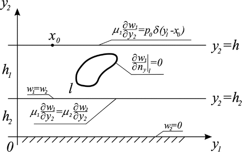
The Problem 2 at hand is mathematically governed by the following equations. For the upper layer (I), it can be written as follows:(2.8)
(2.8)
For the lower layer (II) one writes:(2.9)
(2.9)
Besides, the boundary conditions on the interface should be added since the displacement and the stress fields are continuous when crossing this interface line:
(2.10)
(2.10)
In the same way as in Problem 1, a specific Green’s function can be introduced for this boundary value Problem 2 ():
(2.11)
(2.11)
Green’s function in the upper layer (I) is defined as follows: (2.12a)
(2.12a)
while for the lower layer:(2.12b)
(2.12b) with the same boundary conditions of the continuity on the interface line
:
(2.13)
(2.13)
Using the constructed Green’s function, it can be proved that the following representation of the potential theory, like in (Equation2.6(2.6)
(2.6) ):
(2.14)
(2.14)
is valid at arbitrary point in the upper layer, outside contour l. The standard approach leads again to the basic BIE in this Problem 2, analogous to Equation (Equation2.7
(2.7)
(2.7) ) in Problem 1:
(2.15)
(2.15)
2.3. Problem 3
Further, let us consider the anti-plane Problem 3 about harmonic oscillations of two homogeneous elastic layers of thickness and
, respectively. On the interface boundary surface
there is located a void whose smooth boundary contour
is free of any load, see Figure . It is assumed that the upper part of the contour,
is fully located in the first layer (I), and the lower part
is fully located in the second layer (II). Therefore, the boundary value problem 3 can be written for each layer as follows:
Figure 3. A buried object on the interface of the double-layered elastic medium.
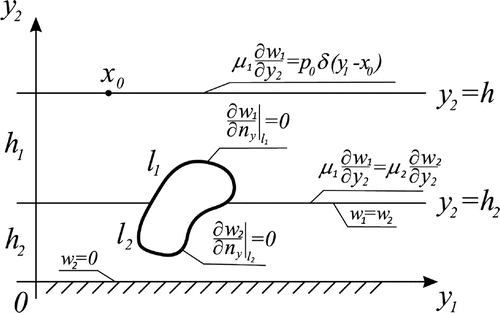
For the upper layer (I): (2.16a)
(2.16a)
For the lower layer (II):(2.16b)
(2.16b)
To complete the formulation of the Problem 3, one should add the boundary conditions (Equation2.10(2.10)
(2.10) ) on the internal interface
, outside the buried object.
To solve the formulated boundary value Problem 3, we should build Green’s tensor in the two-layered medium. The components of Green’s tensor can be presented as follows:(2.17)
(2.17)
where domain contains all points of the first layer outside contour
, and domain
is analogous in the second layer.
Thus, the pair of the boundary value problems can be formulated here: (2.18a)
(2.18a)
and(2.18b)
(2.18b)
The boundary conditions on the internal interface, are the conditions of continuity for the component of Green’s displacements tensor and their corresponding components of shearing stress that:
(2.19)
(2.19)
By analogy to Problems 1 and 2, if Green’s tensor is constructed for the present Problem 3, the standard approach of the potential theory reduces this problem to the system of BIEs: (2.20a) & (2.20b)
(2.20a) & (2.20b)
In order to solve the direct Problems 1–3, one should build Green’s functions for the corresponding boundary value problems. The next section is devoted to construct Green’s functions and Green’s tensors for elastic layered medium in an explicit form.
3. Green’s functions for Problems 1–3
3.1. Problem 1
Let us start with Problem 1 for the single layer; this means to solve the boundary value problem (Equation2.3(2.3)
(2.3) )–(Equation2.4
(2.4)
(2.4) ).
The solution to Equation (Equation2.3(2.3)
(2.3) ), for any fixed point
inside the layer, may be obtained using the integral Fourier transform along the horizontal axis
:
(3.1)
(3.1)
Then, using the classical property of Dirac’s delta function:, the general solution to homogeneous equation and a particular solution of the full equation, one deduces:
(3.2)
(3.2)
the quantities should be determined from the boundary conditions (Equation2.4
(2.4)
(2.4) ). The solution is constructed in the following form [Citation14]:
(3.3a) & (3.3b)
(3.3a) & (3.3b) Notice that function
is meromorphic with respect to s. The (simple) poles of function
coincide with the zeros of the denominator:
(3.4)
(3.4)
It is clear that for sufficiently low frequencies (small values of the wave number k) real-valued poles are absent, then all singularities of the integrand in (Equation3.3a(3.3a) & (3.3b)
(3.3a) & (3.3b) ) are located outside the contour of integration. This is the case we call ‘the one-mode regime’. However, with frequency increasing more and more poles cross the real axis
. It can be proved that Sommerfeld’s principle of radiation condition predetermines that the integration path should bend a little around the positive poles from below and the negative ones from above. In practice, in the demonstrated examples of object’s identification, see Section 6 below, the value of the wave number is chosen at the top part of the considered one-mode frequency range.
By applying the Jordan lemma [Citation17], the integral (Equation3.3(3.3a) & (3.3b)
(3.3a) & (3.3b) ) can be calculated as a series by residues at simple poles:
(3.5)
(3.5)
3.2. Problem 2
Let us pass to the Green’s functions for Problem 2, which is to be determined as a solution of the boundary value problem (Equation2.11(2.11)
(2.11) )–(Equation2.13
(2.13)
(2.13) ). By analogy to Problem 1 we apply the Fourier transform along variable
, which reduces the governing equations to a pair of ordinary differential equations, with respect to variable
whose solution in Fourier images is:
(3.6)
(3.6)
Then the full representation for the Green’s functions under consideration is given by the inverse Fourier transform, as follows:(3.7)
(3.7)
The substitution of representations (Equation3.6(3.6)
(3.6) ) into the corresponding boundary conditions (Equation2.12
(2.12a)
(2.12a) ), (Equation2.13
(2.13)
(2.13) ) leads to a
SLAE for the four unknown quantities
. Its solution determines functions
in the following form (
):
(3.8a) & (3.8b)
(3.8a) & (3.8b)
Obviously, Green’s functions for Problem 2 should degenerate to the one in the Problem 1. One can easily control that the two following limiting cases take place:
| (i) | If the thickness of the second layer tends to zero then | ||||
| (ii) | If the materials of the two elastic layers are identical then | ||||
3.3. Problem 3
At last, let us develop the Green’s tensor for Problem 3. By writing all four functions in terms of the inverse Fourier transform(3.10)
(3.10)
it can be easily seen, on the basis of the governing equations, that the first two of them coincide with respective functions of Problem 2. Namely, one obtains: ,
. The other two components are determined in the following way:
(3.11a) & (3.11b)
(3.11a) & (3.11b)
4. Numerical treatment of the BIE
In order to solve the direct diffraction Problems 1–3 formulated above, one should solve integral Equations (Equation2.7(2.7)
(2.7) ), (Equation2.15
(2.15)
(2.15) ), (Equation2.20
(2.20a) & (2.20b)
(2.20a) & (2.20b) ), respectively. Let us apply a collocation numerical technique in its simplest form. This implies to split the full closed contour l to N small chords of a polyline, then to apply a simple quadrature formula with a constant integrand over each small chord
of length
. Note that point
runs over the same set of nodes as point
:
,
. As noticed above, the arising BIEs of the second kind in the case of smooth boundary contour l have no singularity as
, hence the collocation method can be treated like in the regular cases with continuous kernels [Citation18]. With the simplest treatment it is demonstrated here for Problem 1, Equation (Equation2.7
(2.7)
(2.7) ):
(4.1)
(4.1)
where . The case of Equation (Equation2.15
(2.15)
(2.15) ), as well as the system of integral Equations (Equation2.20
(2.20a) & (2.20b)
(2.20a) & (2.20b) ), can be treated by analogy.
The only unclear question here is connected with the known property that a vertex of an angle, where two different elastic materials meet, may contain a singularity of the stress. In fact, this may happen in Problem 3 at two points where the boundary curve l intersects the interface line , the situation which is locally like a vertex of the angle mentioned above.
Let us show that in the anti-plane problem this singularity is certainly absent at least in the case when the boundary contour l is locally orthogonal to the interface line . In this case, we have two quarter-planes joined by one face, each of them with the second face free of load. The proof is based on the property that dynamic elastic problems possess the same singularities as the respective static problems. In the static case the governing equation is the Laplace equation, which should hold inside the upper (I) and the lower (II) quarter-plane. In the local polar coordinate system
,
for domain (II) and
for domain (I), this means:
(4.2)
(4.2)
Let us seek the solution to the ‘pair-of-quarter-planes’ problem in the following form:(4.3)
(4.3)
with a certain possible singularity as , in the case if
is not a positive integer. Here, due to a symmetry (the opening angles in both the quarter-planes are equal to
), we set equal singularity power:
. The substitution of (Equation3.3
(3.3a) & (3.3b)
(3.3a) & (3.3b) ) into (Equation3.2
(3.2)
(3.2) ) leads to the ordinary differential equations
, whose general solution is:
(4.4)
(4.4)
Now, the boundary conditions on the interface , as well as over free side surfaces,
;
, lead to a
homogeneous SLAE for the unknown coefficients
. Since we seek a non-trivial solution of this system, its determinant should be trivial, which results in the simple transcendental equation:
. Therefore, it is clear that appropriate values of this transcendental equation are
, since negative integers break the finite-energy condition. It follows from the obtained result that there is no singularity of the solution for such a simple geometry.
It should be noted that the case of ‘no singularity’ studied above is automatically attained if the centre of the elliptic object is located on the interface line , since in this case the tangent lines at the two intersection points are locally orthogonal to the interface, i.e. just the case studied above in this section.
All examples presented below are related to the outer harmonic force of a unit amplitude . Figure demonstrates an example of the solution to the direct Problem 1 for the considered single-layered medium, which contains an elliptic cavity as a buried object. This is calculated for various inclination angles
between the principal axis of the ellipses and the horizontal axis
. The presented diagrams are related to the displacement field over the upper free surface of the layer:
. The variation of the mesh dimension from
to
shows insignificant variation of the diagrams, invisible in the figure. Similar diagrams for a round object are presented in Figure , for various horizontal coordinates of the object’s central point, quantity
. Figures and show in the direct Problem 3 the diagram of the displacement over the boundary contour l for an elliptic object of a number of different aspect ratio. This is plotted separately for the upper part of contour l, which is located fully in the upper layer (I), and for the lower part of contour l, which is fully located in the lower layer (II). The relation of elastic parameters between the two elastic media is the same as copper (medium I) and steel (medium II).
Figure 4. Direct Problem 1, ,
,
. The displacement over the upper surface, elliptic void: semi-axes
, central point
,
is the slope of the principal axis with respect to
.
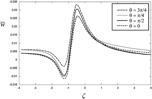
Figure 5. Direct Problem 1, ,
,
. The displacement over the upper surface, round void:
,
.
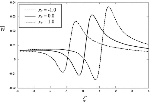
Figure 6. Direct Problem 3, ,
,
,
,
. The displacement
over the upper part of the boundary contour l versus polar angle of the current boundary point on the interval
, elliptic void: semi-axes
, central point
.
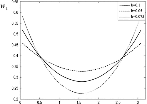
Figure 7. Direct Problem 3, ,
,
,
,
. The displacement
over the lower part of the boundary contour l versus polar angle of the current boundary point on the interval
, elliptic void: semi-axes
, central point
.
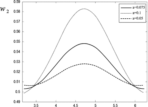
Figure 8. Direct Problem 1, ,
,
,
. The displacement w over the boundary line versus polar angle, three different rectangular voids with filleted corners:
.
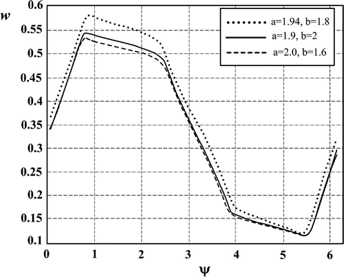
Additionally, in order to demonstrate the possibilities of the proposed method, we plot in Figure the displacement w at the points of the boundary contour l, direct problem 1, for three different rectangular voids with filleted corners. The defining equation is as follows:(4.5)
(4.5)
5. Formulation of the inverse Problems 1–3
The inverse problem for any respective direct Problem 1–3 is to restore, or to identify, the location and the geometry of the buried object, under assumption that this is of an elliptic form. The formulation is as follows. Under condition of the harmonic oscillation of the layered medium generated by the outer point force applied over the upper free surface at point
, the information about the amplitude of the free surface oscillations, function
is known at a fixed frequency, over a certain interval
. It is assumed that
. In order to solve the inverse problem, the input data, function
, is taken from the solution of the respective direct problem, perturbed by a random noise of a certain amplitude. As can be seen from the previous sections, function
is easily calculated for any problem if respective BIEs are solved numerically by the collocation method. More precisely,
In Problem 1:(5.1)
(5.1)
In Problem 2:(5.2)
(5.2)
In Problem 3:(5.3)
(5.3)
Here the terms f in Equations (Equation2.6(2.6)
(2.6) ) and (Equation2.14
(2.14)
(2.14) ), as well as terms
in Equation (Equation2.20
(2.20a) & (2.20b)
(2.20a) & (2.20b) ), all have been omitted. This means that the amplitude of the free-surface oscillations, function
is taken in its relative form, when compared with the analogous amplitude for the medium without any buried object.
The inverse problem on object’s image identification is to find contour l from Equations (Equation5.1(5.1)
(5.1) )–(Equation5.3
(5.3)
(5.3) ), if the input data i.e. function
is known, at least with a certain random noise, over a chosen interval
. It should be noted that not only contour l is unknown in Equations (Equation5.1
(5.1)
(5.1) )–(Equation5.3
(5.3)
(5.3) ) but also functions
are unknown on the unknown contour l. The so-formulated mathematically inverse problem is obviously non-linear with respect to a constitutive equation of this contour l. Generally, this problem is nonlinear and ill-posed. However, as indicated above, in the case of elliptic object this problem is solved in a finite-dimensional space, hence this becomes well-posed. The questions of existence and uniqueness are out of the scope of the present study.
Let us rewrite the basic BIEs (Equation2.7(2.7)
(2.7) ), (Equation2.15
(2.15)
(2.15) ), (Equation2.20
(2.20a) & (2.20b)
(2.20a) & (2.20b) ), for any direct Problem 1 – 3, symbolically as an operator equation:
(5.4)
(5.4)
where in Problem 1: ; in Problem 2:
; in Problem 3:
. The numerical collocation technique, developed in the previous section, permits efficient solution of respective BIEs written in a certain discrete form; this implies the numerical inversion of operator
, if the boundary contour l of the void is known:
(5.5)
(5.5)
Here we have indicated explicitly that the inverse operator depends upon the geometry of the elliptic contour l, which is defined at most by the five geometric parameters: two Cartesian coordinates of its center
, the lengths of its two semi-axes a and b, and the slope angle
between the principal axis and the horizontal coordinate axis
.
Further, let us rewrite symbolically relations (Equation5.1(5.1)
(5.1) )–(Equation5.3
(5.3)
(5.3) ) in a unified form, as a certain operator relation having the input data, function
, in the right-hand side:
(5.6)
(5.6)
where again operator depends on the geometry of contour l which is equivalent to its dependence again upon the five parameters
. By substitution of (Equation5.5
(5.5)
(5.5) ) into (Equation5.6
(5.6)
(5.6) ), one obtains:
(5.7)
(5.7)
In Equation (Equation5.7(5.7)
(5.7) ) all included functions and operators are known. The only unknown quantities are five geometric parameters defining the geometry of the object’s boundary curve l. If the amplitude of vibrations of the upper surface (
) is known exactly as a solution to the direct problem, then the solution of the operator Equation (Equation5.7
(5.7)
(5.7) ) should coincide with the real contour l which is used for the direct problem. However, the construction of a stable numerical algorithm, to determine five parameters
from operator Equation (Equation5.7
(5.7)
(5.7) ) is not simple, is one does not known a priori the contour l of the direct problem. This question is much more complex in the case when the input data, function
is extracted from the solution of the respective direct problem, further perturbed by a random noise. Therefore, the proposed algorithm for object identification should be stable with respect to small perturbations of the input data.
6. Numerical algorithm and examples of the reconstruction of elliptical voids
Let us assume that function in Equation (Equation5.7
(5.7)
(5.7) ) is known in a discrete set of nodes
. Then Equation (Equation5.7
(5.7)
(5.7) ) in the discrete form reads as follows:
(6.1)
(6.1)
The proposed numerical algorithm is based on a minimization of the discrepancy functional [Citation19] of Equation (Equation6.1
(6.1)
(6.1) ):
(6.2)
(6.2)
which in the non-linear problem is generally non-quadratic.
It should be noted that, in spite of the formulated inverse problems are theoretically finite-dimensional, hence well-posed, in the numerical implementation this may lead to a practical instability in the case of the noisy input data. By this reason, we used in our numerical experiments the steepest descent iteration method which is known to provide a sort of iterative regularization [Citation20]. The method applied thus brings an additional stability to the identification algorithm proposed.
Some examples of the reconstruction are demonstrated here in tables. For all examples, we used , to form the array of the input data, such that
,
. It should be noted that for all tables we choose the following criterion, to stop the iteration process on the nth step:
.
Table 1. Examples of the reconstruction, Problem 1: ,
,
,
, Noise level = 0 %, bold font – exact geometry.
Table reflects some identification results for Problem 1. This is principally aimed at the study of identification precision versus the length of the sensing interval .
Table demonstrates object identification for Problem 2. Here only horizontal principal axis of the elliptic object has been used in our numerical experiments. The number of the geometrical parameters to be reconstructed here is four since in this case the slope angle is excluded from the array of standard five parameters.
Table 2. Examples of the reconstruction, Problem 2: ,
,
,
,
, bold font – exact geometry.
Table 3. Examples of the reconstruction, Problem 3: ,
,
,
,
,
, bold font – exact geometry.
Table demonstrates the precision of the object’s image reconstruction for Problem 3. Only three geometrical parameters are to be restored from the list of five parameters in the general case. In fact, the centre of the void is placed just on the interface straight line , hence
and
in this case.
Table 4. Examples of the reconstruction with different positions of void’s central point, Problem 1, a rectangular void approximated by an elliptic defect: ,
,
,
,
,
,
,
,
, Noise level = 10 %, bold font – exact configuration.
Moreover, we have performed a numerical experiment on reconstruction of a non-elliptic object, more exactly – a rectangular void with filleted corners, by approximating it by an ellipse, see Table . For this aim, we first have solved the direct problem for the exact object (rectangle) as shown in Figure . The so obtained input data, the calculated displacement over the upper surface of the layer, is used to solve the inverse problem in the class of elliptic defects by the algorithm presented above. As can be seen from Table , the relative error in the identification of defect’s area does not exceed 4%. The maximum relative error in the identification of the central point coordinates is around 6%.
At last, let us compare our results with some others known in literature. The authors could not find any published paper, for a direct comparison. However, Pompei et al. [Citation21] solve a static anti-plane problem for identification of elliptic voids in an elastic half-space. Their results can be obtained from the present work, Problem 1, as a particular case when thickness h of our layer tends to infinity: , and wave number k becomes very small:
. Besides, we should reverse the direction of the vertical axis
to be directed downward. This requires to modify slightly the boundary conditions, namely, the harmonic load to act on the upper boundary
, and the lower boundary
to be fixed. With so doing, the representation for Green’s function may directly be taken from [Citation14], chapter 3. The only change is that function
in Equation (Equation2.6
(2.6)
(2.6) ) should be taken with opposite sign.
The comparison of our results with [Citation21], on a particular example is demonstrated in Table .
Table 5. Comparison with [21], Problem 1: ,
,
, Noise level = 0 %,
.
7. Conclusions
The basic results and the principal conclusions are listed here below:
| (1) | The paper proposes some efficient methods to solve the anti-plane dynamic problem of the linear isotropic elasticity theory, for layered elastic media with a buried object located inside the media. | ||||
| (2) | On the basis of the constructed Greens’ functions, the direct problem is reduced to a single BIE or to a system of BIEs, holding over the boundary contour of the buried object. | ||||
| (3) | There is developed an efficient numerical algorithm for the system of integral equations on the basic of collocation method, which solves the formulated direct diffraction problems. | ||||
| (4) | There is developed a numerical algorithm, to solve the inverse object identification problems in the layered media, which is founded on the minimization of the discrepancy functional. Some examples demonstrating the solution to the direct and the inverse problems are presented as diagrams and tables. The solution of the inverse problems is adapted to the case of elliptical voids. | ||||
| (5) | The precision of the reconstruction weakly depends on the noise level. This is much more sensitive to the geometry of the object, as well as to the values of other geometric parameters, such as the length of the interval | ||||
| (6) | It is clearly seen from Table that object’s identification becomes more precise if the interval of the ‘measurement’ | ||||
| (7) | Table confirms that the elongated objects are identified with a less precision that is quite natural from the heuristic point of view. | ||||
| (8) | Table demonstrates that the identification with less number of parameters (only three geometrical parameters) is performed with a better precision than in the general case of five parameters. | ||||
| (9) | Table shows a good precision in the identification of the defects of non-elliptic shapes. It is very important that the area of the defect is identified precisely. This fact, of course, is of a great practical significance in the ultrasonic NDT. | ||||
| (10) | Table demonstrates an acceptable precision when our dynamic results of the identification in the layer are compared with a static problem in the half-plane. This comparison is admissible for low frequencies and deep layer. It is also interesting that some results of the reconstruction in Table , which initially seem to be far from the true geometry, in fact describe a void very close to the exact geometry. The difference becomes inessential there since the reconstructed object is turned through right angle, and simultaneously the bigger axis of the ellipse becomes its smaller one. | ||||
Disclosure statement
No potential conflict of interest was reported by the authors.
Additional information
Funding
References
- Achenbach JD . Wave propagation in elastic solids. Amsterdam: North-Holland; 1973.
- Colton D , Kress R . Inverse acoustic and electromagnetic scattering theory. Berlin: Springer-Verlag; 1992.
- Bonnet M , Constantinescu A . Inverse problems in elasticity. Inverse Probl. 2005;21:1–50.
- Colton D , Kress R . Using fundamental solutions in inverse scattering. Inverse Probl. 2006;22:49–66.
- Ikehata M . Reconstruction of obstacle from boundary measurements. Wave Motion. 1999;30:205–223.
- Bui HD , Constantinescu A , Maigre H . Numerical identification of linear cracks in 2D elastodynamics using the instantaneous reciprocity gap. Inverse Probl. 2004;20:993–1001.
- Trong DD , Ang DD . Identification of cavities in a three dimensional elastic body. Z Angew Math Mech. 2004;23:407–422.
- Vorovich II , Boyev NV , Sumbatyan MA . Reconstruction of the obstacle shape in acoustic medium under ultrasonic scanning. Inverse Probl Eng. 2001;9:315–337.
- Boyev NV , Vatulyan AO , Sumbatyan MA . Reconstruction of the contour of obstacles from the scattered acoustic field in high frequency range. Acoust Phys. 1997;43:391–394.
- Scalia A , Sumbatyan MA . On efficient quantitative analysis in real-time ultrasonic detection of cracks. Ultrasonics. 1999;37:239–245.
- Brigante M , Sumbatyan MA . An efficient numerical algorithm for crack reconstruction in elastic media by the circular US scanning. Inverse Probl Sci Eng. 2010;18:361–379.
- Brigante M , Sumbatyan MA . Reconstruction of crack clusters in the rectangular domain by Ultrasonic waves. Res Nondestructive Eval. 2010;21:193–212.
- Sumbatyan MA , Brigante M . Analysis of strength and wave velocity for micro-damaged elastic media. Eng Fract Mech. 2015;145:43–53.
- Sumbatyan MA , Scalia A . Equations of mathematical diffraction theory. Boca Raton (FL): CRC Press; 2005.
- Engl HW , Hanke M , Neubauer A . Regularization of inverse problems. Dordrecht: Kluwer; 1996.
- Jones DS . The theory of electromagnetism. London: Macmillan; 1964.
- Markushevich AI . Theory of functions of a complex variable. New York (NY): American Mathematical Society; 2005.
- Wazwaz A-M . Linear and nonlinear integral equations. Methods and applications. Berlin, Heidelberg: Springer; 2011.
- Gill PE , Murray W , Wright MH . Practical optimization. London: Academic Press; 1981.
- Kantorovich LV , Akilov GP . Functional analysis. New York (NY): Pergamon Press; 1982.
- Pompei A , Rigano A , Sumbatyan MA . Reconstruction of elliptic voids in the elastic half-space: anti-plane problem. Far East J Appl Math. 2006;25:137–158.