 ?Mathematical formulae have been encoded as MathML and are displayed in this HTML version using MathJax in order to improve their display. Uncheck the box to turn MathJax off. This feature requires Javascript. Click on a formula to zoom.
ABSTRACT
This paper develops and presents a technique on the identification of the damage location and depth in a beam using a frequency contour method. Unlike the frequency contour methods presented in the literature, the one presented in this work does not require neither the solving of the governing differential equation analytically to obtain the contour lines, nor the calculation of the frequencies by varying all damage severities and locations in order to use an inverse problem to plot the contours. In other words, the detection method does not require the modelling of the damage. In this work, a contour line is plotted using only the value of the changes in the measured natural frequencies and the vectors of the curvature mode shapes of the intact structure which can be calculated numerically or can be derived from the measured mode shapes. In order to verify the practical applicability of the developed theoretical method, a numerical simulation and an experimental framework on cantilever beam have been designed and the results confirm the applicability of the developed method in the real applications.
AMS SUBJECT CLASSIFICATIONS:
1. Introduction
In the last few decades, damage detection appeared as one of the main fields of research integrating many interdisciplinary fields to ensure structure safety. The damage produces a local change in stiffness, which products a discontinuity in the mode shape, reduces frequency and increases damping. These changes in the dynamic properties (modal parameters) can be measured and leads to the identification of the damage location and severity. Based on these changes, many engineers and scientists have devoted their time and efforts towards developing a different method for damage detection. In [Citation1–7], the authors reviewed articles on the damage detection through the dynamic properties.
The damping is the least applied modal parameter for the damage detection, due to the difficulty involved in traditional measurement set-up. Otherwise, the smart sensing technologies such as piezoelectric sensors [Citation8] and optical fibre sensor [Citation9,10] have made the acquisition to obtain damping. Cao et al. [Citation11] gave a review of structural damage detection using damping.
Another modal parameter used in the damage detection is the mode shape. Two of the first works which are the most famous ones are the modal assurance criteria (MAC) by West [Citation12] and the coordinate modal assurance criterion (COMAC) by Lieven and Ewins [Citation13], in which the damage detection is based on the correlation between the mode shapes of a damaged and an intact structure. The criterions take a value of 1 for an exact pattern match and 0 if the pattern is uncorrelated. Based on that, several criteria have been presented, including ‘Partial Modal Analysis Criterion’ (PMAC) by Heylen [Citation14], ‘Modal Assurance Criterion Square Root’ (MACSR) by O’Callahan [Citation15] and ‘Scaled Modal Assurance Criterion’ (SMAC) by Brechlin et al. [Citation16]. Allemang [Citation17] reviewed different assurance criteria. Abdo and Hori [Citation18] used the first derivative of mode shapes (mode shapes slope) and concluded that the mode shape slope has a good result in locating multiple damages with different sizes in a structure compared to the mode shape. Pandey et al. [Citation19] showed that the curvature mode shape (second derivative of mode shape) is more sensitive to the damage because it amplifies the effects of the damage. Roy and Ray [Citation20] established mathematical expression based on a perturbation approach to demonstrate that the changes in the mode shape and its derivatives are related to the damage location. The developed technique of the damage location is applied in shear building and steel moment-resisting frame. Gladwell and Morassi [Citation21] studied the effect of damage on the mode shape nodes and showed that the nodes move towards the damage. At the end, they concluded that the damage can be located by finding the nodes which move towards each other. Xiang et al. [Citation22] suggested that the mode shapes (or their derivatives) are efficient parameters to detect damage in static structures, but they cannot be directly extended to operating structures. So, the authors proposed a new method based on operating deflection shape (ODS), which is a summation of all the mode shapes of the structure. The method is applied for a plate structure which is excited by a harmonic force.
In some cases, the data of the intact structure cannot be obtained easily. Some researchers investigated in the damage detection with the use of only the mode shape of the damaged structure without the knowledge of the intact structure model. The authors in [Citation23–27] demonstrated that the mode shape of the intact structure and its derivatives have a smooth surface and can be approximated by a polynomial. So, the damage can be detected by comparing the measured mode shape with the smoothed polynomial instead of the mode shape of the intact structure. Since the damage produces a local discontinuity in the mode shape, the wavelet transform appears as an attractive approach to detect this discontinuity and to locate the damage without the knowledge of the intact structure model [Citation28–32]. Algaba et al. [Citation33] and Solis et al. [Citation34] proposed the wavelet analysis to remove the noise in the measured mode shape which can be interpreted as damage. Cao et al. [Citation35] indicated that the drawback of deriving the mode shape is the fact that it amplifies the noise and proposed an approach that combines a Teager energy operator and a wavelet transform to improve the curvature mode shape and decrease the sensitivity to noise. Kim and Melhem [Citation36] reviewed papers conducted on damage detection by wavelet analysis. In order to detect the damage with small severity, the authors in [Citation37–39] propose to measure the modal data using scanning laser Doppler vibrometer to reduce the noise and avoid the weight accelerometer which slightly modifies the structure.
The use of the mode shapes (or their derivative) alone is limited to the localization level. In order to quantify the damage, hybrid methods using both the frequencies and modes shapes (or their derivatives) are proposed in literatures. Xiang et al. [Citation40] suggested a simple two-steps method using both the natural frequencies and the mode shapes curvatures. First, wavelet transform is used to localize the damage location from mode shapes curvatures. Then, particle swarm optimization is proposed to quantify the damage depth using a relationship between few natural frequencies and the damage severity. The proposed method was applied in beams structures and the results show that the method can be used to localize and quantify the damage with precise. Later, the authors in Xiang et al. [Citation41] extended the method for conical shells, and then for the plate structure in Xiang et al. [Citation42] and Jiang et al. [Citation43].
However, the measurement of a mode shape requires a number of measurements at each of the slices of the structures. Since frequency measurements can be cheaply be acquired, the use of the frequency changes becomes the most inexpensive structural assessment technique. Salawu [Citation44] reviewed 65 articles in the damage detection through changes in the natural frequencies. Cawly and Adam [Citation45] demonstrated that the ratio of frequency changes in two modes is a function of only the damage location, and proposed a method to locate the damage by comparing the theoretical frequency shifts due to damage at selected location with measured ones. The authors in [Citation46–48] extended the Modal Assurance Criterion (MAC) given by West [Citation12], using the natural frequencies instead of the mode shape. The criterion is termed a Multiple Damage Location Assurance Criterion (MDLAC), which is defined as a statistical correlation between the changes in the frequency predicted analytically and the changes in the measured frequency. Gillich and Praisach [Citation49] showed that the appearance of the curve formed by the natural frequency shifts does not change as function of damage depth but changes only as function of damage location. Therefore, the curves of the natural frequency shifts are plotted for each damage location and are compared with the measured ones, and those which most resemble indicate the location of the damage. Gillich et al. [Citation50,51] showed the relationship between the frequency changes and the normalized square mode shape curvature, and developed a correlation method where the set of values used in the correlation are dependent only on the damage location. Recently, Dahak et al. [Citation52] showed that if the natural frequency of one of the vibration modes remains unchanged, the damage is symmetrical of one of the vibration nodes of this vibration mode, and the authors used the classification of the frequencies changes approach to distinguish the node, hence locate the damage.
Many optimization algorithms have been also applied in order to compare the calculated frequencies with the measured ones. Moradi et al. [Citation53] applied the bees algorithm, where the objective function is the weighted sum of the squared errors between the measured natural frequencies and the calculated ones using an analytical approach based on a rotational spring model. Later, Moradi et al. [Citation54] generalized the method for multiple damages detection. The results show that the number of cracks as well as their sizes and locations can be predicted. Moezi et al. [Citation55] extended the method using a modified cuckoo optimization algorithm. Kaminski et al. [Citation56] used artificial neural networks as an algorithm of optimization. The Genetic Algorithms are used by the authors in [Citation57–60]. Krawczuk [Citation61] combined a genetic algorithm, the wave propagation approach and the gradient technique. Recently, the authors in Ding et al. [Citation62] applied an improved artificial bee colony algorithm and Boubakir et al. [Citation63] applied an improved accelerated random search algorithm.
Since the frequency reductions are a function of the damage location and severity, the frequency contour method appears as an attractive approach. Liang [Citation64] and Lele and Maiti [Citation65] used a weightless torsional spring model to develop a relationship which determines a stiffness value for a given natural frequency for various locations. In order to localize the damage, contours of various values of stiffness along a various crack location which gives constant natural frequencies are plotted. The intersections of the superposed contours will provide the damage location. Then, the damage severity is given by the use of a relationship between the damage magnitude and the stiffness. Rosales et al. [Citation66] proposed an efficient algorithm to solve the governing differential equation of the beam named a power series technique (PST). Chinchalkar et al. [Citation67] presented the same approach of contour method, but instead of the analytical solving of the governing differential equation to obtain the contours, the authors modelled the beam with a finite element method and the plotted superposed contours are given by the inverse problem of finding in each location the spring stiffness value that gives the frequencies which are equal to the measured ones. Nikolakopoulos et al. [Citation68] plotted a variation of crack depth instead of the stiffness, for various crack locations and the intersection point of the superposed contours gives directly the crack depth and its location. The authors applied the approach in frame and beam structures. Owolabi et al. [Citation69] made experimental investigations of the effects of cracks depth and location on the first three natural frequencies. The results are used as database in order to plot the contour and detect the crack location and depth. Dong et al. [Citation70] applied the contour line method in the rotor based on the idea that the cracked rotor is an Euler–Bernoulli beam with circular cross-section. Nahvi and Jabbari [Citation71] proposed the use of the mode shape to determine the cracked element. Then, the authors applied the contour line method to specify the location and give the crack depth. Swamidas et al. [Citation72] proposed to add an off-centre mass in the beam with symmetrical boundary condition to eliminate symmetrical solutions. Sinou [Citation73] improved the contour method to predict also the crack orientation in addition to its location and depth. Mazanoglu and Sabuncu [Citation74] combined the contour line method with an algorithm in order to detect double cracks. Recently, Banerjee et al. [Citation75] proposed two techniques to detect a crack in beam with functionally graded materials. The first one using a frequency contour method, and the second using an optimization technique based on genetic algorithm.
The purpose of this work is to present a method for predicting the damage location and severity, based on the frequency contour method. Unlike the methods presented in the literature as in [Citation64–75], the one presented in this work does not require neither the solving of the governing differential equation analytically to obtain the contour line, nor the numerical calculation of the frequencies by varying all damage severities and locations. In other words, the detection method does not require the modelling of the damage. The contour lines are plotted using the value of the changes in the measured natural frequencies and the vectors of the curvature mode shapes of the intact structure, which can be calculated numerically or can be derived from the measured mode shapes. The intersection of the plotted curves gives the damage location and coefficient (ζ) (which stays for the damage severity). Then, a relationship between the damage depth and the coefficient (ζ) has been designed to predict the damage severity. In order to verify the robustness and the practical applicability of the developed theoretical method, a numerical simulation and an experimental framework on cantilever beam have been designed. The results confirm the applicability of the developed method in real applications.
2. Finite element formulation
In this section, the cantilever beam in Figure is studied for the damaged and intact states, based on Euler Bernoulli beam finite element and fracture mechanics theory, in order to calculate the modal parameters.
The intact elemental mass matrix (m) and stiffness (k) without damages are modelled with Euler Bernoulli beam finite element:(1)
(1)
(2)
(2)
where ρ = the material density, l el = the element length, A = the area of the cross-section, E = the elastic modulus and I = the moment of inertia.
The cracked elemental stiffness matrix (K
ec) is given from the inverse of the flexibility matrix (C), which is derived from the fracture mechanics theory:(3)
(3)
where (T) is the transformation matrix expressed as follows:(4)
(4)
The flexibility matrix (C) is the addition of the intact flexibility matrix (C i ) and the cracked flexibility matrix due to the presence of the crack (C c ) calculated from the Fracture Mechanics Approach as the inverse of the compliance matrix calculated with the proper stress intensity factors and strain energy:
(5)
(5)
The intact flexibility matrix (C i ) is:
(6)
(6)
The terms of the cracked flexibility matrix (C c ) are calculated in Nahvi and Jabbari [Citation71] and can be written as:
(7)
(7)
(8)
(8)
(9)
(9)
(10)
(10)
where F
1 and F
2 are the correction functions for a rectangular cross-section given in (Equations Equation11(11)
(11) and Equation12
(12)
(12) ), υ is the poisson’s ratio and
is the normalized crack depth given in (Equation Equation13
(13)
(13) ).
(11)
(11)
(12)
(12)
(13)
(13)
In order to compute the mode shapes (Φ) and their natural frequencies (ω), the eigenvalues and eigenvectors can be calculated according to:
(14)
(14)
where (M) is the global mass matrix and (K) is the global stiffness matrix assembled from the elemental matrices presented above, with considered boundary conditions.
After the calculation and normalization of the mode shape, the mode shape curvature can be estimated using the central finite difference approximation (the second derivative of mode shape) as:(15)
(15)
where j represents the jth node.
It is noted that in this paper when referring the mode shapes and curvatures, the normalization is always applied.
The relative changes in the natural frequency for each mode i (Δf
i
) due to the crack with a depth of h
c
and at the location of l
c
can be calculated as:(16)
(16)
where is the ith natural frequency of the intact structure, and
is the ith natural frequency of the damaged structure.
The normalized location used in this document is given as:
(17)
(17)
where l is the location from the fixed end and L is the length of the beam.
3. The damage detection method
In this section, a method for a damage location and quantification are presented in two steps. First, contour lines as function of the damage location and the coefficient (ζ) (which stays for the damage severity) are plotted for the first three modes, and the intersection of the three curves give the damage location and the coefficient (ζ). In the second step, after obtaining the coefficient (ζ), the prediction of the damage severity is concluded using a relationship between the damage depth and the coefficient (ζ).
Unlike the frequency contour methods presented in the literature as in [Citation64–75], which require the solving of the governing differential equation analytically to obtain the contour lines or the calculation of the frequencies by varying all damage severities and locations to use an inverse problem to plot contour lines, in this work, the curves are plotted only using a vector of the intact curvature mode shape and the changes in the measured frequencies. In other words, the detection method does not require the modelling of the damage.
Figure (a) represents the 3rd mode shape of a cantilever beam illustrated in Figure where the dimensions and proprieties are represented in Table . Figure (b) represents the 3rd curvature mode shape. The blue-solid lines in these figures represent the data from the modes shapes of the intact structure and the red-dashed lines represent the data from the values of the damaged mode shapes at the damage location for
. It is noted that the red-dashed lines are not the mode shapes of one damaged structure but the values of the mode shapes at the crack location from several damaged structures; in this figure the crack with
is supposed to be, each time, in different locations and the values of the damaged mode shapes at the crack location is calculated. So, the red lines represent in each location the value of the damaged mode shape calculated for the damage with
located at this position.
Figure 2. (a) 3rd mode shape of the intact beam, (b) 3rd curvature mode shape, (c) as function of the damage location for
, and (d) the squared curvature of the 3rd mode shape.
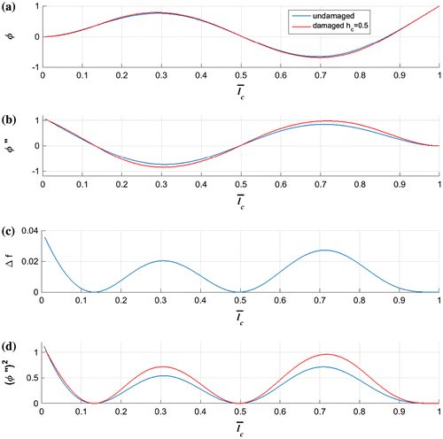
Figure 3. The effect of bending near the crack. (a) at the inflexion point, (b) at the maximum displacement of the mode shape, and (c) at the minimum displacement of the mode shape [Citation49].
![Figure 3. The effect of bending near the crack. (a) at the inflexion point, (b) at the maximum displacement of the mode shape, and (c) at the minimum displacement of the mode shape [Citation49].](/cms/asset/e183b02e-d8fa-4efb-a277-3181aa840251/gipe_a_1442834_f0003_oc.gif)
Table 1. The properties and dimensions of the beam.
Figure (c) shows the 3rd frequency change () as function of the damage location for
. One can see that the frequency remains unchanged when the damage is located in the curvature mode shape node, respectively, in the inflexion point of the mode shape. Also, the frequency has a maximum reduction when the damage is located in the maximum or minimum displacement of mode shape, respectively, in the minimum or maximum displacement of curvature.
According to [Citation49–51], the beam has not a vertical displacement in the inflexion points and it does not undergo a bending; it just undergoes a rotation as it can be seen from Figure (a), consequently the stored strain energy remains unchanged, hence, the natural frequency remains unchanged when the damage is located in the inflexion point of the mode shape (respectively in the curvature node). In contrast, the beam undergoes the highest bending in the maximum or minimum displacement of the mode shape (see Figure (b) and (c) respectively), consequently it produces the largest loss of stored strain energy, hence, the natural frequency has the highest reduction when the damage is located in the maximum or minimum displacement of the mode shape (respectively in the minimum or maximum of the curvature).
Table 2. Simulated damage cases and corresponding relative frequencies (Δf).
Table 3. Results and errors for the detection of the damage location and its depth.
Table 4. The properties and dimensions of the experimental beam.
Table 5. The measured natural frequencies (Hz) of the cantilever beam.
Table 6. The change in the natural frequencies for the experimental application.
Table 7. Damage detection using the first three frequencies (first approach).
Table 8. Damage detection using the first four frequencies (first approach).
Table 9. Damage detection using the first three frequencies (second approach).
Table 10. Damage detection using the first four frequencies (second approach).
According to Vable [Citation76], the mode shape curvature is directly related to the stored strain energy (U) and the relation between them at each location l is:
(18)
(18)
So, the natural frequency changes as function of the stored strain energy, and the stored strain energy changes as function of the squared curvature mode shape. Consequently, the natural frequency changes as function of the squared curvature mode shape. Figure (c) and (d) show that the curve of the relative natural frequency reduction has the same allure as the one of the squared curvature mode shape.
The blue-solid lines and the red-dashed lines in Figure show that the effect of the crack on the mode shapes is not very important and it produces a small shift near the damage position, which gives that the allure of the intact mode shapes (or their derivatives) is almost the same allure of the damaged ones (Figure ) but with a slight amplification. So, the data from the intact structure can be used instead of the damaged one for the following reasons:
In the numerical studies, for the damaged curvature mode shapes, we have to simulate many times with several damage locations to get the data, unlike for the intact curvature mode shapes which represent the case before the damage.
In the experimental studies the intact curvature mode shapes can be measured once and before the structure is put into service. In contrast, the damaged ones represent the current state of the structure and they have to be measured for each detection, which takes time and efforts since the measurement of the mode shapes requires, either the use of several sensors, or the measurement of several FRF with an impact at different positions.
Figure 4. Relation between Δf and for the first three modes. (a)
as function of damage location, (b)
as function of damage location, (c)
as function of damage location, (d) squared damaged curvature
, and (e) squared intact curvature
.
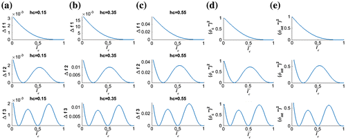
where the coefficient (ζ) and (β) controls the effect of the damage severity, and the squared curvature mode shape at the distance l
c
from the fixed end controls the effect of the damage location.
The Equation (19) can be written as:
(20)
(20)
where the can be measured and
can be either calculated using Equation (15) or derived from the measured mode shape. Thus, the Equation (Equation20
(20)
(20) ) can be represented as:
(21)
(21)
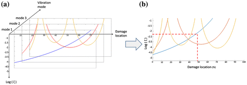
As shown in Figure , the coefficient (ζ) in Equation (Equation21(21)
(21) ) calculated for different vibration modes (Figure (a)) can be plotted in the same axis (Figure (b)), and the intersection of the plotted curves gives the damage location and the coefficient (ζ).
It is noted that the vectors of the plotted curves are composed of small and great value which varies between 10−6 and 10+10. So, in order to get an intersection more visible, it is better to plot the coefficient (ζ) in the logarithmic form.
In some cases, the intersection of the contour lines of the first two modes may intersect more than one point, indicating more than one solution. In order to ensure a unique solution, the use of the first three modes is required.
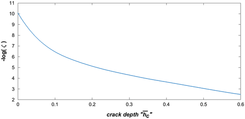
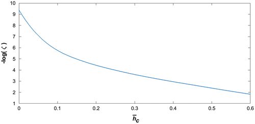
In order to predict the damage severity, an inverse method is used to estimate the relationship between the coefficient (ζ) and the damage depth. The coefficient (ζ) is calculated as function of several damage depths in the fixed location = 10% for the beam dimension presented in Table . This fixed location has been chosen after several tests to reduce the error. The results are interpolated from the adjacent values using a MATLAB function ‘cubic spline interpolation’ and they are presented in Figure .
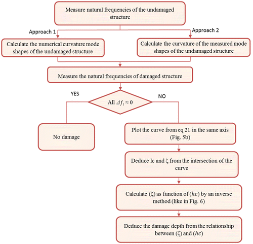
Figure shows the flowchart of the present method of damage detection.
3.1. Notes
Due to the inevitable presence of the simulation or measurement errors related to the measurement noise, fixed boundary condition which is very difficult to realise in the experimental set-up, the ignorance of the effect of damping in the finite element analysis and the loss of mass occurring in the case of open cracks, there may be cases in which the plotted contour lines can be intersected in three approached points and produces a triangle. So, the average of the results given by the three points is required.
4. Numerical simulation
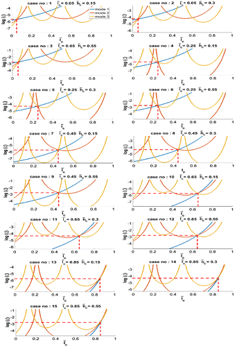
In this section, the effectiveness of the proposed method is shown using numerical data. This numerical application gives the opportunity to show the robustness of the proposed method in detecting the damage location and its severity since it is exempted from inevitable noise in the experimental set-up. The dimension and the material of the cantilever beam (Figure ) used in this numerical simulation are presented in Table . Fifteen cases are studied in this section where the location of the damage and its depth vary in each case. The first three relative frequencies (Δf) are calculated for each case and presented in Table . Using these relative frequencies and following the approach presented above, a contour line as function of the damage location and the coefficient (ζ) is plotted for the first three modes and the intersection of the three curves gives the damage location and the coefficient (ζ) (see Figure ). Then, the damage severity is concluded using the relationship between the damage depth and the coefficient (ζ) from Figure . The results of the damage location and its severity are presented in Table ; the error value reported in this table is calculated using the following equation:(22)
(22)
The results in Table show that the detected damage parameters are closed to the exact value with an error between 0.01 and 0.1% for the damage location and an error between 0.02 and 0.49% for the damage depth. These results are still admissible when compared to the results obtained in other works [Citation45–75]. As conclusion, the contours of the first three natural frequencies and the corresponding undamaged mode shapes can be used to detect damage in beam-like structure.
5. Experimental set-up
An experimental framework on cantilever beams has been designed to verify the practical applicability of the theoretical method developed in the previous section. The detailed experimental procedure is described in the following section. The damage detection has been established using two approaches. In one of them the curvature mode shapes are calculated numerically and in the other one, they are derived from the measured mode shapes of the intact beam.
5.1. The experimental procedure
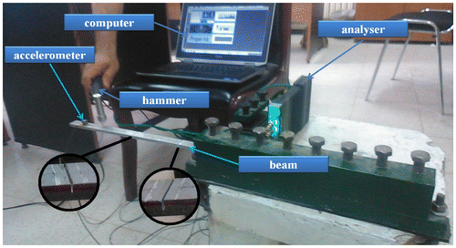
Figure represents the experimental framework carried out in the laboratory. The dimension and the material of the cantilever beam are represented in Table . The beam has been excited by an Impact Hammer (Type 8206-001), which produces a force and measures it at the same time. The dynamic response of the beam has been measured using one accelerometer mounted at distances of 330 mm from the fixed-end of the beam, a 6 Channel Pulse Vibration Analyser and Vold–Kalman filter attached to a computer. Data reduction software using FFT has been used to obtain the frequency response function (FRF) of the beam, and hence the natural frequencies of the beam. The structural response has been measured within sampling frequency of 6400 points for a frequency range of 0–2 kHz. First, the intact beams have been tested. Here, the intact beam has been excited in 18 equidistant points to define the mode shapes of the undamaged structure to be used in the second approach. The mode shape is determined from the peak amplitude of the imaginary part of the FRFs calculated from each excitation. More precisely, the peak amplitude of the imaginary FRF of the mode ‘i’ calculated with an excitation at the location ‘l’, gives the displacement of the mode shape ‘i’ at the location ‘l’ (see reference [Citation77]). The resulting vector is divided by its greatest value to get a normalized mode shape.
Then, the damage has been introduced in the transversal axis by a saw cut with a severity h c1 = 1.9 mm at the location l c1 = 57 mm from the fixed-end and the natural frequencies have been measured. Then, the crack depth has been increased to h c2 = 4.2 mm and the natural frequencies of the second case have been measured. For the third case, the beam with the first damage is considered as an intact beam and a crack with h c3 = 3.4 mm has been introduced at the location l c3 = 178.6 mm from the fixed-end.
In order to reduce the error in the damage detection due to the measurement noise, in this experimental part, the first four natural frequencies are considered and the results are compared with the use of only the first three ones. The concept is to plot the contours of the first four frequencies instead of the first three ones, and the three most accurate frequencies which produce the smallest triangle are selected.
The measured natural frequencies before and after the damage are represented in Table and the relative changes in these frequencies are represented in Table to be used for the damage detection.
In the next sections, two approaches of damage detection (based on the previous method) are presented. In the first approach the curvatures mode shapes are derived from the numerical mode shape and in the second one the curvatures mode shapes are derived from the measured one.
5.2. First approach: detection using numerical mode shape
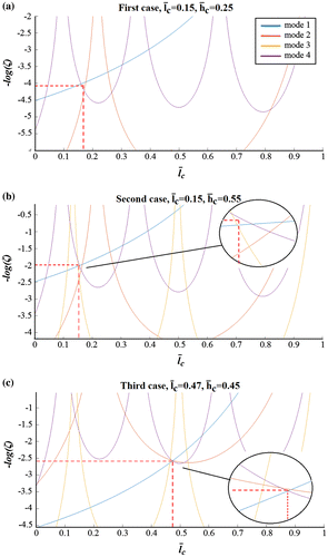
Like in the numerical simulation studied in the previous section, the curvature mode shape is derived from the numerical mode shape. The first four relative measured frequencies (Δf) are presented in Table . Using these relative frequencies and following the approach presented above, contour lines as function of the damage location and the coefficient (ζ) are plotted for the first four modes and the intersection of the curves gives the damage location and the coefficient (ζ) (Figure ). For the damage quantification, like for the beam of Table , the inverse method is used to give a relationship between the damage depth and the coefficient (ζ) and the results are presented in Figure . Then, the damage quantification is concluded from Figure .
First, the results from the intersection of the first three modes are presented in Table . Then, the results from the intersection of the three most accurate modes which produce the smallest triangle are presented in Table . The results are discussed in Section 5.3.
5.3. Second approach: detection using measured mode shape
In this section, the damage detection is carried out using only the measured modal analysis data. The relative changes in the natural frequencies are used in addition to the curvature mode shapes derived from the measured mode shapes of the intact structure.
The first four measured mode shapes are normalized and represented by points in Figure . Then, they are interpolated from the adjacent values using a MATLAB function ‘cubic spline interpolation’ and represented in (Figure , solid lines). The measured mode shapes are compared with numerical results (Figure dashed lines).
Figure 12. The first four normalized mode shapes. (points (.): measured data/solid lines (-): interpolate from measured data/dashed lines (---): numerical data).
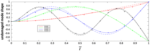
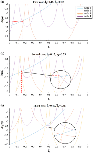
In order to detect the damage, the interpolated mode shapes are derived and used with the relative frequency in Equation (23) to plot a contour (Figure ).(23)
(23)
First, the results from the intersection of the first three modes are presented in Table . Then, the results from the intersection of the three most accurate modes which produce the smallest triangle are presented in Table . The results are discussed in Section 5.3.
5.4. Discussion
It can be observed that the first case of damage is a special case where one of the natural frequencies remains unchanged and cannot be used to plot the contour lines. So, using only the first two frequencies there is a double solution: the first at the location = 0.17 and the second at the location
= 0.25 (at the locations
0.18 and 0.25, using the second approach). But, it is clear in Figures and that the third frequency remains unchanged near the nodes
= 0.13 and
= 0.50. So, the first solution is considered. However, the use of four frequencies avoids this double solution and confirms these results.
According to the results of the damage detection, it was observed that the predicted locations are closed to the real locations using the first approaches, and this, with an error between 0.19 and 2.66% using the first three frequencies and between 0.15 and 1.9% using the first four frequencies. Also, the predicted severities are closed to the real ones, with an error between 0.4 and 2.2% using the first three frequencies and between 1 and 2.6% using first four frequencies.
The results obtained through the second approach show that the error is larger, because the measured mode shapes used for the detection are affected by the measurement noise compared to the ones used in the first approach which is exempted from the noise. For the damage location, the error is between 1.1 and 3.3% using the first three frequencies and between 0.4 and 2.4% using the first four frequencies. For the damage severity, it is between 1.7 and 2.5% using the first three frequencies and between 0.7 and 4.5% using the first four frequencies.
The results in the two approaches show that:
Generally, the use of more frequencies reduces the errors in the damage localization and avoids the multiple solutions in the special cases of the unchanged frequency, such as in the first case where the third frequency remains unchanged.
The error has a great value when the damage severity is smaller; this is because when the damage depth is smaller, the change in the frequencies is smaller, so it is more affected by the noise, and that increases the error. So, more the filter is better, more the smaller damage can be detected.
The first approach is simpler and more accurate. In other words, it avoids the measurement of the mode shapes disturbed by the measurement noise. But in some cases, measuring the mode shape of the intact structure is simpler than modelling the structure.
The presence of the measurement noise
The difficulty to achieve the fixed boundary condition in the experimental set-up
The ignorance of the effect of damping in the finite element analysis
The accelerometer mass slightly modifies the structure [Citation37–39]
The saw cut produces a slightly different damage compared to the one modelled by FEM.
6. Conclusion
A new method for structural damage detection has been developed in this paper. First, a relationship has been presented between the decrease in the natural frequencies due to the damage and the curvature mode shapes. Then, an equation has been developed in order to plot curves as function of the damage location and the coefficient (ζ) (which stays for the damage severity). These curves are plotted only using the measured frequencies and the curvature mode shape derived from the calculated or measured mode shape, in which the intersection of the plotted curves for the first three modes gives the damage location and the coefficient (ζ). Then, a relationship between the coefficient (ζ) and the damage depth has been established using an inverse problem in order to predict a damage severity. The advantage of the proposed method is that it does not require neither the solving of the governing differential equation analytically to obtain the contour line, nor the calculation of the frequencies by varying all damage severities and locations in order to use an inverse problem to plot a contour as in the methods presented in [Citation64–75].
Several sets of numerical simulations have been carried out to examine the robustness and the effectiveness of the damage detection method. The obtained results show that the proposed method can be applicable in the damage location and quantification without the need of modelling the damage.
Finally, in order to verify the practical applicability of the developed theoretical method, an experimental framework on cantilever beam has been designed. The damage detection has been established using two approaches. In the first approach the curvature mode shapes are derived from the numerical mode shapes, and in the second one the curvatures mode shapes are derived from the measured ones. The results have clearly shown that the first approach is simpler and more accurate. In other words, it avoids the measurements of the mode shapes disturbed by the measurement noise. But in some cases, measuring the mode shape of the intact structure is simpler than modelling the structure. However, the results are still admissible for the two approaches when they are compared to the results obtained in other works [Citation45–75]. Therefore, the method can be used to detect damages, with the following attributes:
The possibility to detect the damage using only the experimental data collected from the structure.
Less calculation compared to other frequencies contours methods or optimization approaches.
A non-requiring of any theoretical model of the damaged structure to detect the damage.
A need of a very cheap experimental procedure and the dynamic response of the beam can be measured using only one accelerometer.
Disclosure statement
No potential conflict of interest was reported by the authors.
Acknowledgement
The authors appreciate the efforts and assistance of Mr Athmane DAHAK for his support and help to revise the English grammar and style which have improved the quality of this paper.
References
- Doebling SW , Farrar CR , Prime MB , et al. Damage identification and health monitoring of structural and mechanical systems from changes in their vibration characteristics: a literature review. Los Alamos National Laboratory report; 1996. ( LA-13070-MS).10.2172/249299
- Doebling SW , Farrar CR , Prime MB . A summary review of vibration-based damage identification methods. 1998;30(2):91–105.
- Sohn H , Farrar CR , Hemez FM , et al. A review of structural health monitoring literature: 1996–2001. Massachusetts Institute of Technology, Los Alamos National Laboratory report; 2004. (LA-13976-MS).
- Sinou JJ . A review of damage detection and health monitoring of mechanical systems from changes in the measurement of linear and non-linear vibrations. In: Sapri RC , editor. Mechanical vibrations: measurement, effects and control. Nova Science; 2009. p. 643–702.
- Fan W , Qiao P . Vibration-based damage identification methods: a review and comparative study. Struct Health Monit. 2011;83–111.10.1177/1475921710365419
- Jassim ZA , Ali NN , Mustapha F , et al. A review on the vibration analysis for a damage occurrence of a cantilever beam. Eng Failure Anal. 2013;31:442–461.
- Das S , Saha P , Patro SK . Vibration-based damage detection techniques used for health monitoring of structures: a review. J Civil Struct Health Monit. 2016;6(3):477–507.10.1007/s13349-016-0168-5
- Qing XP , Beard SJ , Kumar A , et al. The performance of a piezoelectric-sensor-based SHM system under a combined cryogenic temperature and vibration environment. Smart Mater Struct. 2008;17(5):1–11.
- Wu Q , Yu F , Okabe Y , et al. Application of a novel optical fiber sensor to detection of acoustic emissions by various damages in CFRP laminates. Smart Mater Struct. 2014;24(1):015011.
- Lam PM , Lau KT , Ling HY , et al. Acousto-ultrasonic sensing for delaminated GFRP composites using an embedded FBG sensor. Opt Lasers Eng. 2009;47(10):1049–1055.10.1016/j.optlaseng.2009.01.010
- Cao MS , Sha GG , Gao YF , et al. Structural damage identification using damping: a compendium of uses and features. Smart Mater Struct. 2017;26:043001 14pp.10.1088/1361-665X/aa550a
- West WM . Illustration of the use of modal assurance criterion to detect structural changes in an orbiter test specimen. Proceedings of the Air Force Conference on Aircraft Structural Integrity. Los Angeles, CA; 1984. p. 1–6.
- Lieven N , Ewins D . Spatial correlation of mode shapes: the coordinate modal assurance criterion (COMAC). Proceedings of the 6th International Modal Analysis Conference, Kissimmee, FL, USA; 1988. Vol. 1, p. 690–695.
- Heylen W . Extensions of the modal assurance criterion. J Vib Acoust. 1990;112:468–472.10.1115/1.2930130
- O’Callahan J . Correlation considerations – Part 4 (Modal vector correlation techniques). Proceedings of the 16th International Modal Analysis Conference. Santa Barbara, CA; 1998. p. 197–206.
- Brechlin E , Bendel K , Keiper W . A new scaled modal assurance criterion for eigenmodes containing rotational degrees of freedom. Proceedings of International Seminar on Modal Analysis, ISMA23. Noise and vibration engineering; 1998. p. 1175–1182.
- Allemang RJ . The modal assurance criterion – twenty years of use and abuse. Sound Vibr. 2003;37(8):14–23.
- Abdo MA-B , Hori M . A numerical study of structural damage detection using changes in the rotation of mode shapes. J Sound Vibr. 2002;251(2):227–239.10.1006/jsvi.2001.3989
- Pandey A , Biswas M , Samman M . Damage detection from changes in curvature mode shapes. J Sound Vibr. 1991;145:321–332.10.1016/0022-460X(91)90595-B
- Roy K , Ray-Chaudhuri S . Fundamental mode shape and its derivatives in structural damage localization. J Sound Vibr. 2013;332:5584–5593.
- Gladwell GML , Morassi A . Estimating damage in a rod from changes in node positions. Inverse Prob Eng. 1999;7:215–233.10.1080/174159799088027695
- Xiang JW , Matsumoto T , Long JQ , et al. Identification of damage locations based on operating deflection shape. Nondestr Test Eval. 2013;28(2):166–180.10.1080/10589759.2012.716437
- Ratcliffe CP , Bagaria WJ . A vibration technique for locating delamination in a composite beam. Am Inst Aeronaut Astronaut J. 1998;36(6):1074–1077.10.2514/2.482
- Wu D , Law SS . Damage localization in plate structures from uniform load surface curvature. J Sound Vibr. 2004;276:227–244.10.1016/j.jsv.2003.07.040
- Gherlone M , Mattone M , Surace C , et al. Novel vibration-based methods for detecting delamination damage in composite plate and shell laminates. Key Eng Mater. 2005;293–294:289–296.10.4028/www.scientific.net/KEM.293-294
- Rucevskis S , Wesolowski M , Chate A . Vibration-based damage identification in laminated composite beams. Constr Sci. 2009;10(10):100–112.
- Rucevskis S , Janeliukstis R , Akishin P , et al. Mode shape-based damage detection in plate structure without baseline data. Struct Control Health Monit. 2016;23(9):1180–1193.10.1002/stc.v23.9
- Chang CC , Chen LW . Vibration damage detection of a Timoshenko beam by spatial wavelet based approach. Appl Acoust. 2003;64(12):1217–1240.10.1016/S0003-682X(03)00070-7
- Chang C-C , Chen L-W . Detection of the location and size of cracks in the multiple cracked beam by spatial wavelet based approach. Mech Syst Signal Process. 2005;19:139–155.10.1016/j.ymssp.2003.11.001
- Zhong S , Oyadiji SO . Crack detection in simply supported beams without baseline modal parameters by stationary wavelet transform. Mech Syst Signal Proc. 2007;21:1853–1884.10.1016/j.ymssp.2006.07.007
- Xiang J , Liang M . Wavelet-based detection of beam cracks using modal shape and frequency measurements. Computer-Aided Civ Infrastruct Eng. 2012;27:439–454.10.1111/mice.2012.27.issue-6
- Jaiswal NG , Pande DW . Sensitizing the mode shapes of beam towards damage detection using curvature and wavelet transform. Int J Sci Technol Res. 2015;4(4):266–272.
- Algaba M , Solís M , Galvín P . Wavelet based mode shape analysis for damage detection. Proceedings of the 30th IMAC, A Conference on Structural Dynamics. Jacksonville, FL; 2012; p. 377–384.
- Solís M , Algaba M , Galvín P . Continuous wavelet analysis of mode shapes differences for damage detection. Mech Syst Signal Process. 2013;40:645–666.10.1016/j.ymssp.2013.06.006
- Cao M , Radzieński M , Xu W , et al. Identification of multiple damage in beams based on robust curvature mode shapes. Mech Syst Signal Process. 2014;46:468–480.10.1016/j.ymssp.2014.01.004
- Kim J-T , Ryu Y-S , Cho H-M , et al. Damage identification in beam-type structures: frequency-based method vs mode-shape-based method. Eng Struct. 2003;25:57–67.10.1016/S0141-0296(02)00118-9
- Chen DM , Xu YF , Zhu WD . Non-model-based multiple damage identification of beams by a continuously scanning laser Doppler vibrometer system. Measurement. 2018;115:185–196.10.1016/j.measurement.2017.09.017
- Chen DM , Xu YF , Zhu WD . Damage identification of beams using a continuously scanning laser Doppler vibrometer system. J Vib Acoustics. 2016;138(5):051011.10.1115/1.4033639
- Xu YF , Zhu WD , Liu J , et al. Identification of embedded horizontal cracks in beams using measured mode shapes. J Sound Vib. 2014;333:6273–6294.10.1016/j.jsv.2014.04.046
- Xiang J , Matsumoto T , Long J , et al. A simple method to detect cracks in beam-like structures. Smart Struct Syst. 2012;9(4):335–353.10.12989/sss.2012.9.4.335
- Xiang J , Matsumoto T , Wang Y , et al. Detect damages in conical shells using curvature mode shape and wavelet finite element method. Int J Mech Sci. 2013;66:83–93.10.1016/j.ijmecsci.2012.10.010
- Xiang J , Nackenhorst U , Wang Y , et al. A new method to detect cracks in plate-like structures with though-thickness cracks. Smart Struct Syst. 2014;14(3):397–418.10.12989/sss.2014.14.3.397
- Jiang YY , Xiang J , Li B , et al. A hybrid multiple damages detection method for plate structures. Sci China Tech Sci. 2017;60(5):726–736.10.1007/s11431-016-9002-0
- Salawu OS . Detection of structural damage through changes in frequency: a review. Eng Struct. 1997;19(9):718–723.10.1016/S0141-0296(96)00149-6
- Cawley P , Adams RD . The location of defects in structures from measurements of natural frequencies. J Strain Anal. 1979;14(2):49–57.10.1243/03093247V142049
- Messina A , Jones IA , Williams EJ . Damage detection and localisation using natural frequency changes. Proceedings of Conference on Identification in Engineering Systems. Swansea, UK; 1996. p. 67–76.
- Contursi T , Messina A , Williams EJ . A multiple-damage location assurance criterion based on natural frequency changes. J Vib Control. 1998;4(5):619–633.10.1177/107754639800400505
- Messina A , Contursi T , Williams EJ . Multiple damage evaluation using natural frequency changes. Proceedings of the 15th International Modal Analysis Conference. 1997;1:658–664.
- Gillich GR , Praisach ZI . Robust method to identify damages in beams based on frequency shift analysis. Proceedings of SPIE The International Society for Optical Engineering. San Diego, CA; 2012. Vol. 8348, p. 83481D.
- Gillich GR , Praisach ZI . Modal identification and damage detection in beam-like structures using the power spectrum and time-frequency analysis. Signal Proc. 2014;96:29–44.10.1016/j.sigpro.2013.04.027
- Gillich GR , Maia NMM , Mituletu IC , et al. Early structural damage assessment by using an improved frequency evaluation algorithm. Latin Am J Solids Struct. 2015;12(12):2311–2329.10.1590/1679-78251795
- Dahak M , Touat N , Benseddiq N . On the classification of normalized natural frequencies for damage detection in cantilever beam. J Sound Vib. 2017 Aug;402(18):70–84.10.1016/j.jsv.2017.05.007
- Moradi S , Razi P , Fatahi L . On the application of bees algorithm to the problem of crack detection of beam-type structures. Comput Struct. 2011;89:2169–2175.10.1016/j.compstruc.2011.08.020
- Moradi S , Kargozarfard MH . On multiple crack detection in beam structures. J Mech Sci Technol. 2013;27(1):47–55.10.1007/s12206-012-1230-9
- Moezi SA , Zakeri E , Zare A , et al. On the application of modified cuckoo optimization algorithm to the crack detection problem of cantilever Euler–Bernoulli beam. Comput Struct. 2015;157:42–50.10.1016/j.compstruc.2015.05.008
- Kaminski PC . The approximate location of damage through the analysis of natural frequencies with artificial neural networks. J Proc Mech Eng. 1995;209:117–123.10.1243/PIME_PROC_1995_209_238_02
- Vakil-Baghmisheh M-T , Peimani M , Sadeghi MH , et al. Crack detection in beam-like structures using genetic algorithms. Appl Soft Comput. 2008;8:1150–1160.10.1016/j.asoc.2007.10.003
- Buezas FS , Rosales MB , Filipich CP . Damage detection with genetic algorithms taking into account a crack contact model. Eng Fract Mech. 2011;78:695–712.10.1016/j.engfracmech.2010.11.008
- Meruane V , Heylen W . An hybrid real genetic algorithm to detect structural damage using modal properties. Mech Syst Signal Process. 2011;25:1559–1573.10.1016/j.ymssp.2010.11.020
- Khaji N , Mehrjoo M . Crack detection in a beam with an arbitrary number of transverse cracks using genetic algorithms. J Mech Sci Technol. 2014;28(3):823–836.10.1007/s12206-013-1147-y
- Krawczuk M . Application of spectral beam finite element with a crack and iterative search technique for damage detection. Finite Elem Anal Des. 2002;38:537–548.10.1016/S0168-874X(01)00084-1
- Ding Z , Lu Z , Huang M , et al. Improved artificial bee colony algorithm for crack identification in beam using natural frequencies only. Inverse Prob Sci Eng. 2016;25(2):218–238.
- Boubakir L , Touat N , Kharoubi M , et al. Application of improved accelerated random search algorithm for structural damage detection. Int J Acoust Vib. 2017;22(3):353–368.
- Liang RY , Choy FK , Hu J . Detection of cracks in beam structures using measurements of natural frequencies. J Franklin Inst. 1991;328(4):505–518.10.1016/0016-0032(91)90023-V
- Lele SP , Maiti SK . Modelling of transverse vibration of short beams for crack detection and measurement of crack extension. J Sound Vib. 2002;257(3):559–583.10.1006/jsvi.2002.5059
- Rosales MB , Filipich CP , Buezas FS . Crack detection in beam-like structures. Eng Struct. 2009;31:2257–2264.10.1016/j.engstruct.2009.04.007
- Chinchalkar S . Determination of crack location in beams using natural frequencies. J Sound Vib. 2001;247(3):417–429.10.1006/jsvi.2001.3748
- Nikolakopoulos PG , Katsareas DE , Papadopoulos CA . Crack identification in frame structures. Comput Struct. 1991;64(14):389–406.
- Owolabi GM , Swamidas ASJ , Seshadri R . Crack detection in beams using changes in frequencies and amplitudes of frequency response functions. J Sound Vib. 2003;265:1–22.10.1016/S0022-460X(02)01264-6
- Dong GM , Chen J , Zou J . Parameter identification of a rotor with an open crack. Eur J Mech A. Solids. 2004;23:325–333.10.1016/j.euromechsol.2003.11.003
- Nahvi H , Jabbari M . Crack detection in beams using experimental modal data and finite element model. Int J Mech Sci. 2005;47:1477–1497.10.1016/j.ijmecsci.2005.06.008
- Swamidas ASJ , Yang X , Seshadri R . Identification of cracking in beam structures using Timoshenko and Euler formulations. J Eng Mech. 2004;130:1297–1308.10.1061/(ASCE)0733-9399(2004)130:11(1297)
- Sinou JJ . Damage assessment based on the frequencies’ ratio surfaces intersection method for the identification of the crack depth location and orientation. Struct Durability Health Monit. 2007;3(3):134–162.
- Mazanoglu K , Sabuncu M . A frequency based algorithm for identification of single and double cracked beams via a statistical approach used in experiment. Mech Syst Signal Process. 2012;30:168–185.10.1016/j.ymssp.2012.02.004
- Banerjee A , Panigrahi B , Pohit G . Crack modeling and detection in Timoshenko FGM beam under transverse vibration using frequency contour and response surface model with GA. Nondestr Test Eval. 2016;31:142–164.
- Vable M . Intermediate mechanics of materials. New York (NY): Oxford University Press; 2008.
- Avitabile P . Experimental modal analysis: a simple non-mathematical presentation. Sound Vib; 2001;35:20–31.


