 ?Mathematical formulae have been encoded as MathML and are displayed in this HTML version using MathJax in order to improve their display. Uncheck the box to turn MathJax off. This feature requires Javascript. Click on a formula to zoom.
ABSTRACT
We deal with the mathematical model of the incremental degradation of the internal coating (e.g. a polymeric material) of a metallic pipe in which a fluid flows relatively fast. The fluid drags solid impurities so that longitudinal scratches, inaccessible to any direct inspection procedure, are produced on the coating. Time evolution of this kind of defects can be reconstructed from the knowledge of a sequence of temperature maps of the external surface. The time-varying orthogonal section of this damaged interface is determined as a function of time and polar angle through the identification of a suitable effective heat transfer coefficient by means of Thin Plate Approximation.
1. Introduction
The present paper deals with the identification of a time-dependent defect affecting the internal coating of a tube inaccessible to direct observation. Time evolution of the damaged interface between the coating and the fluid that flows inside can be reconstructed from a sequence of measurements of the temperature taken on the accessible external surface of the tube. In other words, we must solve an inverse problem for the heat conduction equation in a coated cylinder.
In [Citation1], we exploit a limit property of the temperature for vanishing coating in order to set an ‘equivalent’ model in the cylinder. The unknown in the new problem is an effective heat transfer coefficient explicitly related to the variable thickness of the damaged coating. In [Citation1], neither the coating nor
depend on time. Furthermore, temperature is stationary and fulfills Laplace’s equation. Here, we assume that the defect of the coating evolves in the same time scale (or in a smaller one) as data so that, in fact, there is an unknown moving interface between the coating and the fluid flowing inside the tube. The problem of tracking the time evolution of defects is approached by means of a generalization of the method introduced in [Citation1]. We stress that the derivation of
is no more based on the explicit solution of potential equation as was in the stationary case.
Since real data are so far not available, at this stage, we work with numerical simulations as realistic as possible.
As long as we deal with a thin-walled tube, we recover by means of an algorithm based on the Thin Plate Approximation (TPA). TPA is essentially a practical iterative method for computing approximated solutions of Cauchy’s problem for the heat equation. Alternative more costly optimization-based strategies could be preferred when the thickness is large (see for example in [Citation2,Citation3] and [Citation4]).
Remark:
The detection of time-varying defects calls to mind one-phase Moving Free Boundary Problems (MFBP) for the heat equation (see the seminal paper [Citation5] and see [Citation6] for the state of the art). Actually, here the additional information (required to determine the unknown of an inverse problem) is assigned on the external fixed boundary, whilst in MFBP it is usually given on the free boundary. Other examples of parabolic problems on time-varying domains are described in [Citation7] (a survey with a huge reference section), [Citation8] (crystal growth processes) and [Citation9] (moving phase boundaries). Amongst the wide numerical literature we cite [Citation10,Citation11] (a moving boundary problem is handled like a nonlinear problem in a fixed domain), [Citation12] (a Locally One-Dimensional method for the numerical solution of a two-dimensional fusion problem) and [Citation13] (a conservative algorithm is developed for modelling cell biology).
2. The direct model and its limit for vanishing coating
Although we deal with the 3D specimens (the intact internally coated tube) and
(the tube whose coating is damaged), we are naturally driven to a 2D problem. In fact, we assume that defects are due to solid impurities which, travelling fast inside the tube, can produce longitudinal scratches. Hence, a cross section of
orthogonal to its axis includes all local features of the defects.
2.1. Geometry of the problem
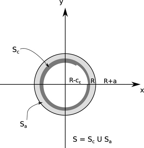
Assume that the intact tube is where
with and
. Actually,
is the thickness of the coating. The parameter
allows to send thickness to zero when required by the mathematics of the problem. R and a are the internal radius of the metallic tube and its thickness.
Similarly, the damaged specimen is where
with and
is a smooth periodic function.
Hence, has external radius
and it is internally bounded by the surface
where
,
and a positive constant
exists such that
The shell of radii
(external radius) and R (internal one) is supposed to be a good thermal and electrical conductor, while the cylindrical coating
is usually characterized by low thermal and electrical conductivity. Thermal conductivities are
in
and
in
.
In what follows, and
are orthogonal sections, for a chosen
, of
and
, respectively. Clearly
. The geometrical and physical characteristics of the coating depend on the real adimensional parameter
(directly proportional to the thickness of the coating).
When the coating is intact, (constant in
and t). The time evolution of the damage is fully described by the monotone family of closed plane curves
parameterized by
.
2.2. Physical model
Assume that is subjected to heating by connecting a couple of electrodes along the tube so that the coordinate
stands between the electrode positions. Let
and
be the powers (per unit of volume dissipated by Joule effect) and let
and
be the volumetric heat capacity in the metallic tube and in the coating, respectively.
The temperature u in the section S fulfills the 2D parabolic PDE (heat conduction equation in polar coordinates)(1)
(1)
in with
where if
and
if
. The subscript c means that the quantity is in the coating (and then it depends on the parameter
), while the subscript a means that we are in the tube section.
The problem is two-dimensional due to the damage geometry, and because the conductive properties of the metallic tube are such to give an axial electric potential, i.e. only dependent on the z coordinate.
The definition of the thermal model is completed by:
| (1) | Boundary conditions | ||||
| (2) | Initial temperature, constant everywhere in S | ||||
| (3) | ‘transmission conditions’ | ||||
2.3. Limit for vanishing coating
We assume(5)
(5)
and define as the unique solution of the following Initial Boundary Value Problem:
(6)
(6)
for ,
(7)
(7)
(8)
(8)
(9)
(9)
where(10)
(10)
Existence of a unique solution of IBVP (Equation6(6)
(6) )–(Equation9
(9)
(9) ) is shown in [Citation14].
The assumption (Equation5(5)
(5) ) allows to transform the original problem (Equation1
(1)
(1) )–(Equation4
(4)
(4) ) (i.e. tube with damaged internal coating) into an equivalent one (Equation6
(6)
(6) )–(Equation9
(9)
(9) )(i.e. bare tube with an effective heat transfer coefficient depending on time and angle variables) analogously to [Citation1]. We state the theoretical result on which we base the reconstruction strategy described in the next section. In fact, we have
(11)
(11)
This relation defines the physical meaning of as the temperature of the tube when the coating is thin enough. A formal derivation of (Equation11
(11)
(11) ) is given in Appendix 1. We stress that this relation generalizes the limit properties in [Citation1] to the case of time varying interfaces.
3. Defect reconstruction
The function describes the shape of the coating as a function of the angle
at the instant t for any fixed vale of the parameter
. Hence, it includes full information about the status of the interface between the coating and the internal fluid. More precisely, the quantity
is the defect size in the radial direction
. Clearly, when the interface is undamaged, we have
.
The inverse problem described in the introduction consists of the approximation of from the knowledge of the external temperature of the tube
(a quantity, possibly affected by noise, measured in practice by means of an infrared camera) once the geometrical and physical parameters R, a,
,
,
,
,
,
,
,
,
,
and
are given.
We approximate in two steps:
Step 1. Compute the coefficient in (Equation9
(9)
(9) ) under the assumption that
is equal to the measured external temperature.
Step 2. Solve (Equation10(10)
(10) ) with respect to
and set
.
3.1. Step 1: reconstruction of 
 from the external temperature
A time-varying heat transfer coefficient can be evaluated in many different ways: optimization algorithms [Citation4,Citation15], statistical methods in one dimension [Citation2], variational methods [Citation14] and thermal experiments [Citation16]. Since , we obtain a fast and reliable estimate of
by means of the Thin Plate Approximation (TPA) (see [Citation1,Citation17,Citation18]). TPA is an iterative method used to produce approximate solutions of inverse problems whose unknown is defined on the inaccessible boundary of a thin domain. The method is based on the formal solution of a suitable Cauchy problem for heat equation.
In what follows, heat transfer coefficients , and
and
will be scaled by the shell thickness a in order to avoid singularities in the Thin Plate Approximation.
When the coating is intact (i.e. its thickness is ), the equivalent uncoated system is modelled by the one-dimensional IBVP
(12)
(12)
for ,
(13)
(13)
in
(14)
(14)
(15)
(15)
with(16)
(16)
Although should be a known technical characteristic of coating, it is realistic to assume only a rough knowledge of its numerical value. Nevertheless, we can easily derive its value from the external temperature in points far from the defect. For this reason, it is natural to assume that
is the sum of a background value (corresponding to the undamaged coating) and a perturbative term:
It comes from linearity and well-posedness of (Equation6(6)
(6) )–(Equation9
(9)
(9) ) that its solutions can be written as
where is the background temperature corresponding to
.
It is easy to check that the thermal contrast satisfies the homogeneous heat equation:
with boundary conditions:
and initial data
We transform the radial coordinate r into and define
(relative thickness of the shell),
(thermal contrast in the new variables)
(normalized conductivity) and
.
In the new variables, the IBVP in becomes
(17)
(17)
for ,
(18)
(18)
(19)
(19)
where .
Plugging the expansions(20)
(20)
(21)
(21)
into the IBVP (Equation17(17)
(17) )–(Equation19
(19)
(19) ), we have a sequence of polynomials in
whose coefficients must be set equal to 0 obtaining a hierarchy of perturbative relations whose solution leads to the explicit construction of the expansion of
.
Straightforward calculations, reported in Appendix 2, give the explicit formulas of coefficients ,
,
and
.
Finally,(22)
(22)
3.2. Step 2: from 
 to the defect
Applying (Equation10(10)
(10) ), we have
(23)
(23)
Remark about the stability of the method Noise affecting temperature measurements is magnified when numerical derivatives are computed. This fact forces to use low order terms only of the TPA expansion. Nevertheless, our approximation works as demonstrated in Section 4. The good quality of reconstructions comes mainly from using very precise data. Of course real data are always affected by some uncertainty, but the precision and resolution of state of the art thermo-cameras allow to obtain very reliable temperature maps. Furthermore, maps (i.e. boundary data
) and derivatives are smoothed by means of LOESS regression [Citation19]. The question of stability will be addressed in Section 4.2.
4. Numerical simulations
The reconstruction method described in Section 3.1 has been applied to simulations involving a stainless steel cylindrical pipe, internally covered by a thin insulating coating. The tube has a size comparable to actual pipes used for water transportation (external radius 5 cm, wall thickness 2 mm), and the initial (undamaged) coating thickness is 0.5 mm.
The coating is supposed to deteriorate in a region occupying one sixth of the total surface. The damage is supposed to be uniform in the axial direction, in other words it spans one sixth of the internal circumference in the associated two-dimensional problem. The shape of the defected region is assumed to be ‘rectangular’ (see Figure ). The choice of such an abrupt shape is clearly the worst case for the reconstruction procedure.
The thermal properties of the material composing the pipe are thermal conductivity , heat capacity
and density
. The internal coating of the pipe is assumed to consist of Fusion Bonded Epoxy (FBE), a polymer very frequently employed in water transportation tubes. The thermal conductivity of FBE is
, while the assumed values of heat capacity and density are
and
, respectively.
The water flowing in the pipe and the external environment are assumed to have a temperature of C. The external convection coefficient
is
, a common value for natural convection, while the internal convection coefficient directly depends on the water velocity inside the pipe and on the flow regime. In a cylindrical tube of 4.8 cm internal radius, carrying water flowing at a speed of 1 m/s, the fluid flow regime is turbulent as the Reynolds number is about
[Citation20]. The internal heat transfer coefficient is obtained by estimating the Nusselt number [Citation20] in terms of the Reynolds and Prandtl numbers, assuming conditions of ‘fully developed’ flow inside a straight pipe, by means of the well known Dittus-Boelter formula [Citation21]:
(24)
(24)
with the above numbers, Nu amounts to 420. The local convection heat transfer coefficient is about 3100
, assuming a thermal conductivity of water
. Similar values for turbulent flow of water in circular tubes can be found in [Citation22].
All simulations have been performed by means of COMSOL Multiphysics® [Citation23], a commercial Finite Element Method code. COMSOL allows to implement a moving boundary, as the coating of decreasing thickness, by means of the ‘deformed geometry’ module, where the boundary movement is described by means of its velocity components in the adopted coordinate system. In order to investigate the dependence of the reconstruction on the time behaviour of the damage, we will consider three different frameworks, in: (1) constant velocity of the boundary identifying the defected coating; (2) constant acceleration (i.e. linear velocity) and (3) variable acceleration. In the first case, the damage dependence on time is linear, going from to half of the intact coating thickness
. In case (2), the velocity changes linearly between an initial value corresponding to case (1) and a final one such to give a thickness
at the final time (
) of observation. In case (3), we assume a very unrealistic velocity profile, sinusoidal in the time range
in the region corresponding to the rectangular damage. The latter is such to have an increasing velocity in the first half time, and a decreasing one in the second half. The parameters are always computed such to give a final coating thickness equal to
at the ending time in the angular region
.
The power per unit volume is assumed .
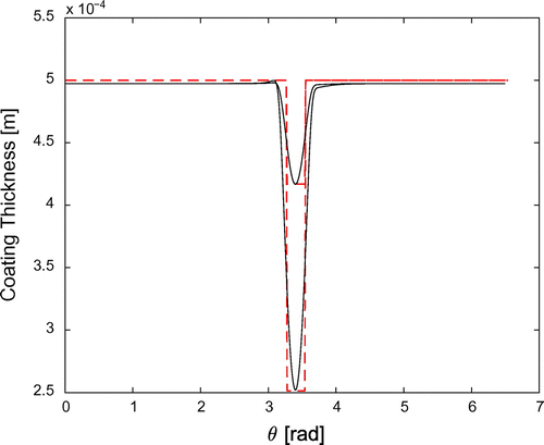
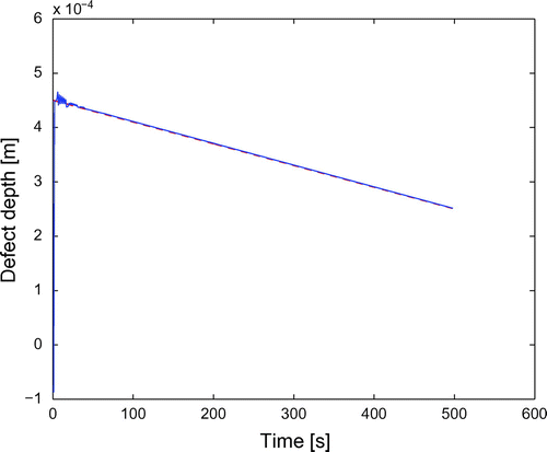
Figure shows the computed contrast at times 100 s and s. Figure compares the coating thickness reconstructed by means of the procedure describe in 3.1 (solid line) to the true thickness (red dashed line). Figure compares the time behaviour of the minimum of the reconstructed thickness (defect depth) with that of the true one.
Figure 2. Temperature contrast for constant velocity of the defect, at times 100 s (dashed line) and 600 s (solid line).
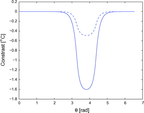
Figure 3. Thickness reconstruction for constant velocity of the defect, at times 100 s (upper lines) and 600 s (lower lines).
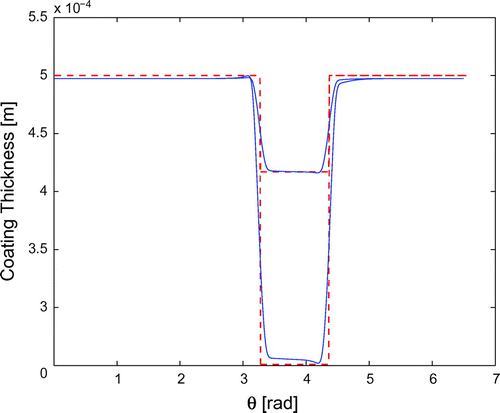
Figure 4. Time behaviour of the defect depth in the case of constant velocity: reconstructed (solid line), true (dashed, red line).
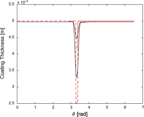
Figures , respectively, show the same quantities in the framework (2) of constant acceleration for the defect boundary, while Figures compute the contrast, reconstructed coating thickness and time behaviour of the coating depth in the framework (3) of sinusoidal velocity.
Figure 5. Temperature contrast for linear velocity of the defect, at times 100 s (dashed line) and 600 s (solid line).
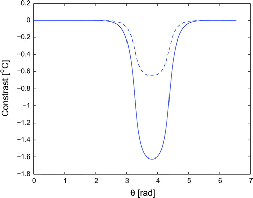
Figure 6. Thickness reconstruction for linear velocity of the defect, at times 100 s (upper lines) and 600 s (lower lines).
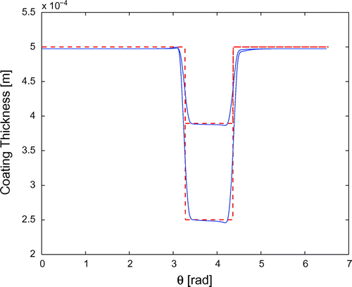
Figure 7. Time behaviour of the defect depth in the case of linear velocity: reconstructed (solid line), true (dashed, red line).
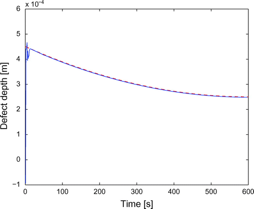
Figure 8. Temperature contrast for sinusoidal velocity of the defect, at times 100 s (dashed line) and 600 s (solid line).
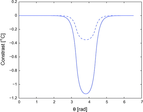
Figure 9. Thickness reconstruction for sinusoidal velocity of the defect, at times 100 s (upper lines) and 600 s (lower lines).
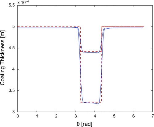
Figure 10. Time behaviour of the defect depth in the case of sinusoidal velocity: reconstructed (solid line), true (dashed, red line).
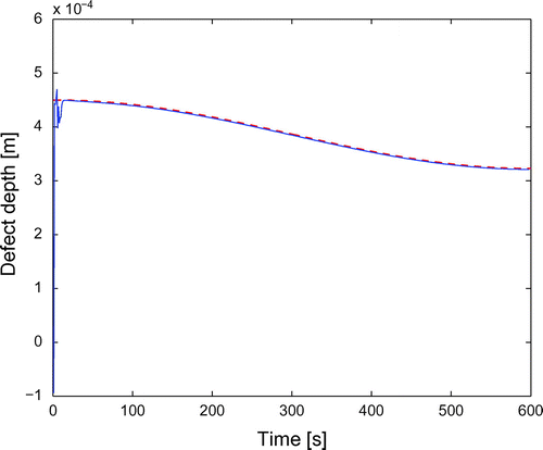
The reconstruction is very good for all three velocity profiles.
4.1. Goodness of the defect reconstruction
In the above simulations, the angular extension of the damage has been assumed . Using a fourth-order TPA, the reconstruction is very good down to
, as Figure , referring to a constant velocity, shows. Going to thinner extensions, the reconstruction slowly deteriorates: the position of the damage is properly detected also for an angle of
, but the damage depth is underestimated (see Figure ). A better reconstruction would require to increase the order of the TPA.
4.2. Evaluation of the error
For , consider the relative error
(25)
(25)
where is the coating thickness reconstructed by means of TPA expansion at order n (i.e. from (Equation10
(10)
(10) )):
(26)
(26)
where(27)
(27)
In Section 4, data are not affected by noise, so that is the truncation error, and assumed that the approximation scheme (in this case TPA) is correct, it converges to 0 for
.
Since measurements are naturally affected by noise, a more realistic form of our data is
where is a normal random variable with zero mean and standard deviation
.
We already noticed that, at least in our examples with simple defect geometries, the first few coefficients of the TPA expansion are enough to fit very well the unknown. The fact that the information about is contained mainly in the first coefficients
allows us to work with low values of k limiting in this way the effects of noise amplification.
Actually, noise is highly magnified for large n even when data have been smoothed. In fact, any given smoothing strategy is able to control the instability of numerical differentiation up to a corresponding order M. Since, in this case, smoothing is a typical regularization step, to increase M means to pay much in term of precision as can be seen in the specific literature (see for example [Citation24,Citation25]).
In our examples, even a small amount of noise makes the computation of terms for
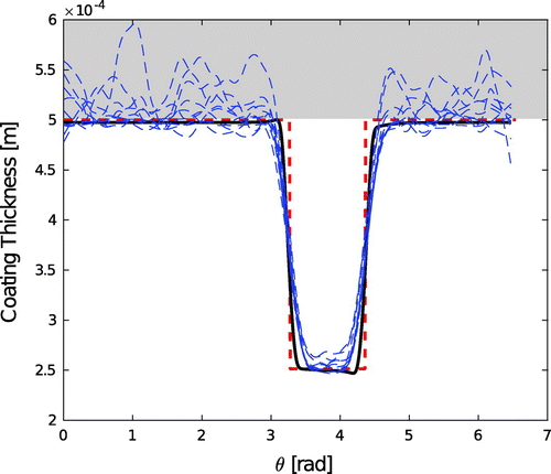
unnecessary. Smoothed reconstruction of the defects are shown in Figure for different values of the noise standard deviation.
Figure compares the reconstructed coating thickness for zero noise (thick solid line) to the true thickness (thick dashed line). The thin dashed lines refer to increasing up to 0.05 (see also Figure and relative discussion).
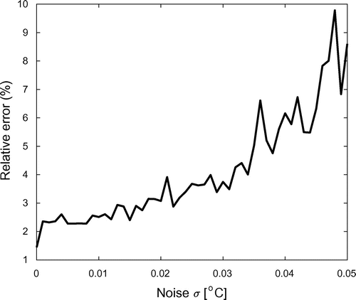
Figure shows the behaviour of for increasing
, where
is the standard deviation of a normal-distributed noise: a value of 0.03, corresponding to a
value of about
, is a typical figure for a thermal camera.
5. Conclusions
This paper deals with the problem of tracking the time evolution of hidden defects of the internal coating of a tube. This kind of problem arises when the coating degrades in the same time scale of data collection, and clearly it requires transient heat conduction modelling. We propose a linearization of the system that reduces the identification of an unknown domain (the damaged coating) to the identification of a boundary parameter (an effective heat transfer coefficient). Simulations are achieved with realistic materials, e.g. stainless steel tubes transporting water internally covered by FBE polymer, and meaningful environmental conditions. The results of the numerical tests reported in Section 4 are encouraging. The dependence of the reconstruction goodness on the measurement error is also investigated, showing that relative errors on the coating thickness lower than 10% can be expected with the typical noise levels of thermocamera devices.
6. Nomenclature
cylindrical tube (pipeline)
metallic shell of the pipeline
insulating shell (coating)
S cross section of
cross section of
cross section of
R internal radius of
a thickness of
thickness of the coating
thickness-to-radius ratio
internal heat transfer coefficient
internal temperature
external heat transfer coefficient
external temperature
effective heat transfer coefficient at
specific heat dissipated in
specific heat dissipated in
thermal conductivity of
thermal conductivity of
normalized conductivity
7. Acronyms
IBVP Initial Boundary Value Problem
TPA Thin Plate Approximation
FEM Finite Elements Method
FBE Fusion Bonded Epoxy
References
- Inglese G , Olmi R . Detecting longitudinal damages in the internal coating of a tube. Int J Heat Mass Transfer. 2018;116:1225–1236.
- Chantasiriwan S . Inverse heat conduction problem of determining time-dependent heat transfer coefficient Int J. Heat Mass Transf. 2000;42:4275–4285.
- Onyango TTM , Ingham DB , Lesnic D , et al . Determination of a time-dependent heat transfer coefficient from non-standard boundary measurements. Math Comput Simul. 2009;79:1577–1584.
- Su J , Hewitt GF . Inverse heat conductioon problem of estimating time-varying heat transfer coefficient. Numer Heat Transfer Part A. 2004;45:777–789.
- Kolodner II . Free boundary problem for the heat equation with applications to problems of change of phase. I general method of solution. Commun Pure Appl Math. 1956;IX:1–31.
- Shahgholian H , Chen G-Q , Luis Vazquez J , editors. Free boundary problems and related topics. Philos Trans R Soc A. 2015 sep;373.
- Knobloch E , Krechetnikov R . Problems on time-varying domains: formulation, dynamics and challenges. Acta Appl Math. 2015;137:123–157.
- Ng J , Aksikas I , Dubljevic S . Control of parabolic PDEs with time- varying spatial domain: Czochralski crystal growth process. Int J Control. 2013;86(9):1467–1478.
- Vuik C . Some historical notes about the Stefan problem. Nieuw Arch Wiskd. 1993;11:157–167.
- Chapiro G , Mazorche SR , Norman JH , et al. Solution of nonlinear parabolic problems using nonlinear complementarity algorithm (FDA-NCP). Mecanica Comput. 2010;XXIX:2141–2153.
- Van Bockstal K , Slodicka M . Determination of a time-dependent diffusivity in a nonlinear parabolic problem; 2014;23:307–330.
- Gulkac V . A numerical solution of the two-dimensional fusion problem with convective boundary conditions. Int J Comput Methods Eng Sci Mech. 2010;11(1):20–26.
- Novak IL , Slepchenko BM . A conservative algorithm for parabolic prolems in domains with moving boundaries. J Comput Phys. 2014;270:203–213.
- Hao DN , Thanh PX , Lesnic D . Determination of the heat transfer coefficients in transient heat conduction. Inverse Probl. 2013;29:1–21.
- Abdelhamid T , Elsheikh AH , Elazab A , et al. Simultaneous reconstruction of the time-dependent Robin coefficient and heat flux in heat conduction problems; 2017. DOI:10.1080/17415977.2017.1391243
- Burghold EM , Frekers Y , Kneer R . Determination of time-dependent thermal contact conductance through IR-thermography. Int J Therm Sci. 2015;98:148–155.
- Westbrook DR . Applications of asymptotic integration to potential problems for shells. SIAM J Appl Math. 1966;14(1):131–146.
- Kaup PG , Santosa F , Vogelius M . Method for imaging corrosion damage in thin plates from electrostatic data. Inverse Probl. 1996;12:279–293.
- Cleveland WS . Robust locally weighted regression and smoothing scatter-plots. J Amer Statist Assoc. 1979;74:829–836.
- Bergman TL , Lavine AS , Incropera FP , et al. Fundamentals of heat and mass transfer. New York (NY): Wiley; 2011.
- Winterton RHS . Where did the Dittus and Boelter equation come from? Int J Heat Mass Transfer. 1998;41:809–810.
- Coulson JM , Richardson JF . Chemical engineering. Vol. 1. Oxford: Butterworth-Heinemann; 1999.
- COMSOL Multiphysics® v. 5.2 . COMSOL AB, Stockholm, Sweden. Available from: http://www.comsol.com
- Murio DA . The mollification method and the numerical solution of ill-posed problems. New York (NY): Wiley; 1993.
- Bassey E , Whalley J , Sallis P . An evaluation of smoothing filters for gas sensor signal cleaning INFOCOMP. In: 2014: the Fourth International Conference on Advanced Communications and Computation; 2014. Paris (France).
Appendix 1
Formal derivation of (Equation11 (11)
(11)  (11) )
Let and
be the temperatures in
and
, respectively.
Assume that
and that
From the thinness of the coating, we have(A1)
(A1)
From the boundary condition (Equation3(3)
(3) ) in
, we have
(A2)
(A2) (
is the partial derivative of
w.r.t.
;
is supposed arbitrarily smooth in
, t and
) with
. Since
, we have
(A3)
(A3)
From the transmission condition for u and from the fundamental theorem of calculus, we have(A4)
(A4)
From the transmission condition for , we have
(A5)
(A5)
We set(A6)
(A6)
and, finally, write(A7)
(A7)
We introduce now the difference function(A8)
(A8)
defined in the domain which solves the IBVP
(A9)
(A9)
for ,
(A10)
(A10)
(A11)
(A11)
(A12)
(A12)
Since, , in each finite time interval the limit of
for
is zero. This is exactly (Equation11
(11)
(11) ).
Appendix 2
Technical aspects of the thin plate approximation
In what follows, is the normalized diffusivity. We plug the expansions (Equation20
(20)
(20) ) and (Equation21
(21)
(21) ) in the IBVP (Equation17
(17)
(17) )–(Equation19
(19)
(19) ) and obtain
(B1)
(B1)
(B2)
(B2)
(B3)
(B3)
and(B4)
(B4)
for .
Hence, the heat equation is transformed in
and, for ,
(B5)
(B5)
As for the boundary conditions, we have(B6)
(B6)
(B7)
(B7)
so that
and, for ,
so that(B8)
(B8)
In what follows, we calculate explicitly the first terms of the expansion. The terms of order four and five have been checked with MAPLE.
The starting point: order zero and one
The terms of order zero and one give the starting point of our iterative process.
We have
with so that
for all
. Similarly,
with and
. It means that also
is independent of z. Moreover, we assume
for so that
As a consequence we have .
Order two i.e. 

As for the order two, we have
and, consequently,(B9)
(B9)
Since is independent on z and
for
, we have
(B10)
(B10)
Order three i.e. 

Since , we have
(B11)
(B11)
Hence(B12)
(B12)
and(B13)
(B13)
Order four i.e. 

(B14)
(B14)
Order five i.e. 

(B15)
(B15)

