
 ?Mathematical formulae have been encoded as MathML and are displayed in this HTML version using MathJax in order to improve their display. Uncheck the box to turn MathJax off. This feature requires Javascript. Click on a formula to zoom.
ABSTRACT
A novel technique for the determination of local variations in the constituent level elastic parameters of fibre reinforced plastics composite plates has been presented from experimentally measured natural frequencies and mode shapes or frequency response functions (FRF) using finite element model updating technique. The constituent level elastic parameters, i.e. the fibre and matrix stiffnesses for a ‘patch area’ having different elastic properties from the rest of the structure have been estimated quantitatively. The location and extent of this patch can be predicted a-priori from careful comparison of mode shapes. The methodology uses the correlations between the experimentally measured frequencies and mode shapes or FRFs and their corresponding values from finite element predictions of the ‘patch plate’. The objective function, consisting of the weighted differences in the undamped eigenvalues as well as the normalized mode shapes or FRFs of the two models, is minimized in the least square sense using a gradient-based inverse eigen-sensitivity method implemented through a computer program. The methodology has been demonstrated through a numerically simulated example first, followed by a real experimental case study. Results indicated that the efficiency and the robustness of the algorithm depend upon the accuracy of the acquired modal data.
2010 MSC CLASSIFICATION:
Nomenclature
| = | Total error | |
| = | Error vectors for frequencies, mode shapes and FRFs, respectively | |
| = | Young’s moduli for fibre, fibre inside the patch and matrix, respectively | |
| = | Number of modes correlated | |
| = | Number of correlated modal coordinates | |
| = | Weight vectors for frequencies, mode shapes and FRFs, respectively | |
| = | Fibre volume ratio | |
| = | Poisson’s ratios for fibre outside the patch, fibre inside the patch and matrix, respectively | |
| = | Mass densities for fibre outside the patch, fibre inside the patch and matrix, respectively | |
| = | Experimentally measured and analytical mode-shape vectors, respectively | |
| = | Experimentally measured and analytical frequencies, respectively | |
| = | Measured and analytical FRFs, respectively |
Introduction
Fibre reinforced plastics (FRP) composite plates are being extensively used in high performance structures like aircrafts, missiles, space antennas, submersibles; in transportation industry applications like automobiles, etc. where weight saving is a major criterion without reduction of the stiffness. Recently, it has been inducted in infrastructure type of applications where instead of weight sensitivity the cost effectiveness and durability are more important [Citation1]. The predictability of dynamic behaviour of any structure is always very important from its performance and reliability point of view. Such dynamic behaviour is functions of material properties, geometry, boundary conditions and applied loading. Since the material and structural fabrication of FRP are one unified process and also due to the fact that curing techniques vary at places, the finally obtained material property parameters of the FRP structures may vary significantly from manufacturers’ specifications or from established standards. The average material properties of laminates can be determined by destructive quasi-static testing of samples, but such characterization tests are cumbersome for FRP type of anisotropic composites as the variables are large in number. It is even more difficult to carry out such characterization tests at the constituent level, i.e. at the fibre and matrix level, and the uncertainties associated with attainment of a target stiffness of the laminate still remains due to the fabrication and curing process. There is a genuine need that the actual existing material properties of laminated composite FRP structures must be determined accurately in-situ and in service conditions so that the dynamic performance of the structure can be assessed with confidence from time to time.
Alternative methodologies have been proposed in the literature to determine the average in-plane stiffness parameters of FRP composites from the vibration testing of actual structures using inverse approaches. Therein, the experimental dynamic responses are compared with the theoretical predictions and the analytical finite element model is updated by taking the uncertainties in the average material parameters to be the reason behind this discrepancy. Usually, the eigenfrequencies and mode-shapes are used as indicators in such updating methods. The concept of experimental modal testing and subsequent analysis [Citation2], where the applied force and resulting dynamic response of the structure can be measured simultaneously with precision, has been successfully used over decades to verify or correct finite element models. Lin [Citation3] has introduced a novel concept of a modal confidence factor (MCF) and a derived equivalent eigensystem based on the theoretical expansion of free decay response functions.
Correcting the finite element models by processing the dynamic test data to update the global parameters is an active area of research [Citation4,Citation5]. Usually, the algorithms are iterative but sometimes direct methods are also advocated. A direct system identification method based on the inverse solution of the equations of motion was introduced by Ghafory-Ashtiany et al. [Citation6] recently. Valuable early references of material parameter estimation in FRP type of composite structures using this model updating approach can be found with De Wilde et al. [Citation7], Sol [Citation8], Deobald and Gibson [Citation9], Moussu and Nivoit [Citation10], Grediac and Paris [Citation11], Frederiksen [Citation12] and Larsson [Citation13], etc. Therein the focus of attention was to estimate mainly the in-plane average elastic constants viz. ,
,
and
of orthotropic materials using model updating techniques, even in presence of elastic boundaries [Citation14]. Out-of-plane elastic constants have also been estimated as indicated in some references [Citation15]. Primarily, sensitivity-based inverse eigensensitivity [Citation16] type of algorithms were used; although evolutionary algorithms such as genetic algorithm have also been tried [Citation17]. Dascotte [Citation18] applied the inverse eigensensitivity technique to estimate the in-plane elastic constants of vertically stiffened composite cylindrical shells using frequency and mode-shape information. Almost all early references relied upon frequencies and mode shapes information for the estimation. Directly measured FRFs were also used as indicators sometimes [Citation19–21] to estimate global average parameters or to detect damages. Much insight can be obtained from the work of Doebling and Farrar [Citation22] about the statistical distributions of modal parameters identified from averaged FRFs which can be employed for model correlation and damage identification. Yesilyurt and Gursoy [Citation23] reported the determination of average elastic constants and modal damping ratios of a unidirectional composite beam.
For FRP type of a structure, it would be more appropriate if the structure can be tested as a whole to determine its constituent level properties in-situ, and not the averaged elastic properties alone so that all the subsequent analysis would be much more realistic. In this regard, an ultrasonic bulk-wave technique was adopted by Chu and Rokhlin [Citation24] for measuring the effective elastic constants of silicon-carbide fibres bonded in silicon-nitride matrix composite. Mishra and Chakraborty [Citation25,Citation26] have attempted to estimate the elastic properties of constituent fibre and matrix of a unidirectionally reinforced FRP plate. However, these studies have not considered any local variations of properties within the structure. But in reality, a large proportion of fabrication of such structures is still being done through hand lay-up type of labour intensive processes, wherein variations of properties within the structure are usually present. This affects the dynamic responses at global level considerably. Hence, it would be better if such regions or ‘patches’ having different properties can be identified accurately and their elastic properties are estimated precisely so as to decide whether the FRP structure as a whole can still perform satisfactorily. It is even more useful if such determination can be carried out non-destructively. Although there has been tremendous improvement in analysis capability using established finite element software, this alone cannot guarantee the reliable prediction of the overall dynamic behaviour of structures. This is so because of the fact that the error comes from material property variations, especially if such variation is confined to a region large enough to affect the overall dynamics. Unless this local variation of material property is tackled efficiently, the current state-of-the-art of model updating cannot provide an accurate solution to the prediction of global dynamic behaviour using any inverse approach. Current model updating techniques need to pay attention to this obvious and realistic picture of the manufacturing process of FRP type of materials wherein local variation of elastic properties is very probable. Literature related to such determination of local variations of elastic properties using inverse approach is still perhaps non-existent.
Determination of average elastic parameters of FRP type of composites with unidirectionally or randomly oriented fibres embedded in matrix always poses a challenge to the engineers dealing with micromechanics. Analytical approaches in micromechanics aspire to achieve the same goal of finding the average material property parameters to be defined in terms of constitutive material constants and reinforcing efficiency of the fibres. Most popular concept among them is the self consistent fibre-matrix model by Halpin and Tsai [Citation27], where a general formula to determine various material elastic constants using an equation has been presented. The experimentally determined coefficient , which basically is the reinforcing efficiency of the fibres, is the backbone of this methodology. The effort is concentrated on the effective global average elastic modulus of composite materials and do not address any local variations. Halpin and Kardos [Citation28] revisited this popular methodology and reaffirmed that upto a volume fraction of 70% Halpin–Tsai equations give good approximation of all the elastic parameters. It is to be mentioned that such a model eventually requires characterization tests to be performed at the constituent level which is even more challenging and very time consuming due to the complexity in preparation of samples for fibres and matrix. Moreover, such characteristic values may have considerable variations in actual practice. If the fibre and matrix property vary significantly at the local level, it can induce gross error in the determination of global dynamic properties at the structural level.
Although looks similar in spirit, the change in stiffness of a composite structure due to the presence of deliberate foreign inclusions is actually different from the current investigation. Inclusions as foreign bodies in matrix type of material are expected to take very small space and are unlikely to affect the global dynamics. Sometimes, these inclusions are deliberately used to strengthen or stiffen the structures and are present in regular patterns.
Another popular research area is structural damage detection using vibration test data [Citation29], but the focus of attention there is to detect physical discontinuity from the vibration signature of the otherwise homogeneous continuous medium. The degradation of elastic properties of the entire structure in such a problem may be severe and may be of concern for the integrity of the structure, even if material parameters may not vary significantly over the region. The current problem is completely different in this respect.
An attempt has been made in this regard to address a problem where material elastic properties vary locally in FRP type of structure as a result of limitations in quality control. The level of variations in stiffness due to the limitation in fabrication quality control (e.g. presence of a small ‘damaged’ part in a roll of fibres used for fabricating FRP composite) is actually much less than that is witnessed in any damages. Even then the variation is sufficient enough to cause differences in global dynamical properties and thus may affect the performance. A novel method using finite element model updating technique for the quantification of the local variation in material elastic properties at the constituent level, viz. fibre and matrix of a laminated unidirectional composite plate type of structure, has been implemented. The local variation has been realized through a ‘patch’ with different elastic property for the embedded fibres. If fairly accurate measurements for the global dynamic responses are made available through modal testing and subsequent analysis, it may be possible to determine the accurate material constants for a patch of composite having material constants different from the rest of the plate by solving an inverse problem. The location and extent of the patch are to be determined first from the observations of anomalies in mode shapes as compared to mode shapes of a finite element reference plate without such patch. Unexpected local variations in mode-shape coordinates can identify a broad ‘patch area’ within which the structure has a local variation of stiffness. It is to be mentioned here that frequencies alone cannot locate such regional changes, use of mode shapes are mandatory in this regard. There are established methodologies related to localization of damage [Citation30,Citation31] which look similar in spirit to the present investigation. But the current investigation is indeed different as it focuses more on the quantification of such local variations in elastic properties, assuming that the localization of ‘patch’ has already been performed. The method is based on the minimization of the sum of the differences in the modal properties (i.e. eigenfrequencies and mode shapes or FRFs) between the predicted values from the finite element analysis and those as determined experimentally. Frequencies and mode shapes are primarily chosen here as they are the most stable global dynamic responses for which established related hardware and software are available. Moreover, unlike FRFs the frequencies and normal mode shapes are little affected by damping. The scope of the work includes a thorough investigation on a numerically simulated problem first to identify the level of difficulties such a novel technique may face. Particular attention has been given to the effects of random noise on the estimated parameters for this simulated problem. Actual experiment has also been conducted on a fabricated unidirectional FRP rectangular plate to observe the efficiency of the algorithm. The identification of the fibre elastic properties of a patch, using the gradient-based inverse eigensensitivity method (IEM), has been implemented taking the measured natural frequencies and mode shapes or FRFs as the basis for updating. The developed programme gives flexibility to the user the incorporation of any preference towards the selective inclusion of particular mode-shape coordinate and frequency data, which the commercial software may permit but will be difficult to control. In case FRFs are used as indicators, especially when the effects of patch elastic parameters are localized to a small region, the IEM method is implemented using FEMtools [Citation32]. The scope of the work includes the verification of the performance of the algorithm under the condition of modal and coordinate sparsity. Damping has been considered to be small for the present investigation. In this proof of concept study, the application is restricted to only a single patch area having local differences in the elastic properties. If there is no substantial variation in the local properties within this ‘patch’ as compared to the rest of the structure, the algorithm is noted to be able to ascertain that as well.
Finite element modelling of the FRP plates
An eight noded linear solid element (C3D8R) has been used in ABAQUS [Citation33] to model the rectangular plate. A two noded truss element (T3D2) is embedded into the solid element to model the reinforcing fibres with perfect bond between them. A shifted Blocked Lanczos algorithm is used to determine the undamped modal properties, i.e. the natural frequencies and mode shapes of the structure. The FRFs are generated by mode superposition method, considering a large number of modes to achieve required accuracy. The ‘patch’ is modelled using a different elastic property for the embedded fibres but the matrix property has been considered the same for the entire plate. This proposition is much consistent with the hand layup type of fabrication process.
Numerical simulation of experimental data
The first problem in this investigation is a numerically simulated one. The numerically simulated ‘experimental data’ has been generated using the same finite element model as described above and involving a set of ‘reference’ material constants chosen realistically (believed to be determined from the real characterization tests in actual experiments). The geometry and mass density are assumed to be accurately determined and the boundary conditions are assumed to be free-free only. Eigensolutions and subsequent mode superposition to generate simulated FRFs is considered as substitute for real modal test and the FRFs thus obtained has been termed as ‘experimental’. ‘Noisy experimental data’ are generated by adding uniformly distributed random noise to these ‘experimental’ reference frequencies along with mode shapes or FRFs.
Subsequently, the investigation also contains a real experimental case study where the FRFs are directly measured and the modal properties are extracted by modal analysis.
Formation of objective functions
The objective function is the weighted summation of error in natural frequencies and mode shapes or FRFs, provided the numerical and experimental modes or FRFs are correctly paired through any appropriate criteria. The mode shapes are paired through Modal Assurance Criteria [Citation2] (MAC) which is a measure of the similarity between two modal vectors. The FRFs are paired using Cross Signature Assurance Criteria (CSAC) and Cross Signature Scale Factor [Citation34] (CSF). The total error term is then
(1)
(1)
Here, the frequency error function is
(2)
(2)
The mode-shape error function is
(3)
(3)
and the FRF error function is
(4)
(4)
The error terms of frequencies, mode shapes and FRFs can be individually weighted in this currently developed algorithm depending upon the confidence the user has on them. However, only a limited number of degrees of freedom, which can be measured realistically in actual tests, are picked from the analytical mode shapes or FRFs and paired with corresponding experimental ones [Citation35].
Estimation of parameters
The first step in the estimation of parameters is to correctly identify those parameters which are responsible for the discrepancies in global dynamic responses. Usually, an exhaustive search of all possible parameter sets should be made and a subset of these parameters need to be selected by eliminating either less sensitive parameters, or selecting parameters with a high level of uncertainties. The first part of the present investigation being a numerically simulated example, the constitutive level material parameters, i.e. the fibre and matrix elastic constants, both for the ‘patch’ area and for the rest of the plate are ‘made’ to create that difference between the numerically simulated ‘experimental’ and the finite element modal or FRF databases. The question of searching for appropriate parameters does not arise in this case. Anyway, a sensitivity analysis of the frequencies with respect to the selected parameters, namely the elastic constant of the fibres of the ‘patch’, elastic constants of fibres for the rest of the plate and the elastic constant of the matrix has been carried out by choosing a set of reference parameter values. Finite element analysis was performed to determine the eigenfrequencies and eigenvectors and there from the FRFs, with respect to these base parameters. Then each parameter was increased from its reference value by 10% in turn and a new finite element analysis was carried out. The normalized values of increased frequency and mode shapes or FRFs are the relative sensitivities for that parameter at that mode [13].
For the real experimental case study, a ‘patch’ has been created within an FRP plate having 15 layers with every alternate reinforcing mats removed within the patch area during fabrication, creating considerable local changes to the stiffness there. In the inverse problem, such changes can be detected if its global dynamic responses, i.e. the changes in frequencies and mode shapes or FRFs can be sensed by real hardware even in presence of a usual level of measurement noise. This is possible when effects of other factors, such as slight non-homogeneity of the dispersed matrix, minor geometrical variations of the laminate etc are much less in degree as compared to this major effect of changes of the stiffness of the laminate within the patch due to the removal of fibres. All these factors, including some inevitable experimental errors may contribute to slight variations in estimated parameters.
This is the reason for selection of the constituent level elastic parameters as the dominant variables for updating in this present investigation. Although local variations into the elastic properties of the FRP plate can be attributed to the variation in either matrix elastic property or fibre elastic property or both, in most cases the stiffness contribution of fibres is substantial as compared to that of the matrix. Thus the changes in a local elastic constant of the FRP composite is realized by the algorithm as if the rectangular plate is having a ‘patch’ with the different elastic property of fibres only in that region. The physical reason may be the presence of ineffective fibres due to debonding or breakage and have been realized here equivalently through the changes in the elastic property of the embedded fibres within this patch. It needs to be clarified that still, this is a sort of equivalence only. When there will be changes in matrix elastic properties, even then the current algorithm can take care of that in the same way. In order to distinguish the changes in matrix elastic properties from that of the changes in fibre elastic properties locally within a patch, the number of parameters to be tackled will increase. To solve such problem with the same accuracy level, the number of available information needs to be increased by including more number of modes or measurable coordinates of mode shapes or FRFs or their combinations This can be possible in real experiments by changing the excitation mechanism to something more effective (e.g. by using steel tip instead of rubber tip in impact hammer or by using modal shaker) to increase the signal-to-noise ratio.
The proposed algorithm requires initial guesses for the parameters to start the iteration which is done by generating uniformly distributed random values for the parameters within the selected bounds. The bounds have been chosen from the established standards considering the statistical variances of the parameters and their nominal values. For any practical situation, the bounds need not necessarily be widely apart, but this will largely depend upon the a-priori information the user is having.
Numerical implementation of the proposed methodology
The sensitivity-based IEM [Citation36] has been adopted for the parameter identification. The linearized first order approximation of the relationship between measurable (output) eigenvalues and eigenvectors or FRFs and (input) constitutive level material parameters, including that of the ‘patch’ can be represented through a Taylor series approximation
(4)
(4)
where
represent the parameters to be identified (i.e. the elastic properties of fibres, matrix and elastic properties of fibres within the ‘patch’),
are the a-priori estimates of
= measured eigenvalues and eigenvectors or FRFs of the plate
= modal properties of initial finite element model of the plate
= first order sensitivity matrix (Jacobian matrix), of eigenvalues and eigenvectors or FRFs of the plate with respect to the parameters to be estimated.
The above Equation (4) can be expressed in brief
(5)
(5)
where
,
, and
In expanded and normalized form the equation will look like –
(6)
(6)
The residual error vector at any iteration is
(7)
(7)
The IEM tries to minimize the above error function in weighted least square sense, thereby suggesting change to the parameter
A new is generated at each iteration using
(8)
(8)
The procedure is repeated with updated constituent material parameter values, until the square of the error between the analytical and numerically simulated ‘experimental’ modes falls within a predetermined margin of error
.
(9)
(9)
The stiffness and mass matrices are updated before a new eigensolution is computed. The algorithm has been implemented through a coupled C++ programme/FEMtools and ABAQUS code and is explained in . ABAQUS is called by the written programme whenever there is an eigensolution needed. FEMtools uses a Bayesian approach to compute the weighting matrices, whereas the user defined programme controls the weights directly. However, they implement exactly the same IEM approach.
Figure 1. Flowchart of the optimization algorithm.
The process of identification is restricted in its present form to rectangular plate and rectangular patch area only. The procedure of locating the existence of a patch area having different elastic properties of constituent materials is performed first by observation of first six mode shapes of the reference plate and actual plate with patch. For the real experimental case study, a reference plate is also fabricated without the presence of a patch to have a realistic comparison and as a proof of concept, although the same task could have been performed using a finite element model, but with less reliability.
Numerically simulated example: estimation of elastic parameters of fibre, matrix and ‘patch’ of a rectangular FRP plate
An FRP plate of 400 mm length, 300 mm width and 8 mm thickness has been selected for the current numerically simulated case studies. In this proof of concept, the aspect ratio of the plate has been chosen in such a way so as to avoid repeated or very close modes. The overall material properties assumed for this test plate have been presented in . In real experiments, these values are supposed to be determined from material characterization tests. Altogether eight layers or plies have been assumed. Finite element model with a converged mesh was adopted to model the plate with a patch of size 120 mm × 100 mm (10% of the plate area). The patch is located asymmetrically within the rectangular domain in an arbitrary location, so as to affect most of its modes and avoid nodal points. If in a practical situation, the patch falls onto a node point, that particular mode should be restricted from participating into the iterative optimization process due to lack of sensitivity. The size of the patch is also varied in one case. Eigensolution of the finite element model generated the numerically simulated ‘experimental’ frequencies and mode shapes. FRFs at selected locations are synthesized using modal superposition, considering a large number of modes. The first six numerically simulated ‘experimental’ frequencies in free-free boundary conditions are shown in . The mode shapes are not shown for brevity.
Table 1. Material properties for the test plate.
Table 2. First six natural frequencies of the ‘patch’ plate.
The inverse problem has now been tried to observe if these material elastic parameters, including that of the ‘patch’ modulus can be quantified accurately from the arbitrarily chosen initial guesses through the application of IEM algorithm.
Parameter estimation has been attempted for both the cases–fibre inside the ‘patch’ having a higher elastic constant than the rest of the plate and vice versa. The first case is realistic if a repair work is done as a patch in an existing FRP panel and the task is to verify the stiffness achieved. The second one is replicating a damage scenario. To test the robustness of the algorithm, the same value of elastic constant for the fibres within the patch and in the rest of plate has been assumed and as expected, the algorithm confirmed that the plate is uniform in terms of global elastic properties and the patch selected is no different from the rest of the plate. This is to be mentioned that the existence and location of such patch with significantly different elastic properties can easily be detected by observing changes of curvatures of either the mode shapes or the FRFs. The primary focus of attention of the present investigation being the quantification of the elastic stiffness of such detected patches, determining the location and extent of such patches are not discussed here.
The efficacy of the algorithm needs also to be established for the inevitable modal and spatial incompleteness encountered in practice. Only a few selected degrees of freedom of the mode shapes which are more sensitive are used to correlate the experimental model and the finite element predictions. The present investigation selectively uses modes from among the first 10 modes.
The differences in frequencies of a few selected modes of the example plate with and without the ‘patch’ are presented in . It is perceptible that a few frequencies have noticeable difference which may be detectable in real measurements. It can also be noted that these differences will increase as the patch area increases or the elastic modulus of fibres within patch area differs substantially from the rest of the plate.
Table 3. Difference in frequencies of an example plate with and without the presence of a ‘patch’.
The algorithm has been tried from a large number of initial values within wide limits of upper and lower bounds, but for brevity, only a few have been plotted to show the convergences. Both noise free and with random noise cases have been investigated and compared to get a feeling of the effects of random noise on the results obtained. The present algorithm is found to be flexible in terms of selective use of mode-shape coordinates and in terms of adjustments of penalty functions through weights.
The effects of random noise, step size in optimization algorithm, size and position of the patch and the advantage of having FRF information in the objective function, in place of mode-shape information, are major critical factors for successful implementation of the algorithm. They are discussed here in sequence.
Effects of random noise
It is observed that the convergence for the elastic parameters, i.e. ,
and
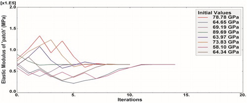
from even widely scattered initial values is mostly monotonic and occurs within a few iterations if the numerically simulated ‘experimental data’ is noise free. They are depicted in . The time of convergence increases substantially if the experimental data is polluted with random noise (e.g. ±0.5% for the modal frequencies and upto ±5% for the mode-shape vectors). The convergence for this case has been shown in for various initial values of the parameters. It is to be noted that the level of random noise considered here is somewhat comparable with that expected in the actual modal testing of similar structures in unfavourable conditions. The uniqueness of the results remained unaffected.
Figure 2. Convergence plots for (a) fibre, (b) matrix and (c) ‘patch’ moduli without noise in ‘test’ data.
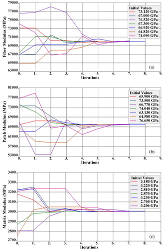
Figure 3. Convergence plots for (a) fibre, (b) matrix and (c) ‘patch’ moduli with noise in ‘test’ data.
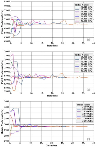
The algorithm has been tested for even higher level of random noises (±1% for the modal frequencies and upto ±10% for the mode-shape vectors). It has been observed that global fibre modulus and the matrix modulus is still uniquely estimated, although the number of iterations increased substantially. The patch modulus in most cases converged to values with higher variations. It appears that the local information about the changes in the elastic modulus of the fibres within the patch through mode-shape coordinates is subsided by the effects of noise. Since natural frequencies and mode shapes both are normalized global indicators of dynamic responses, local information such as differences in elastic properties within a small patch is easily smeared and lost due to noise. If the primary aim in a modal test is to just correlate the experimental modes with the corresponding theoretical modes, even higher level of noise can also be permissible.
Effect of the choice of step size for parameters
The choice of step size is always a determining factor for the nature of convergence in the inverse eigensensitivity type of gradient-based optimization algorithms and there are no definitive guidelines for selecting the step size yet and it largely depends upon the judgement of the user. It has been observed in the present example that a larger step size sometimes result in divergence of the estimated parameters. If the step size is not sufficiently small but still within limit, it results into oscillatory behaviour of the convergence, but the uniqueness of the results may not suffer. An optimum step size at present seems to be problem dependent and a general recommendation was not possible to be made through the lessions learnt from the existing problem. A broad guideline could be to restrict the maximum step size within 30% of the parameter values, considering even the oscillatory behaviour of the algorithm. The best option is to have a few trial runs of the algorithm and select the minimum step sizes judiciously, to avoid unncessarily delay in convergence.
The existing algorithm permits use of different step sizes at each iteration to have better control over convergence, but at present instead of an automatic adaptive process, manual intervention is required to implement the same. If the programme is observed to be running slow, an increase in step size for that particular variable may be beneficial but may be detrimental to the other parameters. For example, the ‘local’ patch modulus is observed to be converging very slowly sometimes, as compared to the other ‘global’ elastic fibre and matrix modulus. It is to be mentioned that such adjustments of step sizes adaptively is observed to be very tedious, favourable results are not guaranteed, rather it will be more hopeful for future application of such algorithm to choose a local indicator in objective function, such as a frequency response function to increase the rate of convergence of local parameters.
Effect of the size of ‘patch’
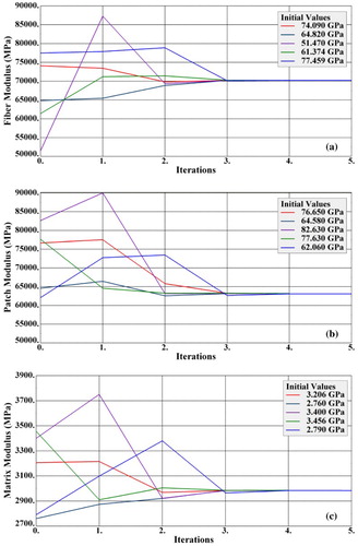
It has been observed that the algorithm performs better with a larger patch as the difference in modal parameters for the numerically simulated ‘experimental’ model and the finite element model will be larger and easily detectable. shows the convergence curves of the elastic parameters with a patch size covering 20% of the plate area. It is apparent that the convergence is achieved rapidly as compared to a patch area of 10% shown earlier. It has been observed in general, that for very small patches with relatively small difference in material properties, the algorithm becomes dependent upon the difference in those most sensitive regions of mode shapes. This puts a high demand that the mode-shape data are acquired as accurately as possible, at least at those designated locations. When tested with a patch area of 5% of the plate, the algorithm was able to estimate the patch modulus but only with a large variation (approximately 10%).
Figure 4. Convergence plots for (a) fibre, (b) matrix and (c) ‘patch’ moduli with a 20% sized patch and having noise in ‘test’ data.
Effect of the position of patch
The current algorithm uses the frequencies and mode-shape information only as indicators to detect changes in fibre elastic modulus of the patch, along with the global elastic modulus of fibre and matrix. The objective function must contain sufficient number of mode-shape coordinates which are affected by the patch location substantially. Since the algorithm uses a gradient-based optimization technique, if the patch is situated at any node point of a particular mode, the sensitivity matrix will become ill conditioned. The nodal points of those modes are to be carefully observed and corresponding degrees of freedoms should not be allowed to participate in updating process due to lack of sensitivity. Thus the algorithm cannot be fully automatic and user intervention is desirable whenever appropriate. In the present proof of concept study, the patch is strategically located in a position so as to affect most of the modes.
Use of FRF information in place of mode-shape information in the objective function
The algorithm has now been implemented, using the FRF information, for multiple parameters: the elastic modulus of fibres within the patch and the elastic modulus of fibres and matrix for the rest of the plate globally. This is the most practical situation where matrix is dispersed uniformly during fabrication anyway but fibre mats were already damaged locally. Both noise free and with random noise, cases have been investigated, but the investigations with noise only are reported. The ‘numerically simulated experimental’ modal and FRF databases for this case are generated for a ‘patch’ modulus of 66 GPa. It is observed that the convergences for ,
and
from even widely scattered initial values are mostly monotonic. The inclusion of noise is observed only to delay the convergence, without affecting the uniqueness. Moreover, since there is a combination of local and global parameters, using only FRFs have delayed the convergence further but the uniqueness was ultimately preserved. The convergence curve for only the patch is shown in .
Figure 5. Convergence of ‘patch’ moduli with noise in ‘test’ data.
The necessity to include the global responses under such conditions was investigated by attempting the parameter estimation by defining the objective function consisting of frequencies as well as FRFs. presents the convergence curves for the ‘patch’ under the influence of random noise (0.1% in frequencies and 1% in FRFs) for the combination of frequencies and FRFs. It has been observed that the incorporation of global information such as frequency has improved the convergence of global properties such as the overall fibre and matrix properties of the plate. However, the convergence of the elastic properties of the fibres within the patch has not significantly improved as shown in . Ultimately all the three parameters converged uniquely.
Figure 6. Convergence of the ‘patch’ modulus with noise in ‘test’ data using frequency and FRFs.
In fact, by attempting the inverse eigensensitivity algorithm to estimate the global fibre and matrix elastic property and the elastic property of the fibres within the patch using both frequency and FRF information, the user can easily monitor the convergence criteria to identify whether the contribution of the local patch parameter is substantial. If the effect of such local variation is obvious, then the algorithm can be run more efficiently in two stages: first the global elastic parameters can be approximately updated using frequency only, and subsequently, the algorithm may be tried with FRF information alone to update the patch parameter. This will be a much faster approach rather than combining the FRF and frequencies from the very beginning. It is to be mentioned that the inverse algorithm, implemented here, selects the weights to be used along with different parts of the objective functions from Bayesian estimate. User intervention for manually adjusting these weights in favour of rapid convergence is desirable but this largely depends upon the judicious decision on the part of the user.
It may be concluded that when there is a substantial local variation in elastic properties, the FRFs play a greater role, whereas, if the elastic properties of the rest of the plate have substantial contribution to global dynamical responses, the inclusion of global frequency information will be more desirable.
Experimental case study: estimation of elastic parameters of fibre, matrix and ‘patch’ of a fabricated rectangular FRP plate
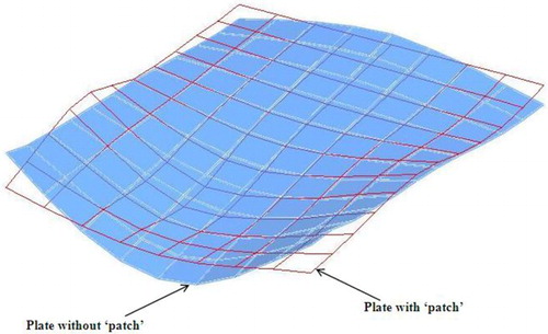
To investigate the performance of the suggested methodology for determining constituent level elastic parameters of actual FRP composite plates with patch using frequencies and mode shapes, 2 similar unidirectional FRP plates of sizes 384 mm × 290 mm and consisting of 15 layers of fibre mats were fabricated using the hand lay-up process. One of the plates is having a weak spot in terms of stiffness called a ‘patch’ of size 120 mm × 100 mm where alternate layers of unidirectional fibres (altogether seven layers) were removed, thereby creating a zone of reduced stiffness resulting from lower fibre volume ratio. The location and orientation of this ‘patch’ are shown in . The fibre direction was parallel to the shorter side of the plate. Another ‘reference plate’ of exactly the same dimensions and material properties was also fabricated, the sole purpose of which was to have a comparison of the frequencies and mode shapes with the ‘patch plate’ to assess qualitatively the special features associated with the patch. Unidirectional E-Glass fibre mats of 343 GSM (grams per square metres) were used to fabricate the plates. Epoxy resin EPICOTE828, hardener EPICURE and curing agent EPIKURE101 were used to prepare the matrix EPON3002. The final thickness obtained was measured to be 6.03 mm for the patch plate, whereas the reference plate was 5.91 mm thick. The fabricated plates were hot cured at 130°C for 12 h and an approximate pressure of 10.5 ton/m2 was maintained during the curing. Subsequently, the plates were cured again at room temperature for another 12 h. Teflon sheets were used at the top as well as at the bottom surfaces during the fabrication so as to facilitate de-moulding. Both the plates were cast slightly oversized to avoid the obvious non-homogeneity at the boundaries. The plates were cut to the exact dimensions with the help of an abrasive particle cutter to obtain smooth boundaries.
Figure 7. Dimensions of the test plate with a ‘patch’ having different elastic properties.
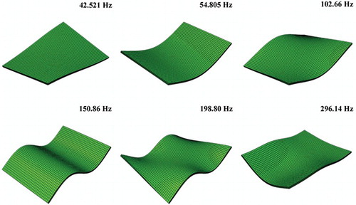
Both the FRP plates were modal tested under free-free boundary conditions using impact excitation with an instrumented hammer with a force transducer IEPE 8206-002 [Citation37] and the responses were picked up by DeltaTron 4507 IEPE accelerometer [Citation37] at a selected point. Altogether 108 excitation points were used for measuring the frequency response functions from which the natural frequencies and modes shapes were extracted using ME’Scope VES modal analysis software [Citation38]. It may be noted that, in order to avoid the smoothening effect on the mode shapes imparted by the adopted modal analysis software, the spatial resolution has been kept sufficiently high. From the recorded force auto spectrum and the coherence functions, it was apparent that at least upto five modes the quality of measurement was excellent and thus this range can confidently be considered for updating using frequencies and mode shapes. The sixth mode was also measured with moderate accuracy and can be used with less weight in objective function. The measured natural frequencies for the first six modes of the ‘patch plate’ as well as of the reference plate are shown in . The corresponding six mode shapes of the two plates are shown in .
Table 4. Natural frequencies of the ‘patch’ plate and the reference plate.
Figure 8. Measured mode shapes of the ‘patch’ plate and the reference plate.
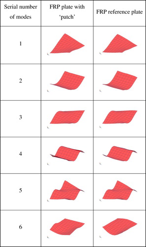
From it is immediately apparent that substantial difference exists between the measured sixth natural frequencies of the two plates. The 6th mode shapes of the ‘patch’ plate and the reference plate are overlaid in for better visualization. The softening effect of the reduced modulus within the patch which makes the structure more flexible is very clear from the comparison. This can more conveniently be done for complicated structures by superposing the animations of the mode shapes and is an effective tool for identification of the location of such patches. It is to be re-emphasized that in practical situation there would not be any such reference plate actually fabricated to compare the results with, the user needs to use finite element model to realize any such ‘reference behaviour’.
Figure 9. Comparison of mode 6 for the plates with and without ‘patch’.
The next step in the model updating procedure using frequency and mode-shape information is a detailed and converged finite element modelling of the FRP patch plate. This is done using the same eight noded linear solid elements (C3D8R) for the matrix and two noded truss elements (T3D2) for the embedded fibres. The frequencies and mode shapes were computed using a shifted Blocked Lanczos algorithm as explained earlier. The initial values of the elastic parameters were taken from standard handbooks or from manufacturers’ manual. The matrix property was assumed to be uniform throughout the plate and the reduced stiffness within the ‘patch’ was represented by a reduced elastic modulus of the reinforcing fibres. A typical set of frequencies and mode shapes from the FE analysis of the patch plate corresponding to an initial set of material constants are shown in .
Figure 10. Computed FE mode shapes of the ‘patch plate’.
The first step in model updating is a selection of appropriate parameters to be updated. Unlike the numerically simulated problems, effects of geometrical imperfections and material non-homogeneity etc. will eventually pervade the results, even for an apparently smooth finished plate. But in the present case study, it appeared that the plates were geometrically uniform and homogeneous and from visual inspection, no major local defects were observed. Considering the above facts, the overall matrix elastic modulus and the average fibre modulus were selected as global parameters to be updated. In addition to the above global parameters, the elastic modulus of the fibres within the patch was also selected as the local parameter to be updated. The model updating exercise was carried out then using the programme implementing the IEM, keeping track of the correlation between the numerical and experimental modes using modal assurance criteria (MAC) at each step of iteration from a large number of initial values of the above parameters. It is to be mentioned here that for FRP structures due to the varying stiffnesses in two orthogonal directions during the course of iterations, the experimental modes may not always pair sequentially with the analytical modes. Such algorithms must have provisions for the correct pairing of corresponding modes at each step of iteration by establishing proper correlation between experimental and analytical modes through MAC type of correlations. The current programme can efficiently tackle this ‘mode flipping’ behaviour.
While implementing the algorithm using frequency and mode shape information, first six modes were initially used for identification, of which the first five modes contributed most towards the convergence of the global matrix and global fibre modulus. These two parameters were estimated in a robust manner, especially the matrix value which was estimated to be 1.69 GPa, Similar observations were made using FRF data. This is substantially lower than its nominal value of 3.53 GPa mentioned in manufacturer’s datasheet. The tested elastic modulus of a similar matrix sample is found to be 1.34 GPa. Thus the updated matrix modulus was mostly to be believed rather than the manufacturer’s supplied data or one scanty data from the static test. The updated global fibre modulus was having somewhat a larger variation, between 78 and 83 GPa. While using FRF data, the range of estimated global fibre modulus slightly widened to 75–88 GPa, indicating that use of FRF could not be much beneficial for this parameter. The patch modulus was not estimated consistently using mode-shape information. Even using FRF information, the variation was quite large, between 65 and 33 GPa. To investigate such behaviour of the algorithm, the sensitivity of the modes with respect to the patch modulus was referred. It was immediately apparent that unless the 6th, 10th and 11th modes can be measured with sufficient accuracy, the determination of the patch parameter may not be unique. Since in the current investigation it was not possible to measure beyond 6th mode with the required accuracy, the higher experimental frequencies and mode shapes needed to be supplemented from numerical simulations, provided all lower observed modes are perfectly matched. For this reason, the manufacturer’s manual was consulted. The nominal value of fibre elastic modulus was found to be 80 GPa which is consistent with the updated results so far. Since 7 layers of the unidirectional fibre mats were removed out of total 15 layers, the elastic modulus of the ‘patch’ area was guessed to be around 50 GPa. With these two moduli of fibres and taking the updated value of matrix modulus to be correct, i.e. 1.69 GPa, the whole ranges of frequencies and mode shapes and FRFs were regenerated. The model was fine tuned so that the first five modes matched exactly to the observed values. The 6th mode had slight variations in frequency but the mode shape correlates exactly. Since none of the higher modes could be measured, there was nothing to compare the results with for the modes ranging between 7th and 11th modes. In fact, two more sensitive modes in the higher frequency ranges beyond 6th mode, viz. the 10th and 11th modes were most indicative of the patch elastic behaviour. Thus, the measured experimental modal data padded with these simulated data was treated as available ‘experimental’ database and the finite element model updating exercise was carried out to see if the constituent level elastic parameters could be accurately estimated. Since numerically simulated data have been used, the modal data are now polluted with random noise, similar to the numerically simulated example.
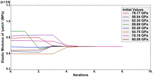
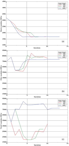
The updating of all three parameters was carried out from wide ranges of initial values. The estimated parameters were observed to be converging uniquely. A typical set of convergence curves are shown in with varying levels of random noise. It can be observed from the convergence curves that the global fibre modulus and the global matrix modulus were estimated uniquely, even in presence of a greater level of noise. The patch parameter started deviating slightly at 5% noise level and completely out of order at 10% noise. It can be well predicted that had the actual experimental data been acquired, the estimation of the patch modulus could only be done if the noise level was kept low.
Figure 11. Convergence curves for the elastic modulus of (a) matrix (b) fibre outside the ‘patch’ and (c) fibre within the ‘patch’.
Static characterization tests were carried out to determine the fibre elastic modulus and it was estimated to be 80.4 GPa. Later, the patch plate was cut to determine the average elastic parameters, i.e. the E1, E2, G12 and ν12 of the entire laminate by testing standard samples in Universal Testing Machine (Tinius Olsen Super L series). The results are presented in .
Table 5. Quasi-static characterization test results.
The accurate fibre volume ratios of the plate inside the patch area and outside the patch were determined to be 0.52 and 0.32, respectively by matrix burn off test in a muffle furnace. Considering the rule of mixture formula, the equivalent fibre modulus was estimated to be approximately 74.6 GPa. A separate model updating exercise was carried out considering the first 6 modes along with mode shapes as information and E1, E2, G12 and ν12 as parameters to be estimated, using eight noded shell element (S8R) in ABAQUS. The fibre modulus was estimated from the updated E1 value to be 81 GPa which is consistent with other observations. It is observed that inclusion of the effects of higher modes in FRFs was always more useful for convergence of the patch modulus as compared to the frequencies and mode-shape information, even at higher modes.
Conclusions
A finite element model updating programme implementing the inverse eigensensitivity algorithm is used to estimate the constituent level elastic parameters of FRP plates with local variations in the form of changes in elastic parameters within a patch area. The resultant variation in elastic modulus is realized as a change in fibre modulus within the patch, the location and extent of which is determined by observation of the mode shapes a priori. The algorithm uses the correlations between frequencies and mode shapes or FRFs computed using the finite element analysis and those obtained from experimental modal testing. A numerically simulated example explains the implementation procedure of the algorithm and also highlights the effects of random noise, location and extent of patch area on the accuracy of results obtained. A real experimental case study is conducted to test the efficiency of the algorithm to quantify the stiffness changes within a fabricated patch area with stiffness deficiency. The results indicate that the patch modulus can only be estimated correctly, if the mode-shape data are acquired with precision and the measurement noise is kept low. It has been observed that a local variation in properties cannot be treated in the same manner as most of the finite element model updating algorithm treats for global property variations. Frequency and mode-shape information may be less useful in this regard and use of localized information, such as FRF is mandatory. A judicious combination of these local-global response functions can resolve the practical issue of local as well as global variation in properties. In real life problems, where it is difficult to ascertain a-priori whether a patch is having really substantial contribution to global responses, the use of mode-shape information should be followed by the use of FRF information to observe any improvement in results. The method can be extended to track down the changes in constituent properties and their degradation from time to time, even if that happens locally at small regions, thus is suitable for condition assessment and health monitoring. The methodology is observed to work acceptably in the environment of modal and spatial sparsity. As the method includes eigenvector or FRF information, along with frequencies, only a few modes need to be measured to estimate a number of parameters simultaneously.
Acknowledgements
The authors duly acknowledge the contributions by KE Technical Textiles Pvt. Ltd., India in supplying the unidirectional FRP plates used in the experimental investigations.
Disclosure statement
No potential conflict of interest was reported by the authors.
References
- Daniel IM, Ishai O. Engineering mechanics of composite materials. 2nd ed. New York (NY): OUP; 2006.
- Ewins DJ. Modal testing: theory, practice and application. Heartfordshire: Research Studies Press; 2000.
- Lin RM. Development of a new and effective modal identification method – mathematical formulations and numerical simulations. J Vib Control. 2011;17(5):741–758. doi: 10.1177/1077546310376426
- Mottershead JE, Friswel MI. Model updating in structural dynamics: a survey. J Sound Vib. 1993;167(2):347–375. doi: 10.1006/jsvi.1993.1340
- Motthershead JE, Link M, Friswell MI. The sensitivity method in finite element model updating: a tutorial. Mech Syst Signal Process. 2011;25(7):2275–2296. doi: 10.1016/j.ymssp.2010.10.012
- Mohsen G-A, Ghasemi M. System identification method by using inverse solution of equations of motion in frequency domain. J Vib Control. 2013;19(11):1633–1645. doi: 10.1177/1077546312448079
- De Wilde WP, Narmon B, Sol H, et al. Determination of the material constants of an anisotropic lamina by free vibration analysis. Proceedings of the 2nd international modal analysis conference; Orlando, Florida; 1984. p. 44–49.
- Sol H. Identification of anisotropic plate rigidities using free vibration data [dissertation]. Belgium: Free University of Brussels; 1986.
- Deobald LR, Gibson RF. Determination of elastic constants of orthotropic plates by a modal analysis/Rayleigh-Ritz technique. J Sound Vib. 1988;124(2):269–283. doi: 10.1016/S0022-460X(88)80187-1
- Moussu F, Nivoit M. Determination of elastic constants of orthotropic plates by a modal analysis/method of superposition. J Sound Vib. 1993;165:149–163. doi: 10.1006/jsvi.1993.1248
- Grediac M, Paris PA. Direct identification of elastic constants of anisotropic plates by modal analysis: theoretical and numerical aspects. J Sound Vib. 1996;195(3):401–415. doi: 10.1006/jsvi.1996.0434
- Frederiksen PS. Experimental procedure and results for the identification of elastic constants of thick orthotropic plates. J Compos Mater. 1997;31:360–382. doi: 10.1177/002199839703100403
- Larsson D. Using modal analysis for estimation of anisotropic material constants. J Eng Mech. 1997;123(3):222–229. doi: 10.1061/(ASCE)0733-9399(1997)123:3(222)
- Mishra AK, Chakraborty S. Determination of material parameters of FRP plates with rotational flexibility at boundaries using experimental modal testing and model updating. Exp Mech. 2015;55(5):803–815. doi: 10.1007/s11340-014-9981-0
- Cugnoni J, Gműr T, Schorderet A. Inverse method based on modal analysis for characterizing the constitutive properties of thick composite plates. Comput Struct. 2007;85:1310–1320. doi: 10.1016/j.compstruc.2006.08.090
- Chen JC, Garba JA. Analytical model improvement using modal test results. AIAA J. 1980;25(11):1494–1499.
- Levin RI, Lieven NAJ. Dynamic finite element model updating using simulated annealing and genetic algorithms. Mech Syst Signal Process. 1998;12(1):91–120. doi: 10.1006/mssp.1996.0136
- Dascotte E. Material identification of composite structures from combined use of finite element analysis and experimental modal analysis. Proceedings of the 10th international modal analysis conference; 1992 Feb 3–7; San Diego, California; 1992. p. 1274–1280.
- Lin RM, Ewins DJ. Analytical model improvement using frequency response functions. Mech Syst Signal Process. 1994;8(4):437–458. doi: 10.1006/mssp.1994.1032
- Esfandiari A, Bakhtiari-Nejad F, Rahai A, et al. Structural model updating using frequency response function and quasi-linear sensitivity equation. J Sound Vib. 2009;326(3–5):557–573. doi: 10.1016/j.jsv.2009.07.001
- Esfandiari A, Bakhtiari-Nejad F, Sanayei M, et al. Structural finite element model updating using transfer function data. Comput Struct. 2010;88:54–64. doi: 10.1016/j.compstruc.2009.09.004
- Doebling SW, Farrar CR. Estimation of statistical distributions for modal parameters identified from averaged frequency response function data. J Vib Control. 2001;7(4):603–624. doi: 10.1177/107754630100700407
- Yesilyurt I, Gursoy H. Estimation of elastic and modal parameters in composites using vibration analysis. J Vib Control. 2015;21(3):509–524. doi: 10.1177/1077546313486275
- Chu YC, Rokhlin SI. Determination of macro- and micromechanical and interfacial elastic properties of composites from ultrasonic data. J Acoust Soc Am. 1992;92(2):920–931. doi: 10.1121/1.403962
- Mishra AK, Chakraborty S. Development of a finite element model updating technique for estimation of constituent level elastic parameters of FRP plates. Appl Math Comput. 2015;258:84–94.
- Mishra AK, Chakraborty S. Inverse detection of constituent level elastic parameters of FRP composite panels with elastic boundaries using finite element model updating. Ocean Eng. 2016;111:358–368. doi: 10.1016/j.oceaneng.2015.11.003
- Halpin JC, Tsai SW. Effects of environmental factors on composite materials. Daylon: Air Force Wright Aeronautical Labs; 1967. (Technical Report AfML-TR-67-423).
- Halpin JC, Kardos JL. The Halpin-Tsai equations: a review. Polymer Eng Sci. 1976;16(5):344–352. doi: 10.1002/pen.760160512
- Doebling SW, Farrar CR, Prime MB. A summary review of vibration-based damage detection methods. Shock Vib. 1998;30:91–105. doi: 10.1177/058310249803000201
- Pandey AK, Biswas M, Samman MM. Damage detection from changes in curvature mode shapes. J Sound Vib. 1991;145(2):321–332. doi: 10.1016/0022-460X(91)90595-B
- Qiao P, Lu K, Lestari W, et al. Curvature mode shape-based damage detection in composite laminated plates. Compos Struct. 2007;80(3):409–428. doi: 10.1016/j.compstruct.2006.05.026
- FEMtools v3.5.3. Dynamic Design Solutions NV; 2012.
- Abaqus v6.9. Dassault Systèmes Simulia Corp; 2009.
- Dascotte E, Strobbe J. Updating finite element models using FRF correlation functions. Proceedings of the 17th international modal analysis conference; 1999; p. 1169–1174.
- Lin RM, Lim MK, Wang Z. Structural damage detection using measured FRF data. Comput Methods Appl Mech Eng. 1997;147:187–197. doi: 10.1016/S0045-7825(97)00013-3
- Jung H. Structural dynamic model updating using eigensensitivity analysis [dissertation]. London, UK: Imperial College; 1992.
- Pulse LabShop, Ver. 13.1.0.246, Bruel & Kjær; 2008.
- ME’scope VES, Ver. 4.0.0.96, Vibrant Technology Inc.; 2007.