
 ?Mathematical formulae have been encoded as MathML and are displayed in this HTML version using MathJax in order to improve their display. Uncheck the box to turn MathJax off. This feature requires Javascript. Click on a formula to zoom.
Abstract
A method for the path synthesis of a planar five-bar mechanism based on wavelet analysis theory is proposed in this paper. Wavelet transform analysis is used to extract wavelet characteristic parameters(WCPs) from the basic dimensional types(BDTs) database. Combined the numerical atlas method with multidimensional search tree, a four dimensions search tree with a depth of five is obtained, in which numbers of leaf nodes are 4,096, and each node stores 59,787 groups of BDTs database numbers. Meanwhile, an index keyword database is established. By comparing the WCPs of a prescribed curve with index keywords, the leaf node where the desired mechanism is located is found. The WCPs of the BDTs in the leaf node are extracted, and a dynamic self-adaptive atlas database is established. Based on the design requirements, the desired mechanism can be obtained by fuzzy identification. Then, a mathematical model is established for calculating the actual sizes of the desired mechanism. The arbitrary design interval path synthesis of a five-bar mechanism is realized. Two examples are presented to demonstrate the veracity and practicality of the method proposed.
1. Introduction
As a classical problem, the dimensional synthesis of a linkage mechanism (including function synthesis, path synthesis and motion synthesis) has been a hot topic in the field of mechanism science. Many researchers have proposed numerous methods to solve dimensional synthesis problems [Citation1–10]. Compared with the precise point method, the analytical method and the approximate synthesis method, the numerical atlas method has the advantages of high synthesis precision and fast identification speed. Galan-Marin et al. [Citation11] used the global optimization algorithm for the closed path synthesis of multiple precise points. A new method was proposed in [Citation12], which could process DOF and the method combined topological optimization with dimensional synthesis of four-bar mechanism. Li et al. [Citation13] gave the periodic curve graph of the working area of seven-bar mechanism at each stage. However, due to the slow identification speed of the curve atlas database and the limited numbers of mechanism stored, the numerical atlas method effectively avoids the above drawbacks, which is widely used in various industries. Unruh et al. [Citation14] used the B-spline algorithm to establish a computer database of infinite points of the mechanism path. Marble and Mullineux [Citation15,Citation16] established numerical atlas databases of space four-bar mechanisms and spherical four-bar mechanisms. Based on the differential evolution algorithm, the solution to the synthesis problem of the spherical four-bar mechanism was completed by constructing the parametric equation in [Citation17]. Lee et al. [Citation18] used the performance sensitivity map to synthesize the linkage mechanism, and the synthesis of the three-position and four-position of the planar four-bar mechanism is realized. For the linkage path synthesis of a planar four-bar mechanism. Chanekar et al. [Citation19] performed multiple synthesis on a point path of a given linkage. First, they determined the vector modulus length of the crank and the point on the linkage, and next he used the least squares method. The mathematical algorithm determined the other driven edge parameters.
The transformation idea was utilized to transform the point on the linkage path into the linkage angle function. Yu et al. [Citation20] used the linkage angle function curve to synthesize the path curve based on the approximate synthesis method. For the rigid body guidance synthesis of a planar four-bar mechanism, Kim et al. [Citation21] completed the synthesis of the mechanism type and at the same time output the sizes of the mechanism. They proposed a unified rigid body guidance synthesis method by means of four rigid rectangular blocks. In the above studies, the periodic dimensional synthesis of linkage mechanisms is realized based on numerical atlas method.
Compared with the linkage curve of a planar four-bar mechanism, a planar five-bar mechanism has a richer curve shape, which is more widely used in industrial and medical fields. In recent years, there have been some related studies on the dimensional synthesis of a planar five-bar mechanism. Based on the two-phase synthesis method and a combined discrete Fourier descriptor, the path synthesis and optimization of a five-bar gear mechanism were carried out in [Citation22]. Al-Smadi et al. [Citation23] conducted the gear five-bar path synthesis by using nonlinear optimization method. Mundo et al. [Citation24] proposed to synthesize the path of a non-circular gear five-bar mechanism through inverse kinematics analysis. And the motion could be lowered by using the relationship between the two input angles. Next, the path synthesis of the linkage mechanism was completed by using genetic algorithm for optimization design. Through the curve envelopment theory, the connection mode of the five-bar slider crank was calculated, then, the path synthesis of the linkage mechanism was performed in [Citation25]. Using the continuous method, Starns et al. [Citation26] proposed a five-bar path synthesis method based on synthetic equation. Through a non-iterative algorithm, Balli et al. [Citation27] based on a variable topology and by means of a complex method to synthesize the planar five-bar linkage curve with the predetermined time scale. With the help of sequential transformations, Nokleby et al. [Citation28] used the finite difference method to optimize the sizes of the five-bar mechanism, then converted the sizes, and finally performed the periodic dimensional synthesis. However, most of the above researches on the planar five-bar path are integral period, and the arbitrary design interval path synthesis of the planar five-bar based on the numerical atlas method is rare. Due to the richness of the coupler curve shape of a planar five-bar mechanism, the application prospect is far-reaching. Therefore, based on the numerical atlas method, the open path synthesis of a planar five-bar mechanism becomes a focus.
Wavelet theory was first applied to the field of signal processing analysis. At present, the application of the wavelet principle to the linkage mechanism is relatively rare. The crank-rocker database was established by wavelet neural network theory, and combined with the reduction of design space method for linkage path synthesis in [Citation29]. Haar wavelets were used to extract the characteristic parameters of the planar four-bar linkage curve. Sun et al. [Citation30] extended the WCPs method to the non-periodic dimensional synthesis of spatial linkage mechanisms. The above methods can well solve the dimensional synthesis problem of the prescribed design interval, however, in the practical problem, the design interval is often unknown. Since the design interval is an independent variable, in the process of solving the dimensional synthesis problem without the prescribed design interval by using the above method, the prescribed design interval is required. And there is no guarantee that the global optimal solution exists in the prescribed design interval. Moreover, compared with the planar four-bar mechanism, the parameter dimensions of a planar five-bar mechanism increase, which makes the WCPs database huge. Aiming at these problems, a non-predetermined design interval path synthesis method based on a dynamic self-adaptive atlas database is proposed in this paper. The dynamic self-adaptive atlas database achieves dimensional synthesis of a planar five-bar mechanism. The method proposed in this paper has the characteristics that the database takes up less space, covers more types of mechanism, and has shorter matching time.
The paper is organized as follows: the mathematical model of a planar five-bar mechanism is established, and the coupler curve of the mechanism is analyzed and preprocessed in Section 2. The wavelet transform is applied to the five-bar linkage path in Section 3. The dynamic self-adaptive atlas database of the planar five-bar mechanism is established by using multi-dimensional search tree. According to the fuzzy identification method, multiple groups of desired basic dimensional types are output in Section 4. The theoretical equations for calculating the actual sizes of the basic dimensional types are proposed in Section 5. In Section 6, two examples are presented to verify the effectiveness and practicality of the proposed method.
2. Analyzing and preprocessing of a coupler curve
2.1. Analyzing of the coupler curve of a five-bar mechanism
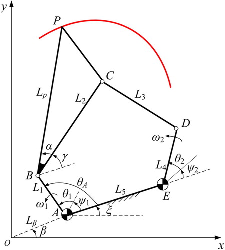
The planar five-bar mechanism model is shown in Figure . L1, L2, L3, L4 and L5 are the bars of the mechanism, wherein L1 and L4 are defined as two input bars. The point P is an arbitrary point on the linkage L2. Lp is the length of BP, and α is the angle between BP and linkage L2. ξ is the angle between the frame AE and the x-axis. ψ1 is the initial angle of the bar L1. θ1 is the input angle of L1. ψ2 is the initial angle of the bar L4. γ is the angle between the linkage L2 and the frame AE. The gear ratio of the mechanism is ω2: ω1, and the ratio is defined as R in this paper.θ2 is the input angle of the bar L4. θ1 and θ2 can be expressed as θ1(t) = ω1t and θ2(t) = ω2t. θA is the angle between the input bar L1 and the frame AE. It can be known from the geometric relationship that γ is a function about time t and the value of γ is determined by L1, L2, L3, L4, L5, ψ2, ψ1, θ1 and R. Lβ is the distance between the origin O of the coordinate and the point A, and β is the angle between the OA and the x-axis.
Figure 1. The planar five-bar mechanism model.
In Figure , the x-axis is defined as the real axis, and the y-axis is defined as the imaginary axis. Therefore, in the complex plane, the path curve of the point P is a function about time t, and its equation is as follows:
(1)
(1) where i is an imaginary unit, 0 < θ1(t) ≤ θs (θs is the maximum rotation angle of the input bar L1 relative to the initial angle ψ1. In this paper, θs is defined as the design interval.)
It can be seen from Equation (1) and the geometric relationship of γ that the coupler curve function of a five-bar mechanism includes L1, L2, L3, L4, L5, ψ2, R, Lβ, β, θs, Lp, α, ξ and ψ1. These parameters are defined as five-bar mechanism path parameters. If the 14-dimensional path parameters are all taken as the basic dimensional types of the mechanism, and its corresponding wavelet coefficients (the wavelet approximation and detail are collectively referred to as wavelet coefficients.) are directly stored together to establish an output characteristic parameter database, which will cause problems that it is too large data volume, basic dimensional type redundancy, long fuzzy recognition time, and low synthesis efficiency. Aiming at these problem, the preprocessing and wavelet transform method are used in this paper to eliminate the influence of the parameters (Lp and α) of the point P, the parameters (Lβ and β) of the frame AE, and the proportional scaling of the bar lengths. And the purpose of eliminating the repetitive BDT in the database is achieved without reducing the basic dimensional type of the mechanism.
2.2 Preprocessing of a coupler curve
In order to avoid establishing a huge numerical atlas database, the idea of preprocessing is adopted. The following preprocessing is performed on the coupler curve.
All sample points on the original curve are rotated counterclockwise by Δθ (Δθ = θs / 2j) around the origin O of the coordinate, where θs is the maximum rotation angle of the input bar L1 relative to the initial angle ψ1; j is the decomposition level (j ∈N+). The (n + 1)th sample point on the original curve substracts the nth sample point on the rotated curve, which can get the difference vector between two points. Then, each difference vector is connected end to end in sequence. The difference vectors and the curve after rotation can be used to reconstruct the original path curve.
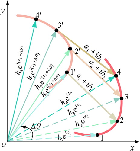
For example, the coupler curve of a given five-bar mechanism, four sample points can be obtained by discrete sampling (h1eiτ1, h2eiτ2, h3eiτ3 and h4eiτ4). Then, a group of vectors can be obtained by rotating counterclockwise the original curve by Δθ. And they can be expressed as h1ei(τ1+Δθ), h2ei(τ2+Δθ), h3ei(τ3+Δθ) and h4ei(τ4+Δθ). According to the above method, the difference vectors can be obtained and they can be expressed as a1 + ib1, a2 + ib2 and a3 + ib3. The schematic graph is shown in Figure . According to Euler formula and mathematical recursion relation, the original curve can be reconstructed by the difference vectors. The specific proof process is as in Appendix 1.
Figure 2. Schematic graph of preprocessing.
Based on the above analysis, the output function curve of a five-bar path is rotated counterclockwise by Δθ degree around the origin O. The specific preprocessing process is as follows:
(2)
(2) where m = 1, 2, … , 2j, j is the decomposition level (j ∈N+), θs is the design interval, tm is the moment when an arbitrary point P on the linkage L2 rotates to the mth sample point, z(tm) are the mth sample points of the coupler curve, and Z(tm) are the mth characteristic vectors of the coupler curve.
Based on the above conclusions, Equation (1) is substituted into Equation (2) yields:
(3)
(3) According to the geometric relationship, θ1(tm) = θ1(tm−1) + θs / 2j, the following equation can be obtained:
(4)
(4)
Let , and the characteristic vectors can be expressed as follows:
(5)
(5) After preprocessing the points on the path, the characteristic vectors Z(tm) are obtained, which contains the characteristics of the original curve. Therefore, the numerical atlas database can be reduced without affecting the fuzzy identification accuracy.
3. Wavelet analysis of a coupler curve
According to Equation (5), the path curve of an arbitrary five-bar mechanism can be represented by a set of curve characteristic vectors Z(t1), Z(t2), … , Z(t2j). Based on the wavelet decomposition theory [Citation31], the wavelet decomposition is performed on the curve characteristic vector of a five-bar mechanism; the detailed decomposition and application process of the wavelet theory are shown in Appendix 2. The wavelet transform is implemented by the following two functions:
(6)
(6)
(7)
(7) where hϕ is scaling function, hψ is wavelet function, l is the number of sample points (l = 1, 2, … , 2j), j is the decomposition level, t1 is the initial time, and ts = θs / ω1.
The j level decomposition equation of the five-bar linkage path is as follows:
(8)
(8) where
(9)
(9)
(10)
(10)
(11)
(11)
(12)
(12) where J = 1, 2, … , j, l = 1, 2, … , 2j-J, a(j, 1) is the first approximation vector of j-level wavelet decomposition, which is defined as the wavelet approximation in this paper, and b(J, 1) is the lth of J-level wavelet detail vector, which is referred to as wavelet detail.
Equation (5) is substituted into Equations (9) and (10) yields:
(13)
(13)
(14)
(14)
The wavelet details are normalized, that is, all the items of the wavelet detail are divided by the first item of the wavelet detail:
(15)
(15) where d(J, l) is defined as the wavelet characteristic parameter of the five-bar coupler path curve in this paper.
The length of each bar of the five-bar mechanism is scaled proportionally, the parameters (Lβ, β and ξ) of the frame AE and the parameters (Lp and α) of the point P are changed. The wavelet details of the coupler curve after the parameters changed can be obtained by Equation (14). The equation is described as follows:
(16)
(16) where b′′(J, l) is the wavelet detail after changing the deflection angle of the frame, the position of the point P and the length of the bars. L′′p, α′′ and ξ′′ are the changed parameters.
According to Equation (15), the normalized wavelet detail is as follows:
(17)
(17) where d′′(J, l) is the wavelet characteristic parameter after changing the deflection angle of the frame, the position of point P and the length of the bars.
It can be seen from Equations (15) and (17) that the normalized wavelet details are the same, which indicates that the wavelet characteristic parameters are not affected by the parameters (Lp and α) of the point P, translation and rotation of the frame, and bar length scaling. Therefore, L1, L2, L3, L4, L5 and ψ2 are the BDTs. In addition to the BDTs and ψ1, the other parameters of the five-bar mechanism path are changed which has no effects on the WCPs. An example is given to prove above conclusion in Appendix 3.
4. Path synthesis of a five-bar mechanism
4.1. Analysis of wavelet decomposition levels
According to the wavelet multi-resolution analysis theory, the target curve is gradually multi-dimension refined by the expansion and translation wavelet function. The wavelet coefficients are used to describe the similarity between the target curve, the scaling function and the wavelet function, which realizes characteristic information extraction. It is known from the wavelet theory that the wavelet approximation a(j, l) is applied to describe the general trend of the curve at the current scale, and the wavelet detail b(J, l) is used to describe the change of the curve at the current scale. The j is the decomposition levels of the wavelet transform. As j increases, the resolution is higher. When j approaches infinity, the Haar wavelet is closer to the original curve. For the open interval path synthesis of a planar five-bar mechanism, the six-level wavelet decomposition can be used to describe its output characteristics well. When the five-level wavelet decomposition is adopted, the number of sample points will be reduced from 64 to 32, which leads to inaccurate characteristics extraction of the original path. And the synthesis result will be affected. Therefore, six-level wavelet decomposition is adopted in this paper to achieve the path synthesis of a five-bar mechanism. An example is presented as follows:
The prescribed path curve is produced by a planar five-bar mechanism (L1 = 38, L2 = 119, L3 = 98, L4 = 20, L5 = 125). It can be seen from the analysis in section 2.2 that the characteristic vector Z(tm) is decomposed by the six-level wavelet theory in this paper. The function curve of the pre-processed sample points is shown in Figure (a). The function curve of wavelet approximations is shown in Figure (b). The function curve of six-level wavelet details is shown in Figure (c). The function curve of five-level wavelet details is shown in Figure (d), and so on, the function curve of one-level wavelet details is shown in Figure (h). Since the prescribed path curve of the five-bar mechanism is continuous and smooth (regardless of the cusp problem), the five-level WCPs are selected to facilitate the subsequent partitioning.
Figure 3. Function curves of the pre-processed sample points and wavelet coefficients.
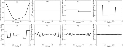
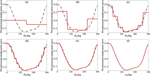
Figure (a) shows the reconstructed curve using wavelet approximations and six-level wavelet details (red solid line). The reconstructed curve using six-level wavelet coefficient and five-level wavelet details is shown in Figure (b), and so on, the reconstructed curve using all the wavelet coefficients is shown in Figure (f). From the above reconstructed curve, it can be seen that the reconstructed curve of the four-level, five-level and six-level summation can reconstruct the prescribed curve approximately. Therefore, the WCPs of four-level, five-level and six-level are extracted for fuzzy recognition. So that the calculation amount is greatly reduced and the calculation efficiency is improved without affecting the calculation accuracy.
Figure 4. Reconstructed curves.
4.2. Steps of the path synthesis
According to the relation of complex number operation, the wavelet transform of curve characteristic vector is equivalent to the wavelet transform of real part and imaginary part of curve characteristic vector. And the trend and characteristics of a couple curve at low resolution can be expressed by (j-1)-level WCP (d(j-1,1) and d(j-1,2)). Through the above analysis, a database containing 22,039,711,200 groups of BDT is established in this paper. The specific steps are as follows:
The basic dimensional types (BDTs) database includes L1′, L2′, L3′, L4′, L5′ and the initial angle ψ2′ of the bar L4′. The total lengths of the five bars are 400, the step size is 3, and the Grashof criterion is met [Citation32]. The initial angle ψ2′ is taken from 0° to 340° every 20°, and a BDTs database of 156,978 groups is established.
The range of the design interval is 31° to 300°, and the step size is 3°. The initial angle ψ1′ of the input bar L1′ is taken from 4° to 361° every 3°. The 13 gear ratios are 0.1, 0.2, 0.3, 0.5, 1.5, 2, −0.1, −0.2, −0.3, −0.5, −1, −1.5 and −2. For convenience of calculation, the following initial conditions are set in this paper: Lp′ = 1, α′ = 0, ξ′ = 0, β′ = 0 and Lβ′ = 0.
Discrete sampling is carried out for the non-periodic path generated by the BDTs. The sample points are preprocessed, the six-level wavelet decomposition is performed, and the two terms of the normalized wavelet details (d′(j-1,1) and d′(j-1,2)) are extracted.
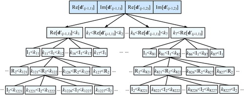
In order to shorten the time of fuzzy identification, a multi-dimensional search tree is used to partition the BDTs in the each design interval, and an index keywords database is established. First, the basic dimensional types are sorted according to the real part of the first item of the WCPs. A four dimensions search tree with a depth of two is established, in which the keywords (k1, k2, k3, k4, k5, k6 and k7) of the sub-tree node are the octant value of the sequence formed by the real part of the first item of the WCPs (as shown in Figure , where MST represents multidimensional search tree, Re(d′(j-1,1)) and Im(d′(j-1,1)) are respectively the real and imaginary parts of the first item of the WCPs. Re(d′(j-1,2)) and Im(d′(j-1,2))) are the real and imaginary parts of second item of the WCPs. I1 represents Im(d′(j-1,1)), R2 represents Re(d′(j-1,2)), and I2 represents Im(d′(j-1,2)). Then, the sub-tree is further divided according to the imaginary part of the first item of the WCPs, the real and the imaginary parts of the second item of the WCPs. Each leaf node contains the numbers of BDTs and gear ratio, occupying only 4 GB of memory. Finally, a four dimensions search tree with a depth of five is obtained, in which the numbers of leaf nodes are 4,096, and each node stores 59,787 groups of the numbers of BDTs and gear ratios. As shown in Figure , the keywords (k11, k12, … , k17) of the sub-tree node are the octant value of the sequence block formed by the imaginary part of the first item of the WCPs, the keywords (k121, k122, … , k777) of the sub-tree node are the octant value of the sequence block formed by the real part of the second item of the WCPs and the keywords (k1221, k1222, … , k7777) of the sub-tree node are the octant value of the sequence block formed by the imaginary part of the second item of the WCPs. The index keyword database contains index keyword sequences of 90 groups design intervals, and each sequence comprises 4,095 keywords. In this way, the WCPs database of step (3) can be deleted.
The 65 sample points are extracted from the prescribed curve; they are preprocessed and then decomposed by six-level wavelet to extract the normalized WCPs. The query data are Re(d (j-1,1)), Im(d (j-1,1)), Re(d (j-1,2)), Im(d (j-1,2)). The above four-dimensional query data are started from the root node. By comparing the above four-dimensional query data with the keywords in the index keyword database, the leaf node where the BDT of the desired mechanism is located can be obtained.
Based on the multi-dimension analysis theory, the j-1 and j-2 levels WCPs of the couple curve in the leaf node where the desired mechanism is located are extracted. Since each leaf node only stores about 59,787 groups of mechanism numbers, each number occupies 6 characters. After compression, each leaf node occupies about 300 KB of disk space. Then, a dynamic self-adaptive atlas database is established (as shown in Figure , DSAD means dynamic self-adaptive atlas database). The fuzzy identification is used to search the better BDTs. According to the degree of similarity of the WCPs in the self-adaptive atlas database and the WCPs of the prescribed curve, the BDT satisfying the design requirements is retrieved from the dynamic self-adaptive atlas database. The similarity function can be expressed as
(18)
The synthesis results obtained by multidimensional search tree will not necessarily be the most recent value of the query data. During the backtracking process, the whole tree will be searched again for the better data [Citation33]. There is no backtracking in this paper, and the genetic algorithm is used to search for approximate optimal results near the synthesis results. In the process of dimensional synthesis using the dynamic self-adaptive atlas database, only the BDTs database, the index keyword database and the leaf nodes are needed to realize the path synthesis problem of the arbitrary design interval of the five-bar mechanism. Compared with the traditional numerical atlas method, the fuzzy recognition efficiency is improved and the storage space is saved, which is convenient for storage and transmission.
Figure 5. Synthesis steps.
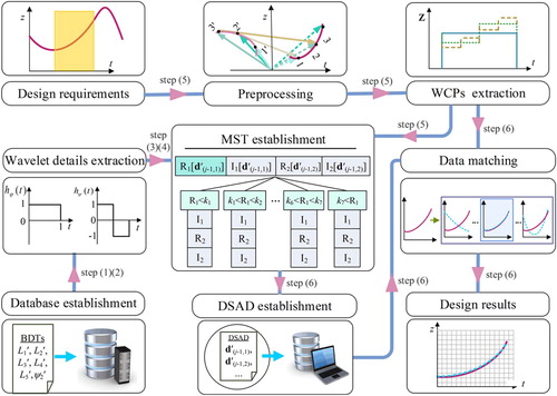
Figure 6. Multidimensional search tree.
5. Calculation of the actual sizes of the desired mechanism
According to the internal relationship of the wavelet coefficients of the desired mechanism and the wavelet coefficients of the BDT generating mechanism, the actual size and installation position of the desired mechanism are calculated. The specific theoretical equations are as follows:
Length Lp of BP:
When the mechanism is determined, the angle γ between the linkage L2 and the frame AE is also determined, so s(t) is determined. Therefore, the following equation can be obtained according to Equation (14):
(19)
(19) where b(j,1) is the first of j-level wavelet detail of the prescribed curve, and b′(j,1) is the first of j-level wavelet detail of the BDT generating mechanism.
The equation above is simplified as followings:
(20)
(20) According to the step (2) in Section 4, L′p = 1, α′ = 0 and ξ′ = 0 are substituted into Equation (20):
(21)
(21)
(22)
(22)
(23)
(23) (2) The parameters Lβ and β of the frame AE
According to Equation (13), the WCPs of the path of the BDTs output are described as follows:
(24)
(24) Substituting L′β = 0, β′ = 0, L′p = 1, α′ = 0 and ξ′ = 0 of the basic dimensional type into Equation (24):
(25)
(25)
Substituting Equation (25) into Equation (13):
(26)
(26) The values of Lβ and β can be obtained by the following two equations:
(27)
(27)
(28)
(28) where a(j, 1) is the first of j-level wavelet approximation of the prescribed curve, and a′(j,1) is the first of j-level wavelet approximation of the BDT generating mechanism.
| (3) | Actual lengths of the desired mechanism | ||||
The first sample point obtained by the Equation. (1) is described as follows:
(29)
(29) The length of each bar can be calculated by the following equations:
(30)
(30)
(31)
(31)
(32)
(32) where M = 1, 2, 3, 4, 5, L′M are the basic dimensional types.
| (4) | The value of ξ and α | ||||
The frame AE rotation angle ξ and the angle α between the bar BP and the linkage L2 can be obtained by the following two equations:
(33)
(33) Substituting Equation (33) into Equation (23):
(34)
(34)
According to Equations (22), (27), (28), (31), (32), (33) and (34), all the actual size of the desires mechanism can be calculated.
6. Examples
6.1. Example 1
To verify the correctness of the above theoretical method, the third example in the reference [Citation34] is used as the comparison example in this paper. The curve of the function as follows:
The planar four-bar mechanism is used to synthesize the above curve in the reference [Citation34], which similarity is 2.16 · 10−4. According to the wavelet transform analysis presented in this paper, the WCPs of the given function are extracted. Using the method proposed in this paper, the above function curve is synthesized by a five-bar mechanism. The optimized synthesis results of top three groups with the least similarity are shown in Table . The approximate optimal synthesis (that is the first group of synthesis results) comparison graph is shown in Figure , and the error graph is shown in Figure . Under the same condition of the similarity algorithm, the similarity of the approximate optimal synthesis results is 3.3090 · 10−7.
Figure 7. Path synthesis comparison graph.
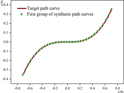
Figure 8. Path synthesis error graph.
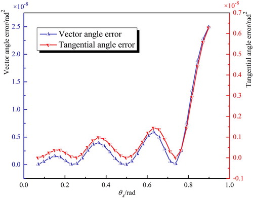
Table 1. Actual installation parameters.
The similarity algorithm in [Citation34] is described as follows:
αq (q = 1, 2, … , 64) is the angle between the preceding and following segments at point q. For convenience, this angle is defined as the vector angle in this paper.
βq is the angle between the tangential line of the required curve at point q and the following segment of the required polygon (the 65 points on the required curve are joined end to end to form a polygon). This angle is defined as a tangent angle in this paper.
Similarity
6.2. Example 2
The end-guided rehabilitation robot generally drives the patient’s hand or foot movement by a simple driving device, which guides the patient’s arm or leg to have a joint movement. During the training, the patient’s hand or foot is placed on the exercise device, and the exercise device guides the patient’s hand or foot to move. By controlling the movement path, the rehabilitation effect of moving the patient’s limbs can be achieved. Based on adopting the form of a planar five-bar mechanism, the first upper limb rehabilitation robot was developed successfully in the early 1990s [Citation35]. In this paper, a five-bar mechanism can be used as the driving part of the end-guided wearable rehabilitation robot. The method proposed in this paper is used to synthesize the ankle path of the leg-lifting process under natural gait proposed in reference [Citation36]. The specific synthesis process is as follows:
Discrete sampling is carried out on the prescribed path and then its wavelet details are extracted. The top 3 BDTs and similarities identified by a dynamic self-adaptive atlas database proposed in this paper are shown in Table .
The genetic algorithm (the maximum number of generations is limited to 200) is used to optimize the BDTs as shown in Table , and the WCPs of the first group of design results are shown in Table . The similarity of approximate optimal results is 2.2043 · 10−5. It takes 493.593 476 s for the establishment of a dynamic self-adaptive atlas database and fuzzy recognition.
The actual installation parameters of approximate optimal results are calculated, and the results are shown in Table . Approximate optimal results of the target mechanism graph are shown in Figure . The synthesis comparison graph is shown in Figure and error graph are shown in Figure .
Figure 9. First group of mechanism graph.
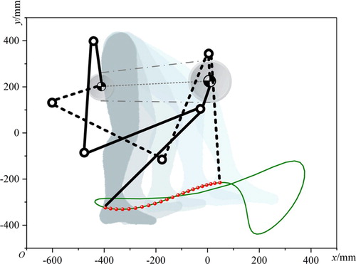
Figure 10. Comparison graph.
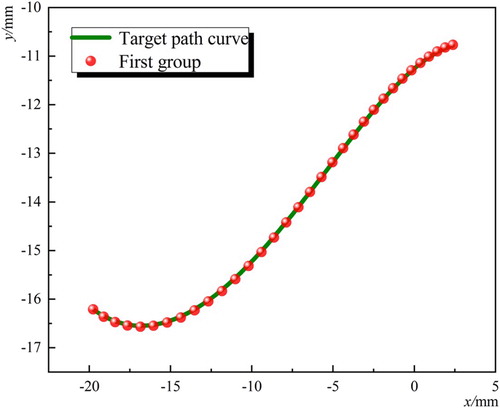
Figure 11. Error graph.
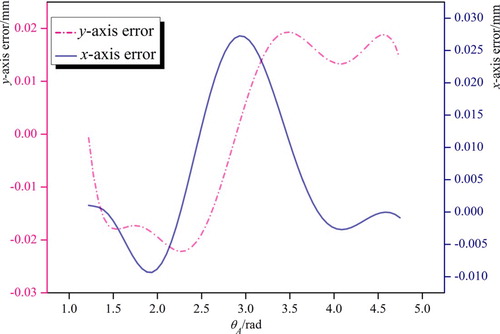
Table 2. Synthesis results.
Table 3. Optimized results.
Table 4. WCPs of the synthesis results.
Table 5. Actual installation parameters.
7. Conclusions
The mathematical model of a planar five-bar coupler path has been established. The coupler path has been studied; the characteristic of reconstructing the original curve by characteristic vectors and the rotated curve has been discovered, which achieves dimensionality reduction and avoid the numerical atlas database is huge. And the actual sizes of the planar five-bar mechanism have been calculated by theoretical equations. A BDTs database of 22,039,711,200 groups of the five-bar mechanisms including 13 gear ratios has been established to achieve cluster storage of the same BDT.
Using the multidimensional search tree, the WCPs of the BDTs in the 90 design intervals have been partitioned. A dynamic self-adaptive atlas database has been established, and non-periodic path synthesis has been realized. When traditional algebraic methods and geometric methods use point constraints to perform dimensional synthesis, there will be problems such as the number of point limitation, the difficulty of solving the equations, and the order and the branch. The WCPs method overcomes the above problems.
Compared with the linkage curve of a planar four-bar mechanism, a planar five-bar mechanism has a richer curve shape. The synthesis results of the five-bar mechanism are increased by 1,000 times compared with the four-bar mechanism in Example 1. The foot rehabilitation has been performed on the terminal rehabilitation patients by means of the WCPs method. The five-bar mechanism achieves the path of the leg-lifting process under natural gait and obtains approximate optimal results with a similarity of 2.2043 · 10−5. Thus, the method provides a more diverse rehabilitation path for rehabilitation patients.
Acknowledgment
All findings and results presented in this paper are those of the authors and do not represent those of the funding agencies.
Disclosure statement
No potential conflict of interest was reported by the author(s).
Additional information
Funding
References
- Russell K, Shen Q. Expanded spatial four-link motion and path generation with order and branch defect elimination. Inverse Probl Sci Eng. 2013;21(1):129–140.
- Zhao P, Li X, Purwar A, et al. A task-driven unified synthesis of planar four-bar and six-bar linkages with R-and P-joints for five-position realization. J Mech Rob. 2016;8(6):061003.
- Kim JW, Jeong SM, Kim J, et al. Numerical hybrid Taguchi-random coordinate search algorithm for path synthesis. Mech Mach Theory. 2016;102:203–216.
- Cabrera JA, Simon A, Prado M. Optimal synthesis of mechanisms with genetic algorithms. Mech Mach Theory. 2002;37(10):1165–1177.
- Lin WY. A GA–DE hybrid evolutionary algorithm for path synthesis of four-bar linkage. Mech Mach Theory. 2010;45(8):1096–1107.
- Alt H. Das konstruieren von Gelenkvierecken unter Benutzung einer Kurventafel. Z. VDI. 1941;85:69–72.
- Zhang C, Norton PERL, Hammonds T. Optimization of parameters for specified path generation using an atlas of coupler curves of geared five-bar linkages. Mech Mach Theory. 1984;19(6):459–466.
- Matekar SB, Gogate GR. Optimum synthesis of path generating four-bar mechanisms using differential evolution and a modified error function. Mech Mach Theory. 2012;52:158–179.
- Liu Y, Xiao R. Optimal synthesis of mechanisms for path generation using refined numerical representation based model and AIS based searching method. J Mech Des. 2005;127(4):688–691.
- Chu JK, Sun JW. Numerical atlas method for path generation of spherical four-bar mechanism. Mech Mach Theory. 2010;45(6):867–879.
- Galan-Marin G, Alonso-Sanchez FJ, Del Castillo-Granados JM. A methodology to learn designing optimal mechanisms for path generation. Comput. Appl. Eng. Educ. 2010;18(1):87–92.
- Kim SI, Kim YY. Topology optimization of planar linkage mechanisms. Int. J. Numer. Methods Eng. 2014;98(4):265–286.
- Li RQ, Dai JS. Workspace atlas and stroke analysis of seven-bar mechanisms with the translation-output. Mech Mach Theory. 2012;47:117–134.
- Unruh V, Krishnaswami P. A computer-aided design technique for semi-automated infinite point coupler curve synthesis of four-bar linkages. J Mech Des. 1995;117(1):143–149.
- Marble SD, Pennock GR. Algebraic-geometric properties of the coupler curves of the RCCC spatial four-bar mechanism. Mech Mach Theory. 2000;35(5):675–693.
- Mullineux G. Atlas of spherical four-bar mechanisms. Mech Mach Theory. 2011;46(11):1811–1823.
- Penunuri F, Peón-Escalante R, Villanueva C, et al. Synthesis of spherical 4R mechanism for path generation using differential evolution. Mech Mach Theory. 2012;57:62–70.
- Lee MY, Erdman AG, Faik S. A generalized performance sensitivity synthesis methodology for four-bar mechanisms. Mech Mach Theory. 1999;34(7):1127–1139.
- Chanekar PV, Ghosal A. Optimal synthesis of adjustable planar four-bar crank-rocker type mechanisms for approximate multi-path generation. Mech Mach Theory. 2013;69:263–277.
- Yu HY, Tang DW, Wang ZX. Study on a new computer path synthesis method of a four-bar linkage. Mech Mach Theory. 2007;42(4):383–392.
- Kim BS, Yoo HH. Body guidance syntheses of four-bar linkage systems employing a spring-connected block model. Mech Mach Theory. 2015;85:147–160.
- Lin WY. Optimum synthesis of planar mechanisms for path generation based on a combined discrete Fourier descriptor. J Mech Rob. 2015;7(4):041023-1–041023-11.
- Al-Smadi YM, Russell K, Sodhi RS. Geared five-bar path generation with structural constraints. Inverse Probl Sci Eng. 2009;17(8):1059–1072.
- Mundo D, Gatti G, Dooner DB. Optimized five-bar linkages with non-circular gears for exact path generation. Mech Mach Theory. 2009;44(4):751–760.
- Zhou H, Ting KL. Path generation with singularity avoidance for five-bar slider-crank parallel manipulators. Mech Mach Theory. 2005;40(3):371–384.
- Starns G, Flugrad DR. Five-bar path generation synthesis by continuation methods. J Mech Des. 1993;115(4):988–994.
- Balli SS, Chand S. Five-bar motion and path generators with variable topology for motion between extreme positions. Mech Mach Theory. 2002;37(11):1435–1445.
- Nokleby SB, Podhorodeski RP. Optimization-based synthesis of Grashof geared five-bar mechanisms. J Mech Des. 2001;123(4):529–534.
- Galán-Marín G, Alonso FJ, Del Castillo JM. Shape optimization for path synthesis of crank-rocker mechanisms using a wavelet-based neural network. Mech Mach Theory. 2009;44(6):1132–1143.
- Sun JW, Liu WR, Chu JK. Synthesis of a non-integer periodic function generator of a four-bar mechanism using a Haar wavelet. Inverse Probl Sci Eng. 2016;24(5):763–784.
- Sun JW, Liu WR, Chu JK. Dimensional synthesis of open path generator of four-bar mechanisms using the haar wavelet. J Mech Des. 2015;137(8):082303.
- Ting KL. Five-bar Grashof criteria. J Mech Des N Y. 1986;108(4):533–537.
- Silpa-Anan C, Hartley R. Optimised KD-trees for fast image descriptor matching. Natl Conf Comput Vis Pattern Recognit Image Process Graph. IEEE. 2008:1–8.
- Marin FTS, Gonzalez AP. Open-path synthesis of linkages through geometrical adaptation. Mech Mach Theory. 2004;39(9):943–955.
- Krebs HI, Ferraro M, Buerger SP, et al. Rehabilitation robotics: pilot trial of a spatial extension for MIT-Manus. J. NeuroEng. Rehabil. 2004;1(1):5.
- Alamdari A, Haghighi R, Krovi V. Stiffness Modulation in an Elastic Articulated-Cable Leg-Orthosis Emulator: theory and Experiment. IEEE Trans. Robot. 2018;99:1–14.
Appendices
Appendix 1:
As shown in Figure , the difference vectors a1 + ib1, a2 + ib2 and a3 + ib3 and the sample points h1ei(τ1+Δθ), h2ei(τ2+Δθ), h3ei(τ3+Δθ) and h4ei(τ4+Δθ) are known. The sample points of the original curve (h1eiτ1, h2eiτ2, h3eiτ3 and h4eiτ4) are reconstructed by the difference vectors and the sample points of the rotated curve. The specific certification process is described as follows:
(A1)
(A1)
(A2)
(A2)
(A3)
(A3)
Using the Euler equation, Equation (A1) can be expanded as
(A4)
(A4) By the equal correspondence between the real part and the imaginary part, the following equations can be obtained:
(A5)
(A5)
(A6)
(A6) The h2 value can be obtained by the following equation:
(A7)
(A7) Substituting Equation (A7) into Equation (A6) yields:
(A8)
(A8) Substitute the value of τ2 into Equation (A7) to solve the h2 value. By analogy, the value of hneiτn can be restored (where n = 2, 3, 4). The difference vector can restore the original curve, which demonstrates the feasibility of the preprocessing method.
Appendix 2:
Based on the wavelet decomposition theory, the wavelet decomposition is performed on the curve characteristic vector of a five-bar mechanism, and the first-order wavelet decomposition of the curve feature vector can be expressed as
(A9)
(A9)
(A10)
(A10)
(A11)
(A11) where l is the number of sample point (l = 1,2, … , 2j), j is the decomposition level (j∈N+), t1 is the initial time, ts is sampling interval (ts = θs / ω1), hϕ is a scaling function, and hψ is a wavelet function, which can be expressed as
(A12)
(A12)
(A13)
(A13) According to wavelet multi-resolution analysis theory and recursive relationship, the wavelet transform equations as follows:
(A14)
(A14)
(A15)
(A15)
(A16)
(A16) where J = 2, 3, … , j, l = 1, 2, … , 2j-J. The second-level wavelet decomposition of curve characteristic vector is obtained by further decomposition of Equation (A15):
Three-level wavelet decomposition of curve feature vector:
j-level wavelet decomposition of curve feature vector:
(A17)
(A17) According to Equations (A16), (A17), and (A18), the j-level wavelet decomposition of the curve characteristic vector can be expressed as
(A18)
(A18) where
(A19)
(A19)
(A20)
(A20)
(A21)
(A21)
(A22)
(A22) J = 1, 2, … , j, l = 1, 2, … , 2j-J. a(j, l) is the first approximation vector of j-level wavelet decomposition, which is defined as the wavelet approximation in this paper. b(J, l) is the lth of J level wavelet detail vector, which is referred to as wavelet detail.
Table A1. WCPs of path curve of the five-bar mechanism.
Appendix 3:
L1, L2, L3, L4, L5 and ψ2 are the basic dimensional types. In addition to the BDTs and ψ1, the other parameters of the five-bar mechanism path are changed which has no effect on the WCPs. For example, the path parameters of the three groups of the given five-bar mechanism are as follows (where they have the same gear ratio: R = −0.2):
The first group of five-bar mechanism parameters are:
The second group of five-bar mechanism parameters are:
The third group of five-bar mechanism path parameters are:
The basic dimensional type (BDT) of the first group is the same as that of the second group, and Lβ, β, ξ, LP and α are different. The Lβ, β, ξ, LP and α of the second group are the same as those of the third group, and the initial angle ψ1 is different. The wavelet decomposition method is used to extract the WCPs of the coupler curves of three groups of five-bar mechanisms. The WCPs of the last 3 levels (d(4,1), d(4,2), d(4,3), d(4,4), d(5,1), d(5,2) and d(6,1)) of the three groups of mechanisms are listed in Table .
According to Table A.1, the five-bar mechanism with the same basic dimensional type has the same wavelet characteristic parameters (WCPs). Based on this discovery, the five-bar coupler curve with the same BDTs can be represented by the same group of WCPs.