
 ?Mathematical formulae have been encoded as MathML and are displayed in this HTML version using MathJax in order to improve their display. Uncheck the box to turn MathJax off. This feature requires Javascript. Click on a formula to zoom.
ABSTRACT
Background
Pain is characterized as a major symptom induced by tissue damage occurring from surgical procedures, whose potency is being experienced subjectively, while current pain relief strategies are not always efficient in providing individualized treatment. 3D printed implantable devices hold the potential to offer a precise and customized medicinal approach, targeting both tissue engineering and drug delivery.
Research design and methods
Polycaprolactone (PCL) and PCL – chitosan (CS) composite scaffolds loaded with procaine (PRC) were fabricated by bioprinting. Geometrical features including dimensions, pattern, and infill of the scaffolds were mathematically optimized and digitally determined, aiming at developing structurally uniform 3D printed models. Printability studies based on thermal imaging of the bioprinting system were performed, and physicochemical, surface, and mechanical attributes of the extruded scaffolds were evaluated. The release rate of PRC was examined at different time intervals up to 1 week.
Results
Physicochemical stability and mechanical integrity of the scaffolds were studied, while in vitro drug release studies revealed that CS contributes to the sustained release dynamic of PRC.
Conclusions
The printing extrusion process was capable of developing implantable devices for a local and sustained delivery of PRC as a 7-day adjuvant regimen in post-operative pain management.
1. Introduction
Physical damage of tissues provoked by surgical invasions has urged the concern to develop suitable dosage forms and regimen schemes for post-operative pain management and wound restoration. Over the years conventional treatment strategies based on per os or intravenous opioid medications have prevailed, contributing to the opioid pandemic, which has led to considerable problems such as opioid abuse, misuse, and diversion [Citation1]. Novel treatment patterns include the use of non-opioid analgesic combinations, such as nonsteroidal anti-inflammatory drugs (NSAIDs), N-methyl-D-aspartate (NMDA) receptor antagonists, acetaminophen, sodium channel blockers, and local anaesthetics, aiming on employing a multimodal method that synergistically combines low-concentration and shorter-duration pharmaceutical approaches [Citation2,Citation3].
The route of administration is a critical parameter, which affects the efficacy of an analgesic regimen as well as the patient’s compliance [Citation2]. Conventional treatments concerning oral and intravenous administration routes do not always succeed in delivering the drug sufficiently, leading to increased side effects and prolonged recovery times. In particular, permeability and solubility issues, along with first-pass metabolism and gastrointestinal degradation of the drug are notable obstacles associated with conventional dosage forms, which constantly hinder their bioavailability. On the other hand, extended-release implantable drug delivery devices can surpass these difficulties, targeting toward the elimination of high dosage drug intake and prolongation of therapeutic levels [Citation4]. Moreover, dosing schemes of oral and intravenous formulations, for chronic pain, are arduous and challenging; thus, patients do not often conform easily to medicinal treatments. Contrarily, implants, as targeted drug delivery systems (DDSs), aim on precisely and directly administer incorporated active substances, leading to improved quality of life and extended lifespans. Nevertheless, implantable devices conceal various limitations including post-surgical infections, compatibility issues, allergic reactions, and the need for replacement or revision surgeries. Therefore, it is crucial to thoroughly investigate these limitations to effectively mitigate associated risks [Citation5].
An implantable device can be a multifunctional pharmaceutical system inserted locally as a DDS, permitting the release of an Active Pharmaceutical Ingredient (API) [Citation6], and/or as a tissue support, enhancing the stiffness, regrowing, and replacing the tissue [Citation7,Citation8]. Implantable drug delivery devices are classified into active and passive systems according to their mechanism of releasing the drug; in active implants the release is dependent on spatiotemporal stimuli (e.g. temperature, pH, ultrasounds, etc.), whilst passive implants rely on passive drug diffusion and/or erosion as the main mechanisms for API release [Citation9]. In addition, mechanical, structural, and biological attributes define the critical quality prospects of a developed implantable device. Therefore, the stiffness of a certain 3D geometrical pattern, along with surface characteristics (e.g. hydrophobicity, crystallinity, roughness), impacts on both the physicochemical stability and the biological potential of tissue-implant interactions [Citation10]; consequently, affecting the efficacy and safety aspects of the pharmaceutical system [Citation11].
Materials commonly used for biodegradable passive implants are composed of synthetic [Citation12,Citation13] and/or natural polymers [Citation14,Citation15], aligning with the previously mentioned critical attributes. Polycaprolactone (PCL) is a synthetic and semi-crystalline biopolymer [Citation16], characterized by a slow hydrolytic degradation rate and notable biocompatibility, with minimal enzymatic involvement [Citation17]. Furthermore, PCL is compatible with a variety of both synthetic (e.g. polylactic co-glycolic acid (PLGA), polyurethane (PU), polyethylene glycol (PEG)) [Citation18,Citation19] and natural polymers (e.g. chitosan (CS), hyaluronic acid) [Citation20], as well as can be blended with minerals (e.g. Ca2+, Mg2+) [Citation21] and drugs [Citation22], forming composite compounds [Citation23]. On the other hand, CS is a natural semi-crystalline copolymer derived from the deacetylation of chitin, which defines its solubility, viscosity, and capability of chemical modification. Specifically, -NH2 groups amplify CS’s multifunctional biological efficacy [Citation24], such as its analgesic, antimicrobial [Citation25], antioxidant and hemostatic ability and responsiveness to stimuli [Citation24,Citation26]. Both polymers also exhibit thermoplastic properties; hence, precise investigation of their melting process is crucial in order to control their viscosity and crystallinity, ensuring efficient compatibility [Citation27]. Consequently, PCL/CS matrices prospect to create smart and dynamic implantable systems capable of vanishing while supporting tissue proliferation.
Within the framework of this study, procaine (PRC) was used as a model drug, to evaluate the manufacturability and release kinetics from biopolymeric 3D printed scaffolds composed of PCL, and PCL/CS. As a sodium channel blocker, PRC has a brief half-life time (t1/2 ≈15–20 min), resulting in short-term local anesthesia defined by limited toxicity [Citation28,Citation29]. The main objective was to formulate systems that provide an initial burst release to control acute pain (~48 h), targeting toward its release extension (until 1 week) from the biopolymeric formulation, hence, acquiring a longer drug dosing interval. In addition, PRC possesses anti-oxidative, anti-inflammatory, and anti-rheumatic properties that support the immune system [Citation30]. Studies have revealed that local anaesthetics are involved in tumor metastasis procedures, due to their epigenetic effects and cancer cell growth-inhibition [Citation31,Citation32]. Therefore, PRC-loaded implantable devices are assumed to be a potent adjunct in multimodal pain relief treatment, characterized by low toxicity levels after surgical operations.
3D printing (3DP) is an upcoming technology, within the pharmaceutical engineering field, introducing a layer-by-layer approach to fabricate quality-based and precise DDSs [Citation33,Citation34], and tissue engineering applications [Citation35,Citation36]. The noticeable aspect of this technology emerges from its potential on using a broad variety of different materials (e.g. polymers, drugs) by simultaneously combining the digital (e.g. g-code, machine learning) and mechanical engineering technology (e.g. multi-printing, printing inspection systems) [Citation37]. Hence, it is a promising technique with a prospect of developing novel and versatile tailor-made medicinal formulations, alternative to conventional treatments, characterized by tissue-simulated mechanical capabilities, precise structural and geometrical features, and adjustable drug concentrations (efficient also to low drug dosages), and release profiles [Citation38]. Moreover, it acquires the capability of using less amounts and/or re-use of biodegradable materials for the development and fabrication of personalized pharmaceutical applications, thereby contributing to cost reduction, shorter manufacturing times, and reduced CO2 emissions. Therefore, 3DP is described as a sustainable technique, fitting into a circular economy system [Citation39].
The aim of this study was to design and develop PRC-loaded 3D printed biopolymeric implantable scaffolds of PCL and CS composites, subsequently investigate and evaluate the release profile of the drug. Critical Process Parameters (CPPs) were defined during the development of 3D printed scaffolds by performing pre-formulation studies based on the investigation of the physicochemical properties of materials and their mixtures, mathematically predicting and assessing a Computer Aided Design (CAD) pattern and performing a real-time thermal imaging inspection during 3DP, pursuing the optimization of Critical Quality Attributes (CQAs) of the developed DDSs; thus, reflecting the establishment of a reliable 3DP process. This process aimed to achieve accurate geometrical pattern fidelity, a finite level/degree of stiffness for the scaffolds capable of supporting tissue mechanical stresses, and to meet the target of a prolonged in vitro release rate of PRC.
2. Materials and methods
2.1. Materials
Powdered PCL (MW: 50 kDa, particle size <600 μm) was purchased from Polysciences Inc, powdered CS (low MW, deacetylation degree ≥75%), PRC·HCl (MW: 272.22, ≥97% purity), acetic acid, ammonium acetate, methanol, N-Methyl-2-pyrrolidone (NMP) and phosphate buffered saline (PBS) tablets were supplied by Sigma Aldrich.
2.2. Methods
2.2.1. 3DP of empty and loaded scaffolds
In this study, five different PCL formulations were developed (). The PRC concentration was added at a 1% wt. level according to the prototype commercial product of procaine [Citation40]. The amount of CS was determined as 3% wt., as a multifunctional excipient [Citation41] in order to increase of the aqueous solubility of the scaffold and to promote the dissolution rate enhancement of PRC HCL.
Table 1. Formulations concerning raw materials and physical mixtures.
Printability studies, mechanical analysis, and in vitro drug release evaluation were carried out for different combinations and %wt. proportions of empty and PRC-loaded PCL scaffolds, except for formulation No.5, which consisted of a physical mixture of CS/PRC. Physicochemical analysis (FTIR, TGA, DSC) for all formulations, concerning raw materials (PCL, CS, PRC), physical mixtures (PMs) (PM2, PM3, PM4, PM5) and scaffold samples (SSs) (SS1, SS2, SS3, SS4) were performed.
2.2.1.1. CAD design preparation and optimisation
A general mathematical approach, concerning the digital design of the 3D model, was developed. This computational formula is an arithmetic progression describing a cuboid-like rectilinear pattern, in which length, width and height coordinates are expressed by variables (Figure S1-supplemetary material). This step aims on acquiring data of the % infill and dimensions of the pattern initially to the CAD structure. In particular, design characteristics, defining the 3D model (e.g. raster width, angles and gaps between the rasters), can be adjusted in order to avoid possible 3DP structural stability issues (e.g. positive or negative air gaps between the rasters) and predict the accuracy and integrity of the design [Citation42].
In this study, CAD model dimensions were thoroughly examined after defining the physicochemical properties of materials (e.g. thermal properties, MW), and evaluating the 3DP technological application (e.g. capabilities of 3D printer, nozzle diameter).
where,
a: raster width
b: scaffold width
c: scaffold length
x: percentage of infill
y: raster gap
n: a and y repetitions
Limitations:
0 < y < b − 2a
a < b/2
(n + 1)a + ny > 0
n ≥ 1, n ∈ N
a, b, c ∈ Z > 0
x ∈ [0,100]
*N: natural numbers, Z: integers
Dimensions of scaffolds were determined by EquationEquation (2)(2)
(2) . A square pattern was designed, where:
dnozzle = y = a
b = (2n + 1)a
Vstrand = π * a2 * b
Αsq = b2
infill(x%) = (2n + 1)a * b
raster gaps = Αsq – infill(x%)
where, d: diameter, V: volume, Α: area
Infill of the pattern was calculated by EquationEquation (2)(2)
(2) and Equation (3), where:
a = y = 0.84 mm
b = c = 10.92 mm
n = 6
x = 53.85%
2.2.1.2. Design and development of 3D printed scaffolds
The main scaffold design is described by a two-layer rectilinear pattern with a vertical raster orientation (0°/90°) and an even raster-gap existence (Figure S2-supplementary material). 3D CAD designs were created with Tinkercad (Autodesk Inc., U.S.A.) according to EquationEquation (2)(2)
(2) , for acquiring 3D structures based on pattern fidelity, infill integrity, and mechanical stability, and were exported as a Stereolithography (SLA) file (.stl) for 3DP use.
Scaffolds were fabricated with various compositions () with a 3D Bio-X bioprinter (Cellink, Sweden). Composite mixtures were initially weighed, transferred into a falcon tube, and vortexed for 5 min, in order to ensure proper particle dispersion. Subsequently, PCL or composite mixtures were loaded into a 10 mL stainless steel cartridge paired with an 18 G (0.84 mm) nozzle and placed into a thermoplastic printhead. All printing parameters (PP) () were adjusted by the Cellink Bio-X software. The determination of the suitable/appropriate printing temperature was made with FLIR One™ Pro Gen 3 thermal camera, smartphone accessory. The IR-camera was placed at 15 cm distance from the printing head in order to assure image focus and temperature measurement precision. Thermal videos were collected and analyzed in Vernier Thermal Analysis Plus app (Vernier Software & Technology, U.S.A.). IR temperature measurement accuracy was validated by an external thermometer (±1°C) [Citation43].
Table 2. Printability parameters concerning different adjustments on temperature ranges, pressure, and speed during 3DP of scaffolds. Shape fidelity (%) compared to actual size dimensions is noted.
The characterization of the printed scaffolds, as outlined in sections §2.2.2, §2.2.3, §2.2.4, §2.2.5, §2.2.6, was conducted for the PP1.
2.2.2. Thermogravimetric analysis and differential scanning calorimetry
Thermogravimetric analysis (TGA) and differential scanning calorimetry (DSC) were performed on raw materials, PMs, and extruded SSs in order to assess their thermal behavior.
TGA measurements were performed for samples (n = 3, 5–10 mg) in an open aluminum pan – to determine the absolute material degradation –, using a Q500 TGA (TA Instruments, New Castle, DE, U.S.A.), heating from room temperature to 500°C, applying a heating rate of 20°C/min and a nitrogen flow rate of 40 mL/min.
Standard (STDSC) and modulated DSC (MTDSC) thermal analyses were conducted with a DSC 214 Polyma (NETZSCH, Germany) and NETZSCH Proteus® thermal analysis software ver. 8.0 (NETZSCH, Germany) was used for the evaluation of thermal characteristics of materials. All samples (n = 3, 5–10 mg) were weighed in an aluminum pan, subsequently, crimped hermetically with a lid. Nitrogen flow rate was adjusted to 40 mL/min.
A heat-cool-heat cycle, with a 2 min interval isothermal process, prior to each heating cycle, was set for STDSC studies, analyzed from −10°C to 200°C or 250°C, at a heating rate of 20 °C/min and a cooling rate of 5°C/min. The cooling rate of thermal cycles was measured through an IR-camera, by performing a thermographic analysis of samples during their procedure of cooling after direct extrusion from the printer (Table S1-supplementary material).
The glass transition temperature (Tg) and the heat capacity change (ΔCp) of each extruded sample were evaluated through MTDSC studies, by analyzing the reversing signal. Sensitivity, heat flow, and time constant, and thermal resistances (TAU-R) calibrations were initially set, with indium as standard. The heating rate was adjusted at 1°C/min and a 0.8 °C/min modulated oscillation was applied. All samples were initially equilibrated for 5 min and examined in a temperature range between −75°C to 200°C.
Gordon-Taylor EquationEquation (4)(4)
(4) upon Simha-Boyer rule (Equationequation 5
(5)
(5) ) was implemented for the assessment of theoretical Tg values of SS2 and SS4; subsequently, compared with their experimental Tg. The calculated Tg values were defined and revealed the practical miscibility of the drug within the polymeric excipients [Citation43,Citation44].
where, Tg1 and w1 correspond to Tg and weight fraction of plain polymeric matrixes (e.g. SS1 and SS3), respectively, Tg2 and w2 indicate the Tg and the weight fraction of PRC, respectively, while Tg3 is the theoretical Tg of the polymeric-drug formulation (e.g. SS2 and SS4). K is a constant parameter and ΔCp1 and ΔCp2 are the heat capacity change during the glass transition of the polymeric formulation (e.g. SS1 and SS3) and PRC, respectively.
2.2.3. Fourier transform infrared spectroscopy
Compatibility of polymers along with API, concerning physicochemical interactions and compound-inspection analysis were assessed by FTIR analysis. Raw material, PMs, and SSs were examined with a Nicolet iS50FTIR Spectrometer (ThermoFisher Scientific Inc.) using attenuated total reflectance (ATR), in a spectra range of 4000 cmˉ1 and 700 cm¯1. Samples were run in triplicate with a resolution of 4 cm¯1 with 32 scans.
2.2.4. Morphological and elemental analysis of scaffolds
The examination of scaffolds’ dimensions, regarding the raster width and gap of the rectilinear pattern, was performed with a Leica Microsystems EZ4W microscope. Scaffold shape fidelity (SF) was evaluated, through a comparison between the actual 3D printed scaffold and the theoretical CAD pattern dimensions. Moreover, surface and microstructural properties concerning surface roughness and topology, internal pore formation, and interconnectivity were assessed with a dual beam focused ion beam scanning electron microscope (SEM; TESCAN Lyra3, Czech Republic) coupled with an energy-dispersive X-ray (EDS) detector. The examined scaffolds were initially entirely coated with a paper-thin layer of gold and detected under 20 kV accelerating voltage and 500 × magnification. The evaluation of the chemical analysis and elemental distribution data was performed by AztecLive software (OXFORD Instruments) [Citation45].
2.2.5. Tensile strength test evaluation
Mechanical strength analysis of 3D printed scaffolds was performed with a TA.Xtplus texture analyzer (Stable Micro Systems, Surrey, UK). 3D rectangular extruded SSs (length = 32.76 mm, width = 1.68 mm, n = 5) were tested in a vertical direction, until breakage. In particular, the samples were placed between two clamps at a 20 mm distance, and a cross head speed of 5 mm/s and a force of 300 N in the load cell was applied. Data were converted from force vs. displacement into stress vs. strain, and Young’s Modulus (E); Ultimate Tensile Strength (UTS), and Maximum Elongation (ME) were determined by the slope of the latter curve [Citation22].
2.2.6. In vitro drug release and drug content studies
Drug release and drug content studies were performed in vitro, in order to evaluate the released as well as the incorporated concentration of PRC from/into the polymeric matrices (scaffold = 100 mg, n = 4), respectively.
Drug release studies were performed in PBS dissolution medium (0.01 M, pH 7.4) under sink conditions at 37.0 ± 0.5°C. All scaffold formulations were immersed into vials containing 4 mL of medium and supernatant samples were withdrawn at specific time points (2 h, 6 h, 24 h, 48 h, and 1 week), followed by the replenishment of the withdrawn medium volume. The samples were analyzed in a High-performance liquid chromatography (HPLC; Agilent Technologies 1220 Infinity LC system, Agilent, U.S.A.) with a One™ 120 column 4.6 × 250 mm, 5 μm, RP C8, 120 Å (ThermoFisher Scientific, UK) attached to a Guard column (Phenomenex, U.S.A.) loaded with SecurityGuard cartridges (C8, 4 × 3.0 mm ID, Phenomenex, U.S.A.), in order to protect the column from polymeric traces. Isocratic elution was implemented using a mobile phase of a 75:25 (v/v) mixture of 20 mM acetate buffer (pH 4.0) and methanol, operating at a flow rate of 1.0 mL/min, a column temperature of 20°C, and an injection volume of 50 μL. Detection of PRC was performed at 225 nm (UV detector). The dissolution curve was evaluated according to the calibration curve of the API [Citation46].
Drug content studies were conducted for loaded and blank SSs. Each scaffold was subjected to sonication (Q23 Ultrasonic Bath, Ultrawave, UK) in a 4 mL NMP dilution [Citation47]. Subsequently, the samples were furtherly diluted at a 1:200 ratio in an 80:20 (v/v) acetate buffer (pH 4.0) and analyzed by the same HPLC process as in the in vitro release studies; however, the mobile phase ratio was adjusted to 80:20, to accommodate the presence of NMP in the chromatogram. The total amount of the loaded API was determined by applying the calibration curve of PRC, using NMP as an internal standard. Equation 6 was applied to ascertain the % concentration of the embedded drug into the polymeric matrix, which remained unreleased after the dissolution studies.
where, wtotal drug: drug embedded within the polymeric matrix, wfree drug: drug non interacting with the polymeric matrix, wformulation: the total weight of the polymeric formulation.
2.2.7. Evaluation of the dissolution profile kinetics
The Ritger-Peppas model was applied to ascertain the kinetic mechanism, regarding the in vitro release studies:
where, and
indicate the absolute cumulative amount of drug released at time t and infinite time respectively, K denotes the release-rate constant, while n is the diffusion coefficient. Considering that the 3D geometrical structure is based on a rectilinear rod-like model (d = 0.84 mm, length = 10.92 mm), the diffusion coefficient n is determined for the cylindrical structures, where n ≤0.45 corresponds to Fickian diffusion release (Case I), 0.45 < n < 0.89 signifies anomalous (non-Fickian) transport, and n = 0.89 indicates zero order (Case II) release kinetics [Citation48].
2.2.8. Statistical analysis
One-way analysis of variance (ANOVA) with a Tukey’s post hoc test was applied for mechanical analysis data, while dissolution studies were examined with a student’s t-test, paired with two tailed (GraphPad Prism software ver.9; GraphPad Software Inc., CA, U.S.A.). Both analyses were conducted with a p < 0.05 significance level. All in vitro experiments were performed in duplicate, and the data were demonstrated as the mean value ± standard error of the mean (SEM).
3. Results and discussion
3.1. Printability studies
Printability studies were completed by examining and adjusting different values of PP, i.e. temperature, pressure, speed, and pre-flow time and final parameter ranges were determined after initial studies (results are not reported) ().
The system’s temperature accuracy was determined by an IR-camera, measuring temperature ranges within different sections/parts of the 3D printer’s printhead. In particular, during the thermography procedure, four different temperature regions were investigated, depicting the bioprinter’s printhead system and were separated according to color zones from warmer (red, yellow, and orange) to cooler colors (purple, blue, and black). The temperature of extrusion of molten material (nozzle region-T1), the printhead’s electrical resistances (T2), the cartridge area (T3), as well as the printhead’s system (T4) () were evaluated. Monitoring the system’s temperature allows the capacity to control the material melt and to predict the melt state of the loaded material during 3DP. Moreover, thermal analysis of the materials (§ 3.3) revealed the optimum temperature setting during printing. From this, two different temperature ranges, TR1 () and TR2 () (), were examined during the printing procedure (). Adjustments of printing temperature were set according to PCL’s thermal properties (Tprinting ≥ Tm(PCL)), due to its higher %wt. in the bulk, so as to enhance its viscosity, subsequently contributing to higher flowability properties of the melted mixture during printing [Citation42].
Figure 1. Acquired temperature zones (T1, T2, T3, and T4) of the printhead, during different temperature system adjustments, depicting (a) TR1 and (b) TR2.
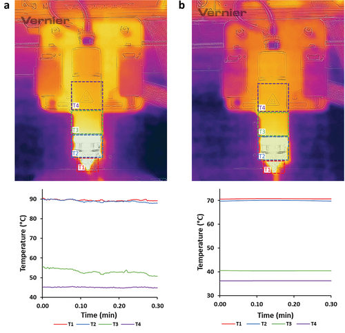
Table 3. Temperature ranges of the printhead, during printability studies.
Material extrusion can be modified and monitored by applying different pressure forces permitting the control of material flow through the nozzle. Two different pressures were used to evaluate the processability of solid rasters, during printability studies. It was observed that when the melted material was less viscous, less pressure was required for material extrusion and printing [Citation42].
Furthermore, printing speed is defined by two individual velocities, the traveling speed and the printhead speed [Citation42]. Printing speed was adjusted to 1 mm/s and 2 mm/s for adequate extruded material flowability and continuous filament attachment to the printing surface. Moreover, 3DP design integrity was achieved by controlling the printhead’s moves before starting to travel and by determining the printing pre-flow time of the material. According to printability accuracy perspectives, the filament diameter equals the distance between the nozzle and the printbed offset. In this study, the filament diameter is nozzle diameter identified; thus, pre-flow time was determined by EquationEquation (8)(8)
(8) , when vtotal = vpump = vtraveling. Hence, material pre-flow time was adjusted and calculated to 840 ms.
where, d: diameter, v: velocity-
Overviewing melt temperature, pressure, and printing speed attributes, three different combinations of PPs were applied during printability studies; PP1 (TR1, 65 kPa and 1 mm/s), PP2 (TR2, 130 kPa and 1 mm/s) and PP3 (TR1, 130 kPa and 2 mm/s). PP1 was implemented for all SSs, PP2 was applied for SS1, SS2 and SS3 and PP3 was implemented only for SS4.
Structural features of the scaffolds were examined by optical microscopy () and revealed results concerning the fidelity between the experimental and the theoretical (digital) structure dimensions (EquationEquation 9(9)
(9) ). Positive values, regarding the SF of the pattern’s raster width, indicate swelling of the polymeric raster during printing extrusion. The swelling effect of rasters occurred due to the applied high pressure and high viscosity behavior of the materials during melt-extrusion. On the contrary, negative values of %SF of raster gaps denote a reduction of space between the rasters due to their swelling. Moreover, an equal raster and gap %SF scheme is observed, with an inverse correlation between raster width and gap in all different 3D printed SSs. Therefore, when comparing the SF of the rectilinear pattern, it is noticed that the difference between raster width and gap sum is apparently similar to the theoretical. In addition, an SF defines the uniformity and integrity of the structure regarding the digital geometrical characteristics, it is assumed that raster width and gap measurements reveal close values to the original, with >80% occurrence of accordance to the initial pattern [Citation49].
Figure 2. Optical microscope images illustrating (i) the raster width and gap dimensions and SEM-EDS microscope analysis depicting (ii) the surface and (iii) the elemental map of (a) SS1, (b) SS2, (c) SS3 and (d) SS4 3D extruded samples, respectively.
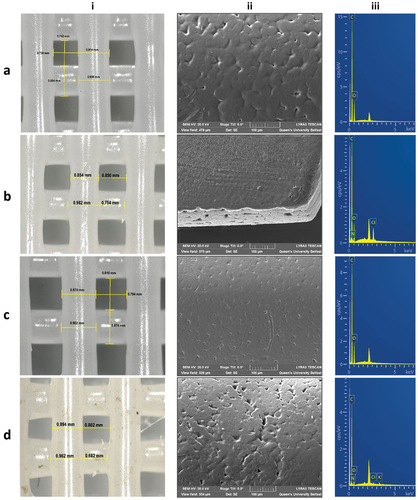
SEM images revealed surface morphological characteristics, regarding the surface topology, roughness, and pore formation of all extruded formulations (, Figure S3-supplementary material). Specifically, particle compaction was clearly depicted on extruded rasters’ surface, creating a uniform surface pore formation. The melting and extrusion temperature can affect a powder’s particle compaction, and hence impact pore size formation and particle homogeneity in the melting mixture [Citation43]. No specific difference in surface morphology was observed between the different scaffold formulations, owing to similar particle size of materials used, the low load %wt. of CS and PRC in the scaffold, and the close temperature ranges applied during printability studies.
EDS analysis was performed for the determination of all extruded scaffolds’ elemental composition. All spectra revealed the characteristic peaks of carbon (C) and oxygen (O), corresponding to PCL (/iii). In addition, nitrogen (N) and chloride (Cl) were detected on SS2 and SS4 formulations (/iii), confirming the existence of the hydrochloric salt of PRC distributed on specific areas of the samples; however, these elements were not identified on SS3 (/iii), due to possible evaporation of CS’s -NH2 groups throughout the melting procedure. Therefore, it is assumed that even though both CS and PRC were adequately mixed, they were not equally distributed into the polymeric matrix, owing to their low %wt. concentration [Citation50].
3.2. FTIR characterization
FTIR spectra of pure CS and PRC were compared with the PM5 FTIR spectrum (Figure S4A-supplementary material) to evaluate possible interactions, regarding their combination. The presence of PRC in PM5 is appeared through characteristic peaks of the aromatic ester C-O stretching in 1270 cm−1, the C-N stretching of the substituted aromatic amine in 1363 cm−1, the -NH2 scissoring absorption at 1605 cm−1, the conjugated C=C stretching bands of the benzol in 1645 cm−1, as well as the stretching of the aromatic ester C=O in 1691 cm−1. The spectrum also showed two characteristic bands in 2495 cm−1 and 2585 cm−1, denoting the appearance of tertiary amine salt NH+ stretch, and a characteristic peak in 3205 cm−1 of ammonium anions (because the HCl salt of PRC was used). On the other hand, characteristic bands for CS were appeared in 900 cm−1 defining the C-H bending out of the plane of the ring of monosaccharides, in 1154 cm−1 for the asymmetric stretching of the ether C-O-C bridge, in 1308 cm−1 showing the C-N stretching of the aromatic amine and in 3352 cm−1 for the stretching of O-H, formed by intramolecular H bonds [Citation46,Citation47].
Samples of the extruded formulations were analyzed through FTIR and compared to PM5, for the examination of CS and PRC presence into PCL matrices (Figure S4B-supplementary material). A strong band at 1722 cm−1 was appeared in all spectra, defining the carbonyl C=O stretching of PCL (53). Regarding SS2, PRC was evaluated through the characteristic bands at 1605 cm−1, 1645 cm−1, 3205 cm−1, and 3352 cm−1, as previously analyzed. Moreover, the appearance of CS in SS3 was determined through a slight peak at 3205 cm−1 denoting the stretching of ammonium anions. Last but not least, the presence of both CS and PRC were assessed by peaks at 1605 cm−1, 1645 cm−1, 2495 cm−1, 2585 cm−1, and 3205 cm−1, revealing their potential interaction, by forming intermolecular H bonds with PCL. The strength of CS and PRC absorbances in all spectra was weak, due to their low %wt. used in the formulation mixture [Citation46,Citation47].
3.3. Thermal analysis
TGA and DSC analysis were performed to describe the thermal properties of all raw materials, PMs, and extruded composites.
The melting temperature of PCL (Tm(PCL) = 66.3 ± 0.4°C) was considerably lower compared to CS (Tm(CS) = 166.0 ± 2.5°C) and PRC (Tm(PRC) = 162.8 ± 0.3°C) (). Contrarily PCL degraded at a higher temperature (Tdeg(PCL) = 426 ± 1°C), compared to other materials (Tdeg(CS) = 317 ± 3°C, Tdeg(PRC) = 298 ± 6 °C) (). Hence, the adjustment of printing temperature ranges (TR1 and TR2) did not significantly affect the thermal properties of CS and PRC during the melting procedure of PCL composite mixtures. Furthermore, composite scaffolds consisting of CS possessed a slightly faded yellow appearance (/i), due to initial thermal degradation of inter/intra-hydrogen bonds (9.0 ± 0.4% wt. loss, T = 72 ± 2°C), as well as the generation of carbon related by-products, associated to possible deacetylation of amine groups (Table S2-supplementary materials) [Citation51].
Figure 3. TGA thermograms of (a) PCL, CS, PRC, PM2, and PM4, and (b) all SSs and PMs. (c) STDSC thermograms of PCL, PRC, and CS, and (d) MTDSC thermograms of all SSs (first heat cycle) and PRC (second heat cycle).
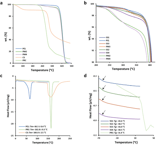
Furthermore, in all composite PMs (PM2, PM3, PM4), the impact of CS and PRC load was evaluated by TGA determination since it was not detected through DSC analysis due to their low %wt. in the PM (Table S2-supplementary material). All SSs and PMs showed similar Tdeg () and Tm; however, SSs were characterized by lower melting endotherm absolute values compared to PCL and PMs (PM2, PM3, and PM4) (Table S3-supplementary material). Therefore, it is concluded that polymer materials were not completely melted (Tprinting ≤ Tm(Endpoint)) and were partially recrystallized after melt-extrusion [Citation22].
Glass transition temperatures of both raw materials and scaffold samples were determined through MTDSC studies, subsequently, the Gordon-Taylor equation was applied to calculate the theoretical Tg values of SS2 and SS4, examining the miscibility of the drug into the scaffolds. MTDSC thermograms showed similar Tg for both SS2 (Tg(SS2) = −66.7°C) and SS4 (Tg(SS4) = −66.5°C), while their theoretical Tg values (Tg(SS2) = −60.8°C and Tg(SS4) = −58.9°C) were close to the experimental. The low concentration of PRC (1% wt.) permitted its complete miscibility and its amorphous state transition into the extruded solid dispersions.
3.4. Mechanical analysis
Stiffness of all scaffolds was tested until breakage, Young’s Modulus (E), Ultimate Tensile Strength (UTS), and Maximum Elongation (ME) were evaluated (). Examining the general profile of different materials used, all scaffolds seemed to break in similar loads (UTSmean = 4.35 ± 0.20) (), due to high PCL concentrations in all scaffolds. Moreover, composite scaffolds were classified by the resulting lowest resistance to longitudinal deformation (SS2: 2.49 ± 0.83, SS3: 2.00 ± 1.33, SS4: 1.73 ± 0.32), comparably to plain PCL scaffolds (SS1: 3.92 ± 0.80), possibly impacted by CS and PRC presence. Considering the low concentrations of CS and PRC in the scaffolds, slight differences were observed regarding scaffolds’ stiffness behavior; in particular, Young’s Modulus for SS1 (30.00 ± 0.47) resulted in lower values compared to composite samples (SS2: 33.93 ± 6.36, SS3: 30.35 ± 5.14, SS4: 38.35 ± 2.64) [Citation22]. The addition of the natural polymer CS and the API affected the ductility of the final structure, likely due to their different MW and solid amorphous form to PCL. Furthermore, the results demonstrated that plastic deformation of each scaffold is related to their dimensions and the rectilinear infill pattern, since depicted peaks on stress-stain curves () define the stretching of vertically printed rasters. Therefore, final stiffness characteristics of all fabricated scaffolds are defined to be durable and tough, with adequate mechanical properties, which can be potentially applied as effective DDSs for hard tissues [Citation52].
Figure 4. (a) Stress-strain curves and (b) bar chart of Young’s modulus (E), ultimate tensile strength (UTS), and maximum elongation (ME) values of SS1, SS2, SS3, and SS4 3D printed scaffold samples, respectively (n = 5).
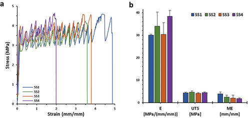
Table 4. Evaluation of E, UTS, and ME mechanical parameters of SS1, SS2, SS3, and SS4 3D printed scaffold samples (n = 5).
3.5. In vitro drug release studies
PRC release profiles through solid (SS2) and composite (SS4) polymeric 3D printed scaffolds were examined and evaluated (). This study primarily focuses on the in vitro release profiles of the API. It is important to clarify that no investigations into the in vivo release kinetics of the API, or the assessment of toxicity levels associated with both the polymers and the API are included.
Figure 5. In vitro % release of procaine hydrochloride (PRC HCl) vs. time (SS2 and SS4 extruded scaffolds) at PBS medium (t= 0–168 h). The results denote the mean value (n= 4, SEM < 2) and are normalised to the %wt. Of the loaded amount of the API.
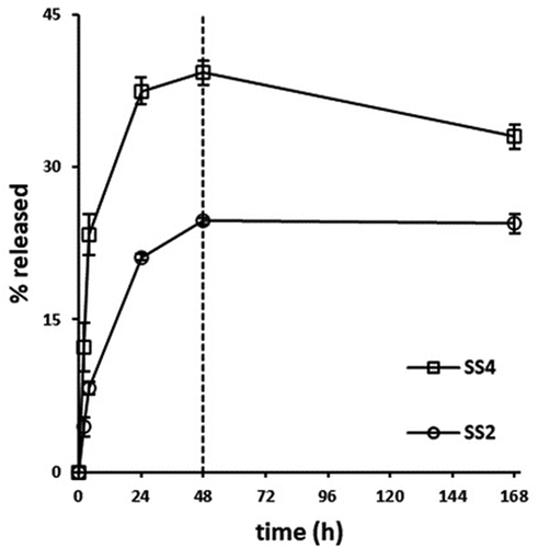
Obtained results regarding SS2 formulation denoted an initial burst release during the first 24 h (21.12%), followed by a moderate increase, reaching its maximum value at 48 h (24.71%), subsequently, a plateau was formed up to 7 days. PCL contributes to delaying the drug release, due to its substantially hydrophobic nature, acquired from its long lipophilic chains (Figure S5A-supplementary material). On the contrary, PRC is an amphiphilic drug (aromatic -NH2: pKa1 = 2.5, aliphatic -NH2: pKa2 = 9.0, water solubility: 5 mg/mL); thus, in the aqueous PBS medium (pH 7.4) the aliphatic -NH2 is ionized, rather than the aromatic -NH2 being unionized, due to delocalization of the amine’s electron pair into the ring [Citation53]. It is assumed that the drug interacts with the hydrophobic aromatic ring within the chains of the PCL, which enhances its entrapment into the polymeric system and prolongs its release (Figure S5B-supplementary material) [Citation46]. The release mechanism from SS2 (n = 0.46) indicates a non-Fickian pattern, described from combined phenomena of pure diffusion and Case II transport [Citation54], due to interactions developed through intermolecular forces, between the dissolution medium ions and the scaffold surface (). In particular, dissolution media molecules may interact with the amorphous phase of the polymeric surface, stimulating the fragmentation of tie-chain segments, consequently, permitting water penetration, and allowing PRC’s release. Moreover, the low concentration of PRC in the formulation may affect its total release levels from PCL matrix, due to small amount of PRC molecules entrapped into polymeric chain regions, that are vulnerable to dissolution medium molecule interactions [Citation55].
Table 5. Drug release kinetics of procaine from the 3D printed extruded scaffolds, following the Ritger-Peppas mathematical modeling approach.
Examining PRC’s release rate from SS4 formulations, an initial steep increase is observed during the first 24 h (37.49% drug released), followed by a steady increase and finally reaching its highest value at 48 h (39.27%) (). As referred also in § 2.2.1. the use of CS indicates an enhanced PRC release from SS4 extruded samples. The water solubility of CS corresponds to its ionization potential (pKa ≈ 6.3), which is relative to the degree and the method of its deacetylation (Figure S5D-supplementary material). The amount and the distribution of free -NH2 groups in its structure can define its capability of interacting and/or releasing the active substance [Citation53]. Hence, it is assumed that CS, as a polysaccharide, reacts with the PRC hydrophilic -NH2 group (Figure S5A-supplemntary material) in a way that facilitates primarily its dissolution rate from PCL matrixes, subsequently contributing to its 7-day extended release [Citation56]. More specifically, CS’s -NH2 and -OH ligands may form hydrogen bonds with PRC’s functional groups, leading to its more controllable release (Figure S5C-supplementary material). Moreover, the length of this polymer’s chain is crucial to its solubility. In particular, low MW CS appears to be more soluble, possibly, due to random arrangement of N-acetyl groups in its chain. These structure modifications affect the polymer’s conformation, by reducing intermolecular attraction forces (e.g. van der Waals), making the polymer more vulnerable to hydration forces [Citation57]; thus, influencing PRC’s entrapment capacity in the polymeric mixture and enhancing its release [Citation26]. As a result, low concentrations of CS (3% wt.) may not influence vastly the final PRC’s release mechanism, due to PCL’s greater amount in SS4 formulations; however, higher % release levels reveal a Fickian release mechanism (n = 0.29) described by a diffusive regime [Citation27,Citation58].
Furthermore, a notably extended release rate is observed for SS2 and SS4 formulations during dissolution studies, by releasing their maximum % drug after 48 h, which can characterize the release potency as prolonged, considering the short half-life of PRC (~15–20 min) [Citation59]. Drug content studies revealed a drug recovery of 1.44 ± 0.1 mg (with an avg. scaffold weight of 100 mg) from the loaded samples. Therefore, dissolution studies determined that 75.29% and 60.73% interacted with the polymeric matrices of SS2 and SS4, respectively, as per EquationEquation 6(6)
(6) (§ 2.2.6). Consequently, PCL impacts the total drug release in both SS2 and SS4, since it effectively entraps the API [Citation46]. The combination of two polymers in SS4 may affect the drug release rate, considering the solubility compatibility between the PBS dissolution medium and CS [Citation27,Citation58]. Therefore, CS in SS4 seems to enhance the solubility of the polymeric matrix, conducting toward a greater, almost twice (39.27%), dissolution rate of PRC [Citation26,Citation44].
4. Conclusions
In this research study, novel formulations were developed, with a perspective on simplifying current multimodal pain relief regimens. Empty and PRC loaded 3D printed scaffolds of PCL and PCL/CS composites were designed and developed. Physicochemical evaluation, concerning heating processing and chemical interactions of raw materials, PMs, and extruded samples did not show any significant evidence, regarding their stability and compatibility. Moreover, printability parameters were optimized. Scaffold dimensions were investigated to be similar to the theoretical CAD dimensions, developed through a mathematical model. Stiffness parameters of the scaffolds were characterized to be reproducible, corresponding to the rectilinear geometrical design. Furthermore, drug release studies were exclusively conducted in vitro, where a synergistic effect between PCL and CS was indicated, revealing an initial immediate release of PRC, succeeded by a 7-day extended increase. These models aim of laying the groundwork for the development of in vivo models (i.e. animal studies based on operative pain and pain assessment) to explore the pharmacodynamic and pharmacokinetic profile of the API, especially for local/distant drug release evaluation. Therefore, combinations of biocompatible and biodegradable polymeric composites have shown promising results in fabricating multifunctional implantable 3D printed DDSs, for post-operative analgesia treatment.
Abbreviations
3DP, 3D printing; ANOVA, one-way analysis of variance; API, Active Pharmaceutical Ingredient; ATR, attenuated total reflectance; CAD, Computer Aided Design; CPPs, Critical; Process Parameters; CQAs, Critical Quality Attributes; CS, chitosan; DDS, Drug Delivery System; DSC, Differential Scanning Calorimetry; E, Young’s modulus; EDS, energy-dispersive X-ray; FTIR, Fourier-transform infrared spectroscopy; HPLC, High Performance Liquid Chromatography; ME, maximum elongation; MTDSC, Modulated DSC; MW, Molecular Weight; NMDA, N-methyl-D-aspartate; NMP, N-Methyl-2-pyrrolidone; NSAIDs, nonsteroidal anti-inflammatory drugs; PBS, Phosphate Buffer Saline; PCL, polycaprolactone; PEG, polyethylene glycol; PLGA, polylactic-co-glycolic acid; PM, Physical Mixture; PP, Printing Parameter; PRC·HCl, procaine hydrochloride; PU, polyurethane; SEM, Scanning Electron Microscope; SEM, Standard Error of the Mean; SF, Shape Fidelity; SLA: stereolithography; SS, Scaffold Sample; STDSC, Standard DSC; TAU-R, time constant and thermal resistances; Tdeg, degradation temperature; Tg, glass transition temperature; TGA, Thermogravimetric Analysis; Tm, melting temperature; UTS, ultimate tensile strength; ΔCp, heat capacity change.
Author contributions
Conception and design, A Dedeloudi, L Martinez-Marcos, T Quinten, S Andersen, D Lamprou; Analysis and interpretation of the data, A Dedeloudi; Funding acquisition, S Andersen, D Lamprou; Supervision, S Andersen, L Martinez-Marcos, D Lamprou; Methodology, A Dedeloudi, L Martinez-Marcos, T Quinten, S Andersen, D Lamprou; Writing – original draft preparation, A Dedeloudi; Writing – review and editing, A Dedeloudi, L Martinez-Marcos, T Quinten, S Andersen, D Lamprou; Final approval of the version to be published, A Dedeloudi, L Martinez-Marcos, T Quinten, S Andersen, D Lamprou; All authors agree to be accountable for all aspects of the work.
Declaration of interest
The authors have no relevant affiliations or financial involvement with any organization or entity with a financial interest in or financial conflict with the subject matter or materials discussed in the manuscript. This includes employment, consultancies, honoraria, stock ownership or options, expert testimony, grants, or patents received or pending, or royalties.
Reviewer disclosures
Peer reviewers on this manuscript have no relevant financial or other relationships to disclose.
2024.01.03. Dedeloudi et al. 2024. Supplementary material (original).docx
Download MS Word (642.7 KB)Acknowledgments
The authors would like to thank Janssen Pharmaceutica and the Engineering and Physical Sciences Research Council (EPSRC) for providing the PhD studentship to AD.
Supplementary material
Supplemental data for this article can be accessed online at https://doi.org/10.1080/17425247.2024.2336492
Additional information
Funding
References
- Passik SD. Issues in long-term opioid therapy: unmet needs, risks, and solutions. Mayo Clin Proc. 2009;84(7):593–601. doi: 10.1016/S0025-6196(11)60748-9
- Buvanendran A, Kroin JS. Multimodal analgesia for controlling acute postoperative pain. Curr Opin Anaesth. 2009;22(5):588–593. doi: 10.1097/ACO.0b013e328330373a
- Stephy G, Johns M. Review of nonopioid multimodal analgesia for surgical and trauma patients. Am J Health Syst Pharm. 2020;77(24):2052–2063. doi: 10.1093/ajhp/zxaa301
- Quarterman JC, Geary SM, Salem AK. Evolution of drug-eluting biomedical implants for sustained drug delivery. Eur J Pharm Biopharm. 2021;159:21–35. doi: 10.1016/j.ejpb.2020.12.005
- Santos A, Sinn Aw M, Bariana M, et al. Drug-releasing implants: Current progress, challenges and perspectives. J Mater Chem B. 2014;2(37):6157–6182. doi: 10.1039/C4TB00548A
- Benhabbour SR, Kovarova M, Jones C, et al. Ultra-long-acting tunable biodegradable and removable controlled release implants for drug delivery. Nat Commun. 2019;10(1):4329. doi: 10.1038/s41467-019-12141-5
- Elkasabgy NA, Mahmoud AA. Review article fabrication strategies of scaffolds for delivering active ingredients for tissue engineering. AAPS Pharm Sci Tech. 2019;20(7):256. doi: 10.1208/s12249-019-1470-4
- Sharifi F, Atyabi SM, Norouzian D, et al. Polycaprolactone/Carboxymethyl chitosan nano fibrous scaffolds for bone tissue engineering application. Int J Biol Macromol. 2018;115:243–248. doi: 10.1016/j.ijbiomac.2018.04.045
- Kumar A, Pillai J. Chapter 13: implantable drug delivery systems: an overview. Elsevier I. Nanostructures for the engineering of cells, tissues and organs. Elsevier Inc.; 2018. https://shop.elsevier.com/books/nanostructures-for-the-engineering-of-cells-tissues-and-organs/grumezescu/978-0-12-813665-2
- Fernandes C, Suares D, Dhawan V, et al. Tissue engineering technology. Fundamentals of nanoparticles. Elsevier Inc.; 2018. p. 451–483. https://www.sciencedirect.com/book/9780323328890/nanotechnology-applications-for-tissue-engineering
- Adamo JE, Grayson WL, Hatcher H, et al. Regulatory interfaces surrounding the growing field of additive manufacturing of medical devices and biologic products. J Clin Transl Sci. 2018;2(5):301–304. doi: 10.1017/cts.2018.331
- Später T, Mariyanats AO, Syachina MA, et al. In vitro and in vivo analysis of adhesive, anti-inflammatory, and proangiogenic properties of novel 3D printed hyaluronic acid glycidyl methacrylate hydrogel scaffolds for tissue engineering. ACS Biomater Sci Eng. 2020;6(10):5744–5757. doi: 10.1021/acsbiomaterials.0c00741
- Maturavongsadit P, Paravyan G, Kovarova M, et al. A new engineering process of biodegradable polymeric solid implants for ultra-long-acting drug delivery. Int J Pharm X. 2021;3:100068. doi: 10.1016/j.ijpx.2020.100068
- Lee C-F, Hsu Y-H, Lin YC, et al. 3D printing of collagen/oligomeric proanthocyanidin/oxidized hyaluronic acid composite scaffolds for articular cartilage repair. 3D printing of collagen/oligomeric proanthocyanidin/oxidized hyaluronic acid composite scaffolds for articular cartilage repair. Polymers. 2021;13:3123.
- Gutierrez E, Burdiles PA, Quero F, et al. 3D printing of antimicrobial alginate/Bacterial-cellulose composite hydrogels by incorporating copper nanostructures. ACS Biomater Sci Eng. 2019;5(11):6290–6299. doi: 10.1021/acsbiomaterials.9b01048
- Johnson LM, Krovi SA, Li L, et al. Characterization of a reservoir-style implant for sustained release of tenofovir alafenamide (TAF) for HIV pre-exposure prophylaxis (PrEP). Pharmaceutics. 2019;11(7):11. doi: 10.3390/pharmaceutics11070315
- Lam CXF, Hutmacher DW, Schantz JT, et al. Evaluation of polycaprolactone scaffold degradation for 6 months in vitro and in vivo. J Biomed Mater Res A. 2009;90(3):906–919. doi: 10.1002/jbm.a.32052
- Ma Z, Wang Q, Xie W, et al. Performance of 3D printed PCL/PLGA/HA biological bone tissue engineering scaffold. Polym Compos. 2021;42(7):3593–3602. doi: 10.1002/pc.26081
- de Moura NK, Siqueira IAWB, Machado JDB, et al. Production and characterization of porous polymeric membranes of PLA/PCL blends with the addition of hydroxyapatite. J Compos Sci. 2019;3(2):3. doi: 10.3390/jcs3020045
- Hsieh YH, Shen BY, Wang YH, et al. Healing of osteochondral defects implanted with biomimetic scaffolds of poly(ε-caprolactone)/hydroxyapatite and glycidyl-methacrylate-modified hyaluronic acid in a minipig. Int J Mol Sci. 2018;19(4):1125. doi: 10.3390/ijms19041125
- Kim MH, Yun C, Chalisserry EP, et al. Quantitative analysis of the role of nanohydroxyapatite (nHA) on 3D-printed PCL/nHA composite scaffolds. Mater Lett. 2018;220:112–115. doi: 10.1016/j.matlet.2018.03.025
- Corduas F, Mathew E, McGlynn R, et al. Melt-extrusion 3D printing of resorbable levofloxacin-loaded meshes: emerging strategy for urogynaecological applications. Mater Sci Eng C. 2021;131:112523. doi: 10.1016/j.msec.2021.112523
- Azimi B, Nourpanah P, Rabiee M, et al. Poly (∊-caprolactone) fiber: an overview. J Eng Fiber Fabr. 2014;9(3):74–90. doi: 10.1177/155892501400900309
- Dash M, Chiellini F, Ottenbrite RM, et al. Chitosan—A versatile semi-synthetic polymer in biomedical applications. Prog Polym Sci. 2011;36(8):981–1014. doi: 10.1016/j.progpolymsci.2011.02.001
- Intini C, Elviri L, Cabral J, et al. 3D-printed chitosan-based scaffolds: an in vitro study of human skin cell growth and an in-vivo wound healing evaluation in experimental diabetes in rats. Carbohydr Polym. 2018;199:593–602. doi: 10.1016/j.carbpol.2018.07.057
- Rusu AG, Chiriac AP, Nita LE, et al. Interpenetrated polymer network with modified chitosan in composition and self-healing properties. Int J Biol Macromol. 2019;132:374–384. doi: 10.1016/j.ijbiomac.2019.03.136
- Di Luca M, Hoskins C, Corduas F, et al. 3D printed biodegradable multifunctional implants for effective breast cancer treatment. Int J Pharm. 2022;629:122363. doi: 10.1016/j.ijpharm.2022.122363
- Becker DE, Reed KL. Essentials of local anesthetic pharmacology. Anesth Prog. 2006;53(3):98–109. doi: 10.2344/0003-3006(2006)53[98:EOLAP]2.0.CO;2
- Wolfe RC, Spillars A. Local anesthetic systemic toxicity: reviewing updates from the American society of regional anesthesia and pain medicine practice advisory. J PeriAnesthesia Nurs. 2018;33(6):1000–1005. doi: 10.1016/j.jopan.2018.09.005
- Reuter UR, Oettmeier R, Nazlikul H. Procaine and procaine-base-infusion: a review of the safety and fields of application after twenty years of use. Clin Res Open Access. 2018;4(1):1–7. doi: 10.16966/2469-6714.127
- Fan X, Yang H, Zhao C, et al. Local anesthetics impair the growth and self-renewal of glioblastoma stem cells by inhibiting ZDHHC15-mediated GP130 palmitoylation. Stem Cell Res Ther. 2021;12(1):1–16. doi: 10.1186/s13287-021-02175-2
- Zhu G, Zhang L, Dan J, et al. Differential effects and mechanisms of local anesthetics on esophageal carcinoma cell migration, growth, survival and chemosensitivity. BMC Anesthesiol. 2020;20(1):20. doi: 10.1186/s12871-020-01039-1
- Mathew E, Pitzanti G, Larrañeta E, et al. Three-dimensional printing of pharmaceuticals and drug delivery devices. Pharmaceutics. 2020;12(3):266–269. doi: 10.3390/pharmaceutics12030266
- Farmer ZL, Utomo E, Domínguez-Robles J, et al. 3D printed estradiol-eluting urogynecological mesh implants: influence of material and mesh geometry on their mechanical properties. Int J Pharm. 2021;593:120145. doi: 10.1016/j.ijpharm.2020.120145
- Wu Q, Therriault D, Heuzey MC. Processing and properties of chitosan inks for 3D printing of hydrogel microstructures. ACS Biomater Sci Eng. 2018;4(7):2643–2652. doi: 10.1021/acsbiomaterials.8b00415
- Xing F, Zhou C, Hui D, et al. Hyaluronic acid as a bioactive component for bone tissue regeneration: fabrication, modification, properties, and biological functions. Nanotechnol Rev. 2020;9(1):1059–1079. doi: 10.1515/ntrev-2020-0084
- Konta AA, García-Piña M, Serrano DR. Personalised 3D printed medicines: which techniques and polymers are more successful? Bioengineering. 2017;4(4):4. doi: 10.3390/bioengineering4040079
- Park BJ, Choi HJ, Moon SJ, et al. Pharmaceutical applications of 3D printing technology: current understanding and future perspectives. J Pharm Investig. 2019;49:575–585. doi: 10.1007/s40005-018-00414-y
- Weaver E, O’Hagan C, Lamprou DA. The sustainability of emerging technologies for use in pharmaceutical manufacturing. Expert Opin Drug Deliv [Internet]. 2022;19:861–872. doi: 10.1080/17425247.2022.2093857
- NOVOCAIN®: procaine hydrochloride injection, USP. [cited 2023 Jan 24]. Available from: https://dailymed.nlm.nih.gov
- van der Merwe J, Steenekamp J, Steyn D, et al. The role of functional excipients in solid oral dosage forms to overcome poor drug dissolution and bioavailability. Pharmaceutics. 2020;12(5):12. doi: 10.3390/pharmaceutics12050393
- Naghieh S, Chen X. Printability–A key issue in extrusion-based bioprinting. J Pharm Anal. 2021;11(5):564–579. doi: 10.1016/j.jpha.2021.02.001
- Oladeji S, Mohylyuk V, Jones DS, et al. 3D printing of pharmaceutical oral solid dosage forms by fused deposition: the enhancement of printability using plasticised HPMCAS. Int J Pharm. 2022;616:121553. doi: 10.1016/j.ijpharm.2022.121553
- Quinten T, Andrews GP, De Beer T, et al. Preparation and evaluation of sustained-release matrix tablets based on metoprolol and an acrylic carrier using injection moulding. AAPS Pharm Sci Tech. 2012;13(4):1197–1211. doi: 10.1208/s12249-012-9848-6
- Kashimbetova A, Slamecka K, Casas-Luna M, et al. Implications of unconventional setting conditions on the mechanical strength of synthetic bone grafts produced with self-hardening calcium phosphate pastes. Ceram Int. 2022;48(5):6225–6235. doi: 10.1016/j.ceramint.2021.11.163
- Bennabi L, Abiras HW, Belarbi L, et al. Effect of polymer blends and evaluation from controlled release procaine hcl loaded poly(ε- caprolactone) microsphers. Biointerface Res Appl Chem. 2016;6:1483–1490.
- Montagnat OD, Webster GR, Bulitta JB, et al. Lessons learned in the development of sustained release penicillin drug delivery systems for the prophylactic treatment of rheumatic heart disease (RHD). Drug Deliv Transl Res. 2018;8(3):729–739. doi: 10.1007/s13346-018-0482-z
- Ritger PL, Peppas NA. A simple equation for description of solute release II. Fickian and anomalous release from swellable devices. J Controlled Release. 1987;5:37–42. doi: 10.1016/0168-3659(87)90035-6
- Schwab A, Levato R, D’Este M, et al. Printability and shape fidelity of bioinks in 3D bioprinting. Chem Rev. 2020;120(19):11028–11055. doi: 10.1021/acs.chemrev.0c00084
- Enderami SE, Shafiei SS, Shamsara M, et al. Evaluation of osteogenic differentiation of bone marrow-derived mesenchymal stem cell on highly porous polycaprolactone scaffold reinforced with layered double hydroxides nanoclay. Front Bioeng Biotechnol. 2022;10:10. doi: 10.3389/fbioe.2022.805969
- Zhang Y, Liu B, Wang L, et al. Preparation, structure and properties of acid aqueous solution plasticized thermoplastic chitosan. Polymers. 2019;11(5):11. doi: 10.3390/polym11050818
- Wang F, Tankus EB, Santarella F, et al. Fabrication and characterization of PCL/HA filament as a 3D printing material using thermal extrusion technology for bone tissue engineering. Polymers. 2022;14(4):14. doi: 10.3390/polym14040669
- Pillai CKS, Paul W, Sharma CP. Chitin and chitosan polymers: chemistry, solubility and fiber formation. Prog Polym Sci (Oxford). 2009;34(7):641–678. doi: 10.1016/j.progpolymsci.2009.04.001
- Sandra S, Diban N, Urtiaga A. Hydrolytic degradation and mechanical stability of poly (ε-Caprolactone)/Reduced graphene oxide membranes as scaffolds for in vitro neural tissue regeneration. Membranes. 2018;8(1):12. doi: 10.3390/membranes8010012
- Weems AC, Pérez-Madrigal MM, Arno MC, et al. 3D printing for the clinic: examining contemporary polymeric biomaterials and their clinical utility. Biomacromolecules. 2020;21(3):1037–1059. doi: 10.1021/acs.biomac.9b01539
- Panić J, Tot A, Drid P, et al. Design and analysis of interactions in ionic liquids based on procaine and pharmaceutically active anions. Eur J Pharmaceut Sci. 2021;166:105966. doi: 10.1016/j.ejps.2021.105966
- Alfaro L, Chotiko A, Chouljenko A, et al. Development of water-soluble chitosan powder and its antimicrobial effect against inoculated listeria innocua NRRL B-33016 on shrimp. Food Control. 2018;85:453–458. doi: 10.1016/j.foodcont.2017.10.023
- Ioannou N, Luo J, Qin M, et al. 3D-printed long-acting 5-fluorouracil implant to prevent conjunctival fibrosis in glaucoma. J Pharm Pharmacol. 2023;75(2):276–286. doi: 10.1093/jpp/rgac100
- Abdelkader H, Fathalla Z, Seyfoddin A, et al. Polymeric long-acting drug delivery systems (LADDS) for treatment of chronic diseases: inserts, patches, wafers, and implants. Adv Drug Deliv Rev. 2021;177:113957. doi: 10.1016/j.addr.2021.113957