
ABSTRACT
Introduction
Cardiac resynchronization therapy (CRT) is an important option in modern cardiac implantable electronic device (CIED) treatment. Techniques for left ventricular (LV) lead placement in the coronary sinus and its tributaries are neither well described nor studied systematically, despite attention regarding where to place the LV lead.
Areas covered
This review presents specialized tools and techniques to overcome some of the most common problems encountered in LV lead placement in CRT. These tools and techniques are termed Interventional CRT (I-CRT), as they share technology with other interventional procedures. The main principle in I-CRT, compared to the traditional over-the-wire technique, is to add better support for delivery of the LV lead through dedicated inner catheters that also allows more flexibility with the use of more guidewires and better imaging with direct venography in the target vein.
Expert opinion
Even though CRT is an established therapeutic option, there are still many challenges in the implementation of the therapy. The cornerstone should be an ease of delivering the CRT and specifically implantation of the LV lead. Therefore, knowledge of the principles in I-CRT is necessary, as I-CRT could make implantation simpler in general and easier to reach the optimal LV pacing site.
1. Introduction
1.1. Cardiac resynchronization therapy
Cardiac implantable electronic devices (CIEDs) are an established treatment for patients with a variety of cardiac arrhythmias. CIED includes cardiac resynchronization therapy (CRT), also known as biventricular pacing. CRT is an important therapeutic advancement in patients with heart failure, bundle branch block, and reduced ejection fraction [Citation1]. The essence of CRT is biventricular pacing, which aims to resynchronize contraction of the ventricles by endocardial pacing of the right ventricle (RV) and epicardial pacing of the left ventricle (LV) using a pacing lead placed in a side branch of the coronary sinus (CS) [Citation2]. CRT improves cardiac performance, reduces heart failure symptoms, and furthermore reduces mortality [Citation3,Citation4]. In the recent “ESC Guidelines on cardiac pacing and cardiac resynchronization therapy,” CRT is now established as a class I (A) indication in the left bundle branch block (LBBB) with a QRS duration > 150 ms in patients with sinus rhythm and a class II (A) indication in heart failure patients with a significant portion of RV pacing [Citation5]. Despite this evidence, several studies reported that some patients experience a clinical deterioration after CRT implantation [Citation6,Citation7]. Even though guideline criteria for CRT have been met, no clinical improvement can be measured after CRT in up to 30–40% of the patients who are considered the so-called nonresponders [Citation5,Citation6,Citation8].
1.2. Left ventricular pacing in CRT
The location of the left ventricular pacing lead (LV lead) is an important factor for obtaining a successful CRT response [Citation6,Citation8]. Multiple observational studies have shown that placement of the LV lead in the midportion or basal segment of a lateral or posterior-lateral target branch is associated with more efficient CRT as compared to placement of the LV lead in other regions such as apically or anteriorly [Citation3,Citation8–10]. Placement of the LV lead in the posterolateral nonapical regions results in pacing of the latest activated sites of the left ventricle, which is associated with greater CRT response rates [Citation10,Citation11].
Successful implantation and placement of the LV lead can be a challenging task due to anatomical variations or limitations and anatomical abnormalities. Earlier, it was shown that placement of LV leads through the CS has failure rates ranging from 7.5% to 10% [Citation4]. Knowing the tools for solving the unusual and/or difficult case of LV lead placement may bring down failure rates and lead to more patients receiving a successful CRT implantation, known to reduce risk of death and hospitalization [Citation3,Citation11].
2. Left ventricular lead implantation in CRT
2.1. Traditional approach
Traditional approaches for LV lead placement with the over-the-wire technique (OTW) have been developed and employed with the aim of reaching an optimal LV lead placement in more patients with greater CRT responder rates and thus better outcomes. Achieving successful LV lead placement requires several steps including CS localization, CS cannulation, access to the target branch, and LV lead advancement, all of which may pose challenges Citation4. The standard kit for delivering leads to the CS is usually provided by the CIED manufacturer. The major companies within the field of CIED all have dedicated sheaths and inner catheters as well as a multitude of LV leads in different shapes to accommodate different shapes of target veins. The challenge for the operator is to become familiar with the equipment from all companies and the many shapes of leads to choose from. Additionally, the dimensions of the delivery sheath provided by the CIED manufacturer only offer limited opportunities for additional support wires along with either the lead or inner catheters. Furthermore, most inner catheters only have a short reach and thus only provide support for lead delivery in the very proximal part of a target vein.
2.2. Interventional CRT
2.2.1. Tools
Interventional CRT (I-CRT) is a relatively new concept that incorporates new methods to address some of the shortcomings mentioned above [Citation12,Citation13]. I-CRT is based on the use of specific tools and techniques originally employed by interventional cardiologists and radiologists and can be regarded as a supplement to the traditional OTW technique.
In this section, we will present the fundamentals of the I-CRT technique as employed in our institutions, as a method of implanting a lead wherever you want in the CS.
The backbone of the I-CRT kit is the combination of a CS introducer sheath (9F Worley Advanced Coronary Sinus Guide™, Merit Medical) and the lateral vein introducer (5.5F Worley Advanced Lateral Vein Introducer™, Merit Medical) with a vein selector, a contrast dye kit, and a J-shaped support guidewire (see ). The telescopic properties of this delivery system allow the inner catheter to be introduced deep into the target vein with the possibilities to obtain selective venography beyond the standard CS occlusive venography, subselect a desirable side branch with guidewires, and have better support for lead delivery. There is also ample room for having extra guidewires along with the vein introducer to achieve stability within the CS [Citation4,Citation12].
Figure 1. Tools for Interventional CRT. The figure displays the standard set of tools used for interventionalCRT: a CS introducer sheath (9F Worley Advanced Coronary Sinus Guide, Merit Medical), a lateral vein introducer (5.5F Worley Advanced Lateral Vein Introducer, Merit Medical) with a vein selector (Merit Medical), a contrast dye kit with a y-connector access port, an all-purpose guidewire (Asahi Sion Guidewire, 0.36 mm, Asahi), and an extra support guidewire (MAILMAN Guidewire, 0.36 mm, Boston Scientific). The upper insert shows three different shapes of the tip of the vein selector: vertical (top), renal (middle), and hook (bottom).The lower insert shows the tip of the CS introducer sheath, with the j-shaped support guidewire, and the lateral vein introducer along with a vein selector equipped with two guidewires.
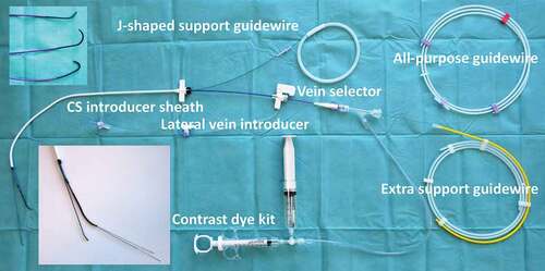
The interventional cardiologist and radiologist are used to have a wide variety of guidewires to access vessels and to provide support for delivery of devices, e.g. stents in the coronaries. It is important and valuable to discuss the challenges of navigating the CS anatomy with expert colleagues within interventional cardiology and thus select guidewires for I-CRT to track the tortuous venous system and a low tendency to perforate the vasculature. In our institution, we have chosen the Asahi Sion guidewire™ (0.36 mm) (Asahi) as the all-purpose guidewire, but this may be different in other institutions due to local experience and availability of equipment. The important point is that the implanter has knowledge of the possibilities provided by the different guidewires. When extra support is needed, e.g. for obtaining support for the vein introducer and vein selector in a narrow-angled take-off of a target vein, the Mailman guidewire™ (0.36 mm) (Boston Scientific) is our choice. These two guidewires are the preferred ones that we use in I-CRT.
In addition to the abovementioned standard equipment for I-CRT, a Snare kit (15 mm loop, 4 F, One Snare™, Merit Medical) is frequently used to lock a guidewire, thereby providing a firm rail to deliver the lead. More infrequently, the following equipment is taken into use:
A microcatheter for supporting the guidewire to reach the subselected branch in a target vein, e.g. Merit SureCross Support Catheter™, Merit Medical.
A multipurpose shaped guiding catheter for the right-sided or difficult CS access, e.g. Medtronic Launcher Guide Catheter™.
A venoplasty balloon for handling stenosis in the Superior Vena Cava, e.g. Advance™ 8 mm x 4 cm, Cook Medical.
2.2.2. Troubles in left ventricular lead placement
In the following sections, we will address some of the commonly encountered problems in CRT where I-CRT offers additional options beyond the traditional OTW approach. The challenges are presented in the chronological order that they appear stepwise during the implantation process, starting with access to the venous system and subsequently the CS, identification of the target vein, and finally delivery of the lead.
2.2.2.1. Access to and maneuverability in the venous system
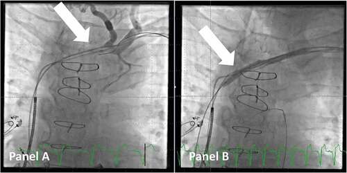
In some cases, there might be a stenotic part of the vasculature that either hinders the advancement of the delivery tools or impairs its movement to a degree, which makes implantation very difficult. This is often noted in patients with an existing transvenous system or after cardiac surgery. In such cases, venoplasty can be performed safely by the operator using a balloon dilatation catheter, e.g. Advance™ 8 mm x 4 cm, Cook Medical (see ). Navigating through the stenotic part can be challenging and often requires a micropuncture needle, e.g. S-AMK™, Merit Medical, and a contrast dye kit to visualize the lumen. It is advised as early as possible in the process to advance the wire below the diaphragm into the inferior caval vein to ensure that it is not in a false lumen. Gradually upsizing to a stiff guidewire to track the balloon can be done with a microcatheter, e.g. Impress Legato™ 4 F, Merit Medical. This method has proven to be safe [Citation14], and the time spent in performing the venoplasty early when the issue is first recognized is well invested as the rest of the lead placement is easier due to full maneuverability of the introducer sheath.
Figure 2. Venoplasty of a stenotic access to the superior caval vein. Panel A: venogram shows a stenotic part (arrow) of the venous access to the superior caval vein in a patient scheduled for upgrade to CRT. Panel B: A balloon (arrow) is used for venoplasty of the stenotic and fibrotic part of the venous system to gain access. Note that a guidewire is now in the right ventricular outflow tract.
If this method fails, the option of sacrificing a lead and using it for transvenous lead extraction to gain access to the venous system should be kept in mind.
2.2.2.2. Access to the CS ostium
Gaining access to the CS can sometimes be difficult. Using standardized equipment across multiple CIED systems can help the implanter to gain large routine with the same system for all implants instead of using different equipment delivered by the individual manufacturer. The standard CS access with the Worley standard CS guide has been described [Citation4,Citation15]. Access to the CS is not seldom challenging typically due to either anatomical abnormalities of the vasculature itself, the presence of a valve at the ostium, or unconventional positioning of the ostium due to extreme dilatation of the heart chambers. Furthermore, challenges may occur when the access route for the coronary sinus guide is unusual, e.g. when the venous access is from a right-sided vein (see ).
Figure 3. Access to the CS ostium from the right side (images in the right anterior oblique projection). Panel A: Due to enlarged right atrium, it is difficult to reach the ostium of the CS. A multipurpose guiding catheter is used, and two guidewires are inserted in the proximal part of the main CS, which is identified with a small volume of contrast. Note the large curve of the guiding catheter. Panel B: The wires are gently inserted deeper into the anterior part of the CS, and the multipurpose guiding catheter is also moved forward. Panel C: Contrast dye is injected to get an overview of the CS anatomy. Due to the sharp curve of the CS take-off and thus lack of stability of the system, it is not possible to move the outer coronary sinus guide forward. Panel D: More wires are added for extra support. Panel E: The outer coronary sinus guide can now be inserted into the main CS. Panel F: Selective venography distal in the CS identifies a possible target for placement of the lead.
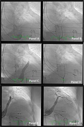
In such cases, it can be beneficial to use a multipurpose guiding catheter inside the CS guide, as this catheter can be shaped to accommodate the specific anatomy in, e.g., a large dilated right atrium. Another approach is to use either a steerable electrophysiology catheter or a hydrophilic guidewire, e.g. Radifocus™ Guide Wire, Terumo. Once the ostium is localized, it can be helpful to add multiple wires in the CS to obtain stability and support before advancing the coronary sinus guide. If it is very difficult to obtain stability, a standard PCI balloon in the anterior branch of CS can be used as an anchor for the advancement of the coronary sinus guide. Another method to gain CS access in difficult cases is to use the combination of a hydrophilic guidewire and an Amplatz Left II™ coronary catheter inside the CS guide. Most often, this telescopic tool enables smooth and atraumatic access to the CS.
Persistent left superior vana cava (SVC), where the venous flow from the left upper extremity is directed to the roof of the CS, presents a special challenge. While it is often possible to place a right atrial and right ventricular lead through the persistent left SVC, it can be very difficult to place a LV lead via this route. If such an anomaly is identified, it is most often easiest to change the access to the right side and place all leads from the right SVC.
2.2.2.3. Defining the CS anatomy
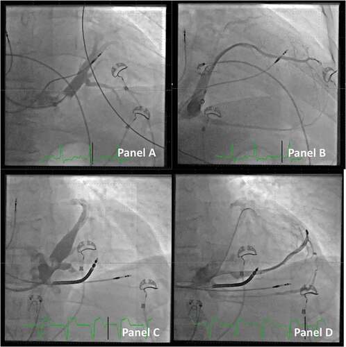
Once the CS is reached, it is necessary to define the anatomy of the CS with an occlusive venography in three projections (anterior-posterior, right anterior oblique, and left anterior oblique). This will point out where to seek the target vessels for LV lead implantation in the posterolateral position. It is however not always easy to get a full presentation of the entire CS vasculature even with a well placed balloon catheter, especially with respect to the most distal part of the tributaries. With the vein selector in the target vein, it is possible to perform a selective direct venography in the chosen vein, and this will most often reveal the distal part of the vein and whether collaterals to other vein branches are present (see ). A good outline of the target vein can thus guide subselection of an approachable side branch or identification of collaterals, which might be helpful in terms of having a guidewire pass through these, for better support when placing a lead OTW or even for using the snare technique to place the lead.
Figure 4. Defining the CS anatomy by direct venography. Panel A: Occlusive venogram in the main CS visualizing the distal part of the venous system (anterior-posterior projection).Panel B: the same patient as panel A. Selective direct venography of the chosen target vein displaying details of the vein including collaterals extending back to the middle cardiac vein (right anterior oblique projection).Panel C: Another patient with the occlusive venogram in the main CS. The venogram only shows the distal part of the venous system and is partially blocking the take-off of a large proximal vein.Panel D: The same patient as panel C. The proximal vein is targeted with the vein selector and guidewires, and a direct venography clearly delineates the outline of the vein including multiple collaterals. Note that the outer coronary sinus guide is kept in place in the CS despite the proximal position by extending the J-shaped support guidewire into the main CS toward the anterior part.
2.2.2.4. Access to the target vein
With the traditional OTW technique, the tip of the lead is most often used to steer into the target vein and then be advanced with a PCI guidewire at the frontend of the lead. In I-CRT, the aim is to place the lateral vein introducer in the target vein for delivery of the lead. The purposes are to subselect the target vein by, e.g., injecting contrast dye through direct selective venography and to facilitate the actual lead delivery as the diameter of the vein introducer is wide enough to allow introduction of most commonly used lead.
The telescopic tool of the I-CRT system consists of a) an outer coronary sinus guide, b) an inner lateral vein introducer, with c) a vein selector and d) a PCI guidewire(s) as the most inner part. Maneuvering of the different parts of the system allows us to safely access the take-off of the target branch. The vein selector comes with three different curvatures of the tip: a) vertical, b) renal, and c) hook, where the renal type fits most anatomies. Care should be taken not to inject contrast dye or advance the system when it is unclear whether the tip is not safely located in a proper lumen. This can be avoided by probing the actual position with a PCI guidewire and observing if it follows the anatomical outline from the occlusive venogram. It is valuable to note that the vein selector can hold multiple guidewires for obtaining additional support within the target vein (see ).
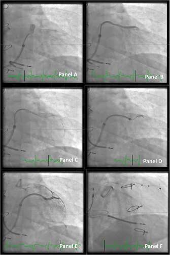
Figure 5. Access to the target vein in a patient undergoing CRT implant. Panel A: A vein selector is introduced. The take-off is sought by maneuvering the vein selector and injection of contrast dye (anterior-posterior projection).Panel B: The target branch is identified, and the vein selector is located in the proximal part of the vein.Panel C: A PCI wire is introduced in the vein selector. Panel D: An additional PCI wire is introduced and the LVI is telescoped in the vein. Panel E: A small volume of contrast dye is injected to ensure the distal part of the vein when the tip of the lead is expected to reach its final destination.Panel F: Final position of the lead (right anterior oblique projection).
2.2.2.5. Choosing the right and stable position for the lead
By defining the CS anatomy and getting access with the delivery system to the target vein, the destination for the lead can be selected. Some of the considerations to be aware of in this process are the following: is it possible to use a quadripolar lead to be placed into a stable position, not prone to dislodgement, and is the lead in an anatomically favorable position to pace the nonapical posterolateral part of the left ventricle? [Citation16,Citation17] To ensure these issues, it is self-evident that a complete overview of the CS anatomy and ability to reach all the possible targets with the delivery tools are imperative.If the implantation technique does not include these options, the operator is often forced to choose a lead to negotiate the given anatomy of the proximal part of the target vein, e.g. use a LV lead with a very wide curve or with an active fixation mechanism in a large diameter and/or noncurved vein, as it is not possible to be certain that the tip of a smaller curved passive fixation lead is fully wedged into a small side branch and thus securely placed (see ). Furthermore, if access to parts of the target vein is limited, it will potentially not be possible to locate the best pacing site with the longest sensed interventricular delay, lowest pacing threshold, and least likelihood of phrenic nerve stimulation. To reach a specific side branch in the target vein, skills well known when dealing with chronic occlusions in PCI may be needed. In such cases, it is advisable to discuss techniques with PCI colleagues. It can, e.g., be helpful to bend the tip of the PCI guidewire to access the side branch or to support the advancement of guidewires with a microcatheter.
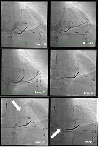
Figure 6. Choosing the right and stable position for the lead. Panel A: Direct venography through the vein selector shows a long, straight target vessel, without natural curvatures for fitting an s-formed quadripolar lead in a stable position. Panel B: When the venography is repeated with the vein selector in a deeper position, it then reveals several collaterals that may be a suitable target for the lead. Panel C: More wires are added to access the different veins, and with more wires comes more options for the final position. Panel D: A quadripolar lead is delivered OTW, but the tip is not inserted deep enough to be in a stable position. The guidewire used for OTW is through the collaterals back into the main CS. Panel E: The guidewire through the collateral back into the main CS is caught with a snare (arrow). Panel F: By applying a firm pull on the snare, the guidewire now serves as a better rail for pushing the lead forward to a wedged and stable position in the target branch. Note that the outer coronary sinus guide is retracted back to the right atrium to avoid bending of the wire (arrow).
One of the most important issues in such a situation may be to discuss which guidewires to use with your PCI colleagues. A guidewire with a hydrophilic tip that tends to go with the flow and with a low tip pressure to avoid perforation is well suited for I-CRT. In some special situations, guidewires with certain specific characteristics are needed, e.g. when extra support is needed or when a high tip pressure is necessary, when having to deal more ‘aggressively’ with a tight stenotic part in the superior vena cava.
2.2.2.6. Lead delivery beyond the standard OTW technique
When collaterals from the target vein to other parts of the CS are present, advancing a guidewire through these can provide several advantages. First, if the guidewire extends through collaterals, the shaft of the guidewire, which is stiffer than the distal part, will provide better support for advancement of the lead deeper into the target vein. Second, if the distal part of the wire is reachable, it can be caught with a snare and thus be kept in place with a pull from the operator on the distal part of the wire through the snare [Citation13]. There are some prerequisites for the snaring technique. The guidewire used should be with a shaft, which is resistant to the force of the snare, as a sharp bend on the guidewire may make it very difficult – if not impossible – to pull out the guidewire from the lead once it has reached the desired position (see ). Therefore, care should also be taken not to pull the snare with the wire into the coronary sinus guide, as it will inevitably create such a sharp bend on the wire. It is equally important to consider the character of the collaterals. A vessel with a diameter large enough to pass a guidewire but too small to accommodate a lead will not be suitable for snaring the lead, as the vessel will likely dissect. Applying too much force on such small vessels by pulling the snared PCI wire can create bigger lesions on the vasculature, potentially resulting in pericardial effusion.
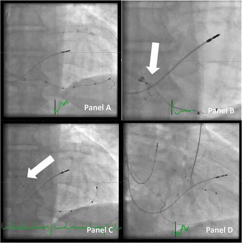
Figure 7. Delivery of a lead to the final position with the use of the snaring technique. Panel A: CRT in a patient in whom it was not possible to enter a posterolateral target branch. Instead, the middle cardiac vein was used, and collaterals connected it to the target vein as well as the anterior. A quadripolar lead was delivered using the OTW technique. Panel B: A snare catheter is inserted, and the tip of the guidewire is snared (arrow). Panel C: the looping guidewire between the lead and the snare is tightened with a pull on the snare, and the lead is advanced forward. Note that the tip of the outer coronary sinus guide is retracted to the right atrium (arrow), so the snare catheter is not pulled back into the coronary sinus guide and thus bending of the guidewire is avoided. Panel D: final position of the lead in the posterolateral position with the snare removed.
Choosing to snare the lead is not always clear from the first access into the target vein. If the standard PCI guidewire in use can also be used for snaring, progression to snare the wire can be applied straightforward if attempts of placing the lead according to desired position prove to be difficult. Sometimes, it is enough to create a good rail having the guidewire passing through collaterals, but the option of snaring remains open, as a next step.
Lead positioning using snaring procedures is more frequently performed by advancing the lead from the back end of the guidewire, the so-called orthodromic approach. However, in some rare instances, the guidewire can be pulled through the venous system, and back to the operator through the CS guide, to allow the lead to be advanced over an elongation of the guidewire, back in the CS, termed the antidromic approach.
Also, when maneuvering guidewires to allow snaring, it is very important to ensure that the tip of the guidewire is within the boundaries of the vessels and not in the pericardium. A prerequisite for this is a good roadmap of the vein system and especially the target vein, and the option to easily administer small amounts of contrast dye, while trying to pass the collaterals with guidewires.
2.2.2.7. Preventing and handling a dissection of the CS
The question often arises whether adding more catheters and guidewires in I-CRT more often causes dissection of the coronary sinus than what is seen in the traditional CRT technique. The CS vasculature can for sure be prone to damage and dissection if equipment is handled without the necessary caution [Citation18]. In general, the operator should always pay attention whenever advancing catheters and guidewires within the CS. If there is doubt whether the desired vessel is identified, the position can always be probed with a guidewire with a low tip-load, e.g. the previous mentioned Ashai Sion™ guidewire. If the guidewire cannot be advanced, or it does not track the natural course of the vasculature, or even causes ventricular premature beats, an extravascular position should be suspected, and care should be taken. When injection of contrast dye is done, it is important to always administer a very small volume (½-1 ml) before giving the full volume in the syringe, to ensure that the tip of the catheter, the balloon catheter, or the vein selector is not trapped in a small side branch or against the vessel wall, where a full dyeinjection may cause dissection. It is especially critical to be aware of the risk in injecting dye into the vein of Marshall, which often gives rise to entrapment of guidewires or catheters. Furthermore, always having a PCI wire in front of a stiff catheter when in the CS reduces the risk of perforation and dissection.
Despite these precautions, dissection can occur that may create difficulties and hinder the LV lead placement. Previously, cases were often abandoned, and patients were scheduled for a new procedure after some weeks, when the dissection had spontaneously resolved. With the I-CRT, it is often possible to bypass the affected part of the CS, with guidewires, and if they track the natural course of the venous system, e.g. the anterior part of CS, then a vein selector can be introduced and advanced past the dissected part of CS (see ). With a guidewire in the anterior branch of CS, access to other parts of CS can often be established even close to the dissected portion of CS because the proper CS lumen is always tracked by a guidewire that can track the delivery system.
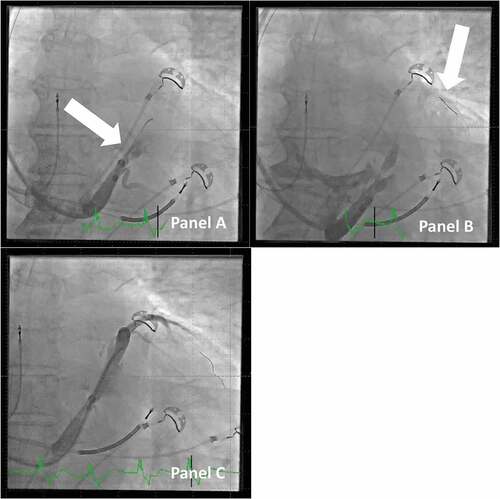
Figure 8. Dissection of the vein of marshall and how to proceed with lead implantation. Panel A: Injection of contrast dye in the CS, but with the j-shaped guidewire only in the vein of marshall (arrow). This creates a large dissection of the main CS. Panel B: The large dissection is clearly visible. A PCI guidewire (arrow) is passed by the part of CS with dissection onward to the anterior branch of CS. Panel C: A vein selector is tracked on the PCI guidewire across the part of CS with dissection, and contrast dye is injected to identify a probable target vein; the case can proceed despite the relatively large dissection.
2.2.2.8. Other considerations
The value of high-quality fluoroscopy equipment is essential in all CRT implants. As it is difficult to have the same level of fluoroscopy protection as, e.g., in coronary interventions, it is even more important to have a high level of discipline with regard to maintaining a low level of radiation dose [Citation19]. Angulated projections, right anterior oblique (RAO) and left anterior oblique (LAO), offerspecific details, which are important for the final result but also result in a higher radiation dose and poor ergonomic conditions for the operator. The LAO projection can be helpful if the CS is difficult to locate and to judge the position relative to the RV lead to ensure maximal anatomical spacing. The RAO offers the best profile fluoroscopy of the main target veins and therefore is well suited when judging the length of the lead tip into the vein branch. However, the anterior-posterior projection should be used as the main working projection due to lowering radiation exposure and for ergonomic reasons.
The device manufacturers offer a wide variety of leads in many shapes and lengths and some with an active fixation mechanism [Citation20]. With traditional CRT implantation, the right choice of lead was crucial, as it was often the shape of the lead that determined if it was possible even to get access to the target vein and to deliver the lead to the final and stable position. With I-CRT, the only question asked regarding the choice of lead is typically which length of the S-formed quadripolar lead to use [Citation17]. Quadripolar leads should be used by default, as this strategy is associated with less LV lead reoperations than bipolar LV leads and because use of quadripolar leads gives more reprogramming options during follow-up.
Finally, it is also important to know your equipment in detail and practice its intended use, e.g. snaring technique, to be able to solve difficulties during implants. In daily practice, a clinic often uses devices from two or more manufacturers, and each has developed its own set of delivery tools. If the implanter has to get acquainted with each of the tools with the subtle differences, it will be difficult to achieve routine and confidence with each and every set of delivery tools. It is therefore recommended to compose a standard kit of delivery tools in the clinic with a maximum of options that can be used across all implants.
3. Expert opinion
Given the many clinical studies on CRT in general and specific reviews on I-CRT, it is surprising that there is only a single systematic study on I-CRT compared to traditional CRT. In an observational study, Jackson et al. evaluated the effect of introducing I-CRT as compared to traditional CRT [Citation21]. They found that failed LV lead placement occurred less often and resulted in a significantly shorter fluoroscopy time, which is of utmost concern during CRT implantation. Furthermore, an optimal LV lead position was achieved more often with I-CRT. There are several trials comparing other methods, e.g. epicardial electrodes [Citation22], and other topics related to the actual hardware, e.g. multipoint pacing [Citation23].
The question of where to place the LV lead is still a matter of debate [Citation5]. Many observational and retrospective studies have investigated this matter, but there are only a few smaller prospective studies [Citation3,Citation24] without long-term follow-up on hard end points. A 1,000 patient randomized clinical trial currently is investigating whether targeting the latest electrically activated segment of the CS vein tree reduces the occurrence of the composite end point of death or unplanned hospitalization for heart failure (ClinicalTrials.gov NCT03280862). There is, however, no doubt that if the latest electromechanically activated site is pursued as the selected point for LV pacing [Citation25], so-called targeted CRT, either in daily clinical practice or as part of an investigation, the operator must have all the necessary means of both perioperative imaging and tools to reach all available potential pacing sites. In this regard, it is interesting that the investigators in the TARGET study [Citation3] only were able to position the LV lead at the optimal pacing site in 60% of the patients in the study arm randomized to targeted CRT.
The extra options provided by I-CRT are equally important, when CRT is compared to new and emerging conduction system pacing (CSP) modalities such as His bundle pacing (HBP) and left bundle branch area pacing [Citation5]. There are still no randomized controlled trials to prove the long-term efficacy and safety of CSP, and these new treatment concepts need further refinement and studying [Citation26,Citation27] in parallel with continuing optimization of CRT implant techniques.
Even though CRT is an established therapeutic option with proven benefits for many patients, there are still many challenges in the implementation of the therapy, as outlined recently in a European call for action on this matter [Citation28,Citation29]. The cornerstone should be an ease of delivering the CRT and specifically implantation of the LV lead. Therefore, knowledge of the principles in I-CRT may be a stepping stone for the individual physicians and institutions, who may be hesitating to offer CRT, as I-CRT could make implantation simpler in general and easier to reach the optimal LV pacing site. However, more observational or controlled studies are needed in this field to test this assumption.
Interventional CRT (I-CRT) is a set of tools and procedural techniques that adds extra options to the standard OTW technique in LV lead delivery in CRT.
The deep seated delivery tools provide a better overview of the CS anatomy including vein collaterals through direct venography and better possibility to subselect target veins. The snare technique further enhances lead delivery in difficult target vein access and lead placement to a stable position.
Finally, venoplasty and I-CRT can assist in the case of issues with access to and maneuverability in the venous system as well as procedure-related dissection in the CS vasculature.
Article highlights
Implantation of the left ventricular lead in the coronary sinus for pacing in cardiac resynchronization therapy (CRT) can be difficult with traditional implantation tools.
There are only very few systematic studies on implantation techniques.
InterventionalCRT (I-CRT) offers a number of tools and techniques, mainly based on telescoping sheaths with inner catheters, which provides better opportunities to visualize and getting access to all potential pacing sites for the left ventricular lead and support delivery of the LV lead in addition to the traditional over-the-wire technique.
A systematic approach to troubleshooting specific problems during the implantation process is presented.
General challenges in CRT treatment are discussed.
Declaration of Interest
The authors have no relevant affiliations or financial involvement with any organization or entity with a financial interest in or financial conflict with the subject matter or materials discussed in the manuscript. This includes employment, consultancies, honoraria, stock ownership or options, expert testimony, grants or patents received or pending, or royalties.
Reviewer disclosures
Peer reviewers of this manuscript have no relevant financial or other relationships to disclose.
Additional information
Funding
References
- Cleland JG, Daubert JC, Erdmann E, et al. Cardiac resynchronization-heart failure (CARE-HF) study investigators. the effect of cardiac resynchronization on morbidity and mortality in heart failure. N Engl J Med. 2005 Apr 14;352(15):1539–1549.
- Jarcho JA. Biventricular pacing. N Engl J Med. 2006Jul20;355(3):288–294.
- Khan FZ, Virdee MS, Palmer CR, et al. Targeted left ventricular lead placement to guide cardiac resynchronization therapy: the TARGET study: a randomized, controlled trial. J Am Coll Cardiol. 2012 Apr 24;59(17):1509–1518.
- Moss AJ, Hall WJ, Cannom DS, et al. MADIT-CRT trial investigators. cardiac-resynchronization therapy for the prevention of heart-failure events. N Engl J Med. 2009 Oct 1 ;361(14):1329–1338.
- Glikson M, Nielsen JC, Kronborg MB, et al. ESC Scientific Document Group ESC Guidelines on cardiac pacing and cardiac resynchronization therapy. Eur Heart J. 2021Sep14;42(35):3427–3520.
- Goldenberg I, Kutyifa V, Klein HU, et al. Survival with cardiac-resynchronization therapy in mild heart failure. N Engl J Med. 2014 May 1;370(18):1694–1701.
- Ruschitzka F, Abraham WT, Singh JP, et al. EchoCRTStudy Group. Cardiac-resynchronization therapy in heart failure with a narrow QRS complex. N Engl J Med. 2013 Oct 10;369(15):1395–1405.
- Kutyifa V, Kosztin A, Klein HU, et al. Left ventricular lead location and long-term outcomes in cardiac resynchronization therapy patients. JACC Clin Electrophysiol. 2018Nov;4(11):1410–1420.
- Katbeh A, Van Camp G, Barbato E, et al. Cardiac resynchronization therapy optimization: a comprehensive approach. Cardiology. 2019;142(2):116–128.
- Kronborg MB, Johansen JB, Riahi S, et al. An anterior left ventricular lead position is associated with increased mortality and non-response in cardiac resynchronization therapy. Int J Cardiol. 2016 Nov 1;222:157–162.
- Saba S, Marek J, Schwartzman D, et al. Echocardiography-guided left ventricular lead placement for cardiac resynchronization therapy: results of the speckle tracking assisted resynchronization therapy for electrode region trial. Circ Heart Fail. 2013May;6(3):427–434.
- Burkhardt JD, Wilkoff BL. Interventional electrophysiology and cardiac resynchronization therapy: delivering electrical therapies for heart failure. Circulation. 2007 Apr 24;115(16):2208–2220.
- Worley S, Ellenbogen KA. Application of interventional procedures adapted for device implantation: new opportunities for device implanters. Pacing Clin Electrophysiol. 2007Aug;30(8):938–941.
- Worley SJ. Challenging implants require tools and techniques not tips and tricks. Card Electrophysiol Clin. 2019Mar;11(1):75–87.
- Boey E, Tan ESJ, Yeo WT, et al. Coronary venoplasty during cardiac resynchronization therapy device implantations: acute results and clinical outcomes. Heart Rhythm. 2020May;17(5 Pt A):736–742.
- Zou F, Brar V, Worley SJ. Interventional device implantation, part i: basic techniques to avoid complications: a hands-on approach. J Cardiovasc Electrophysiol. 2021Feb;32(2):523–532.
- Butter C, Georgi C, Stockburger M. Optimal crt implantation-where and how to place the left-ventricular lead? Curr Heart Fail Rep. 2021Oct;18(5):329–344.
- Fyenbo DB, Park Frausing MHJ, Kronborg MB. Bipolar versus quadripolar left ventricular leads for cardiac resynchronization therapy: evidence to date. Expert Rev Cardiovasc Ther. 2021Dec;19(12):1075–1084.
- Chahine J, Baranowski B, Tarakji K, et al. Cardiac venous injuries: procedural profiles and outcomes during left ventricular lead placement for cardiac resynchronization therapy. Heart Rhythm. 2020Aug;17(8):1298–1303.
- Heidbuchel H, Wittkampf FH, Vano E, et al. Practical ways to reduce radiation dose for patients and staff during device implantations and electrophysiological procedures. Europace. 2014Jul;16(7):946–964.
- Antoniadis AP, Behar JM, Sieniewicz B, et al. A comparison of the different features of quadripolar left ventricular pacing leads to deliver cardiac resynchronization therapy. Expert Rev Med Devices. 2017Sep;14(9):697–706.
- Jackson KP, Hegland DD, Frazier-Mills C, et al. Impact of using a telescoping-support catheter system for left ventricular lead placement on implant success and procedure time of cardiac resynchronization therapy. Pacing Clin Electrophysiol. 2013May;36(5):553–558.
- Garikipati NV, Mittal S, Chaudhry F, et al. Comparison of endovascular versus epicardial lead placement for resynchronization therapy. Am J Cardiol. 2014 Mar 1;113(5):840–844.
- Leclercq C, Burri H, Curnis A, et al. Cardiac resynchronization therapy non-responder to responder conversion rate in the more response to cardiac resynchronization therapy with multipoint pacing (MORE-CRT MPP) study: results from phase I. Eur Heart J. 2019 Sep 14;40(35):2979–2987.
- Sommer A, Kronborg MB, Nørgaard BL, et al. Multimodality imaging-guided left ventricular lead placement in cardiac resynchronization therapy: a randomized controlled trial. Eur J Heart Fail. 2016Nov;18(11):1365–1374.
- Stephansen C, Sommer A, Kronborg MB, et al. Electrically vs. imaging-guided left ventricular lead placement in cardiac resynchronization therapy: a randomized controlled trial. Europace. 2019 Sep 1;21(9):1369–1377. PMID: 31274152.
- Sharma PS, Dandamudi G, Herweg B, et al. Permanent His-bundle pacing as an alternative to biventricular pacing for cardiac resynchronization therapy: a multicenter experience. Heart Rhythm. 2018Mar;15(3):413–420. Epub 2017 Oct 12. PMID: 29031929.
- Vinther M, Risum N, Svendsen JH, et al. A randomized trial of his pacing versus biventricular pacing in symptomatic hf patients with left bundle branch block (his-alternative). JACC Clin Electrophysiol. 2021Nov;7(11):1422–1432. Epub 2021 Apr 25. PMID: 34167929.
- Mullens W, Auricchio A, Martens P, et al. Optimized implementation of cardiac resynchronization therapy: a call for action for referral and optimization of care. Europace. 2021 Aug 6;23(8):1324–1342. PMID: 34037728.