
ABSTRACT
The behaviour of a SiC-fibre-reinforced composite with a graded matrix was investigated in an arc jet facility. The graded matrix was comprised of several layers of silicon carbide that transition to a mixed SiC-HfB2 top layer and was sealed with an HfB2-SiC coating. Samples were exposed to maximum specific total enthalpy hypersonic flow between 14 and 17 MJ kg−1 under stagnation pressures between 2700 and 3050 Pa for hold times of between 137 and 395 s. The resulting sample surface temperatures ranged between 1600 and 1950°C. Spectral emissivity at about 1 μm was calculated using a pyrometer capable of switching between one and two color modes and was shown to decrease with oxidation and removal of SiO2 from the surface. The impacts of the surface chemistry changes during oxidation and of active oxidation were investigated.
Introduction
Hypersonic and re-entry vehicles experience high temperatures due to the aerodynamic heating of flight. The use of carbon fibre-reinforced C matrices (Cf/C) as an ablating material has legacy use in such systems. To improve ablation resistance of Cf/C, coatings or infiltrations of SiC [Citation1–5], MeC (Me: Zr, Hf, Ta, W, etc.) and MeB2 UHTCs have been utilised and have shown improved oxidation and ablation resistance [Citation1,Citation6–10]. Formation of SiO2, through passive oxidation of the SiC, extends the use range to around 1650°C, where the in situ formed glass layer begins to soften and can flow from the surface under shear. Oxidation of subsequent layers can replace the lost SiO2 layer, until the material is exposed to conditions that promote the active oxidation of SiC as SiO gas, where no protective SiO2 can form and catastrophic oxidation occurs. Active oxidation occurs when there is a low partial pressure of oxygen, low static pressures and high temperatures [Citation11–14]. Clear passive to active boundaries, such as temperature and oxygen partial pressure, are difficult to define and depend on various factors such as gas mixtures and types; degree of dissociation of the gas; total pressure conditions; and the exact structure and composition of the surface. The determination of passive and active oxidation boundaries is complicated by the ever-changing properties (emissivity, thermal conductivity and catalytic efficiency) of the material surface during high temperature exposure that can also cause changes in the real or perceived surface temperature of the material. MeC and MeB2 can be used to improve oxidation resistance beyond 1650°C, as high as 3000°C, through the formation of a dense oxide scale at high enough temperatures [Citation15]. Oxidation of C fibres or matrices can occur at low temperatures or in temperature regimes where the protective SiO2 begins to fail, but before the MexOy can become fully protective; therefore, CMCs may be prepared with SiC fibres and SiC matrices (SiCf/SiC) that provide inherent oxidation resistance up to 1650°C, particularly in long-life applications.
This paper will address the temperatures regimes 1500°–2000°C, a challenging condition for current generation SiCf/SiC, and which has been previously investigated using laser heating [Citation16], in order to determine the capability of a UHTC protective coating. Discussion covers analysis of the arc jet facility conditions and an analysis of the material response including emissivity changes and structural changes.
Experimental procedure
Material manufacturing
The sample coupons were made using polymer infiltration and pyrolysis (PIP) processing techniques. BN/SiC coated (BN and then SiC, applied by CVI Rolls-Royce High Temperature Composites, Inc., Huntington Beach, CA) 8 harness satin woven (T.E.A.M., Inc., Woonsocket, RI) Hi-Nicalon™ Type S fabrics (COI Ceramics, Inc., San Diego, CA) were cut into approximately 30 × 30 cm squares. One of these squares was infiltrated with polycarbosilane (StarPCS™ SMP-10; Starfire Systems, Inc., Schenectady, NY) loaded with 30 vol.-% SiC powder (<1 µm, 99.9%; Materion Advanced Chemicals, Milwaukee, WI). The second square was infiltrated with a slurry of SMP-10 and 30 vol.-% HfB2 powder (−325 mesh, 99.5%; Materion). Infiltration of the cloth was done according to the procedure described elsewhere [Citation17].
To form plates, the fabric was cut into approximately 10 cm × 10 cm squares and stacked in a balanced 0/90 orientation such that five layers of SiC-filled fabric were below a single outer fabric ply filled with SiC/HfB2. A HfB2/SiC coating with a calculated 30 vol.-% HfB2 after pyrolysis (assuming the supplier reported 65% ceramic yield) was applied on top of the SiC-HfB2 filled ply by utilising a polycarbosilane (StarPCS™ SMP-730; Starfire Systems, Inc., Schenectady, NY) – HfB2–toluene mixture that had been cast into thin sheets and dried [Citation18].
Layups were placed in a vacuum bag and heated at a rate of 1°C min−1 in an autoclave (EC-2X4-200P800F2S2P4T; ASC Process Systems, Chatsworth, CA). An external pressure of ∼690 kPa (100 psi) was applied to the outside of the bag when the temperature reached 80°C. Heating continued at a rate of 0.75°C min−1 to 250°C where the layups were isothermally held for 60 min.
After autoclave consolidation, laminates were pyrolysed by heating at a rate of 5°C min−1 to a temperature of 1300°C and held for 60 min, under a flowing argon atmosphere, in a graphite element furnace (F 14X14X14 GG 2500 VM G; Materials Research Furnaces, Inc., Allenstown, NH). The pyrolysed composites were vacuum re-infiltrated with neat SMP-10. Re-infiltrated specimens were heated in a vacuum oven (DZF-6050-HT/500; MTI Corporation, Richmond, CA) at a rate of 1°C min−1 to a temperature of 400°C and held for 120 min to cure the HT SMP-10 before the next pyrolysis cycle. A total of six re-infiltrations were performed. After the final re-infiltration, the plate was cut into 18 mm diameter disks, with a diamond loaded core drill. The disks were inserted in a graphite sample holder for arc jet testing with an overall diameter of 25 mm. Flat faced specimens with this size are equivalent to hemispheres of 100 mm in diameter; the same as the Ghibli facility probe size, and can be used in calculations in terms of expected cold wall, fully catalytic heat fluxes [Citation19].
Experimental test conditions
The arc jet testing was conducted using the Ghibli facility available at the Centro Italiano Ricerche Aerospaziali (Italian Aerospace Research Institute). Ghibli is a hypersonic high enthalpy arc heated facility [Citation20] for the development of experiments on subscale models. It is particularly well suited for thermal protection systems (TPS) material samples characterisation. The hot flow was generated in a 2 MW segmented arc heater [Citation21]. During each test, the arc jet was ignited and the amperage and gas flow rates were set. All the tests were executed with a mixture of air and argon in a mass flow mixture ratio of 3:1. Once the hypersonic plasma jet was well established, a probe was inserted and the test conditions were quantified in terms of stagnation cold wall, fully catalytic heat flux (copper water cooled probe) and pressure using methods previously reported [Citation22].
The conditions measured for each run are given in . From the measured data, it was possible to evaluate the stagnation line specific total enthalpy by means of the Zoby formula [Citation23]. The fully catalytic (FC) heat flux was obtained from the probe measurements, but it was only the upper boundary of possible heat flux on specimens when considering catalytic properties of materials. In fact, UHTCs typically exhibit very low catalytic properties and for this reason, it was interesting to evaluate also the non-catalytic (NC) heat flux, as the lower boundary of possible heat fluxes. With the assumptions of isentropic flow on the stagnation line and of frozen flow in the nozzle throat, the composition of mixtures on the stagnation line was computed using the chemical equilibrium before the nozzle throat. Once the chemical composition of the flow was known, the energy potentially available upon recombination was computed and the non-catalytic cold wall heat flux was estimated as reported in .
Table 1. Arc jet conditions: measured data.
Table 2. Arc jet conditions: derived data.
After reading test parameters, the probe was moved out of the plasma and the sample was inserted such that its stagnation point was at the same axial position as the probe. The temperature of the sample was recorded using two 2-color pyrometers whose characteristics are given in . Spectral emissivity at about 1 µm for the selected angle of view (∼60°) was determined by utilising the P800 pyrometer in both dual-color (DC) and single-color (SC) mode. After the exposure, the plasma was extinguished and the sample was left in vacuum in order to monitor its temperature via pyrometers during the radiative cooling phase before the test chamber was re-pressurised and opened.
Table 3. Pyrometer details.
Cross sections of the as-prepared and post-test samples were examined using scanning electron microscopy (SEM, Quanta FEG 650; FEI Company, Hillsboro, OR) and electron dispersive X-ray spectroscopy (EDS, Pegasus 4000, EDAX, Mahwah, NJ).
Results and discussion
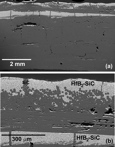
The location of the HfB2-SiC coating and the HfB2-loaded top layer was near the surface of the plate (). The HfB2 was the light phase in the secondary electron image. The HfB2 coating was not continuous, having cracked during the first pyrolysis of the composite; the cracks were subsequently infiltrated with neat SMP-10 during the re-infiltration cycles. It should be noted that at the 1300°C pyrolysis temperature, polymer-derived SiC that formed at the surface was expected to be nano-crystalline and compositionally close to SiC; however, a polymer-derived SiC typically contains some carbon and oxygen impurities [Citation24,Citation25]. For the remainder of the discussion, the derived ceramic will be referred to as SiC for simplicity.
Figure 1. (a) Overview of the as processed SiC/SiC-HfB2 composite. (b) Magnified image of the surface showing the HfB2-SiC and SiC phases in the matrix.
shows the surface temperatures measured during the tests along with optical images of the samples post-test. The initial temperature rise was captured, a quasi-steady state condition was achieved and the radiative cooling phase occurred after plasma shutdown. The maximum temperature achieved for Disk I was nominally 1600°C. The two pyrometers were observed to track with each other. Assuming an emissivity of 0.85 (with the strong hypothesis that global emissivity was equal to spectral emissivity at 1 µm) as reported in , the radiative equilibrium heat flux was 0.59 MW m−2 corresponding to a cold wall heat flux of 0.79 MW m−2 in line with the observation that metallic diborides exhibit very low catalytic behaviour [Citation23,Citation26,Citation27]. There was minimal oxidation of the sample surface (Disk I, inset). Disk II () was tested at a slightly lower heat flux than Disk I, but the hold time was increased from 137 to 395 s. At the start of the hold, the two pyrometer readings were similar, but above 1500°C, at about 150 s after sample insertion, a departure of the temperature readings was observed. The difference in the readings increased until the plasma shut-off. The surface of the sample was whiter, indicating increased oxidation compared to Disk I, likely due to the longer exposure time. A section of the oxide scale near the lower right edge of Disk II was lost during the removal of the sample from the sample holder; the remaining oxide scale was adherent. Crack like features in the scale were apparent on the surface of Disk II (); however, it will be shown in the cross-sectional SEM analysis that these regions correspond to inhomogeneous SiC regions that were present in the as processed sample, an effect of volume shrinkage during pre-ceramic polymer pyrolysis, rather than a result of phase changes of SiO2 or HfO2 in the oxide scale or CTE mismatch between oxide scale and substrate.
Figure 2. Temperature versus time plot for the four tested samples. The solid lines are the P800 pyrometer and the dotted lines of the corresponding color are the M1000 pyrometer readings. The locations marked SC are where the P800 was switched form dual-colour to single-color mode. The inset images show the surface of the samples after arc jet exposure for each disk.
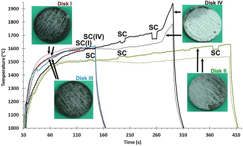
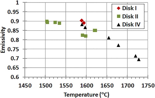
Figure 3. Calculated spectral emissivity at about 1 µm for the considered angle of view (60°) versus temperature measured for Disk I, Disk II and Disk IV. No measurements were taken on Disk III.
Disk III was exposed exactly at the same heat fluxes and duration as Disk I and, in fact, the temperature versus time profile and resulting oxide scale of Disk III was visually similar to that of Disk I. Disk IV () was exposed to an intermediate heat flux level but for longer duration than Disks I and III. Around 1600°C, at the 150 s mark, the pyrometers began reading different temperatures, as was the case for Disk II. Around the 260 s mark (1740°C), a dramatic rise in heating rate was observed for Disk IV. In fact, Disks I, Disk III and Disk IV all reached 1600°C after 150 s exposure, but the longer exposure of Disk IV caused incipient oxidation with emissivity reduction and a temperature that increased up to where the passive to active oxidation transition of SiC can occur.
For the samples with thicker oxide scales (Disk II and IV), the pyrometers readings diverged. The lighter colour of the oxide would induce a decrease in emissivity which may account for the difference in the pyrometer readings. Operating the pyrometers in DC mode should negate the impact of an emissivity change; however, this is based on the assumption that the emissivity of the material was the same at the different wavelengths detected by the pyrometer. The fact that the P800 and M1000 pyrometers use different wavelengths may explain the difference in temperature readings for Disk II and IV, potentially revealing the onset of significant low emissivity HfO2 formation. The locations marked SC in the temperature versus time plot () are where the P800 pyrometer was switched from dual-color to single-color mode and back for spectral emissivity evaluation. The calculation of emissivity from a comparison of single-color and dual-color modes was described by Monteverde et al. [Citation26]. The experimental value of emissivity obtained in this way () was the spectral emissivity value at the pyrometer single-color mode wavelength of 0.7 µm for the P800 angle of view. It was found that Disk I had a calculated emissivity value between 0.85 and 0.90 when measured between 1550 and 1600°C which is consistent with literature values for MeB2-SiC [Citation27]. Disk II initially started off with a similar calculated emissivity value between 1500 and 1550°C, but with rising temperature fell to around 0.80. This was expected, where in the insets in , the surface of Disk II was shown to be lighter in colour than that of Disk I, due to the formation of a continuous HfO2-SiO2 film, where even a thin MeO2 film can lower the emissivity [Citation28,Citation29]. Disk IV also begins with an emissivity between 0.85 and 0.90 at 1600°C, but then rapidly falls off with temperature for an emissivity of near 0.75 calculated around 1750°C. For comparison, emissivity values were measured at nominally the same temperature (∼1590°C) for Disks I, II and IV. The average of the values for Disk I, Disk II and Disk IV was 0.90, 0.82 and 0.87 respectively. The lower value for Disk II would indicate that even though the samples were at the same temperature, Disk II had been at the test conditions a longer time (∼200 s versus ∼120 s), and Disk II had more oxide coverage than Disks I and IV when emissivity was measured. As observed for Disk IV, increased oxidation of the HfB2 to HfO2 led to decreased emissivity; the lower emissivity caused surface temperatures to rise, due to an inability to reject heat by radiation. Furthermore, the oxide scale is expected to be less thermally conductive than HfB2-SiC CMC, which would limit heat transfer through conduction to cooler regions of the sample and into the sample holder and thus surface temperature was increased. At high enough temperatures (above 1600°C), removal of SiO2 by ablation due to its low viscosity also lowers emissivity and contributes to the escalating temperature rise seen in .
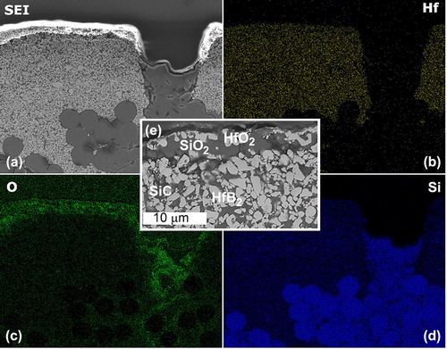
Examples of the oxide scales in Disk II and Disk III are shown in . The outer oxidation layer consisted of HfO2-SiO2 covering the HfB2-SiC coating, and SiO2 covering the SiC-rich regions in the coating. The phases were confirmed by EDS and visualised by a composition map. The composition maps ((a–d)) for Disk II are shown as an example while the micrograph ((e)) of the oxide scale is from Disk III. Disks I, II and III had similar morphologies and scale thicknesses. In Disk II, the sample exposed for the longest time, oxidation of the SiC-rich region that was created by the shrinkage cracks of the initial processing and subsequent re-infiltrations, led to oxygen penetration to the fibres embedded in this region that had lost defined edges; a sign of oxidation damage. Fibres embedded in the HfB2-SiC coating appeared unaffected.
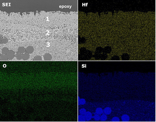
Figure 4. (a) Secondary electron image of the surface of Disk II after arc jet exposure. From the EDS maps for (b) Hf, (c) O and (d) Si, it is shown that there is a thin SiO2-HfO2 layer at the surface which is shown for Disk III in (e). The oxide scale is less than 10 µm and consists of SiO2 (dark phase) and HfO2 (light phase).
The oxidation scale in Disk IV () was comprised of a layered structure across the surface of the sample. The outermost layer (Layer 1) was comprised of either porous HfO2 or of HfO2 with SiO2 within the pores depending on the location in the sample. Loss of SiO2 at the surface could be due to ablation of the low viscosity SiO2 flow from the high gas flow of the arc jet, or direct formation of SiO and CO2 gases from SiC [Citation12]. Since SiO2 has a lower catalytic recombination efficiency compared to MeB2, removal of SiO2 can increase surface temperature through enhanced recombination reaction rates [Citation7,Citation27,Citation30,Citation31]. Layer 2 is a SiC-depleted layer of HfB2, and Layer 3 is the underlying, non-oxidised HfB2-SiC coating and matrix. Due to the open pathway created by the active oxidation of SiC, the interior of the CMC was impacted by the arc jet exposure. Loss of fibres and SiC matrix material was noted, along with oxygen ingress () underneath regions formerly filled with SiC. The fibres in Layer 3 (HfB2-SiC), beneath the oxide scale (Layers 1 and 2), were protected by the coating. The layered structure was similar to results seen in arc jet testing of hot pressed, bulk, HfB2-SiC samples, where temperatures exceeded the SiC passive to active oxidation transition [Citation12]. The increased mass loss due to SiC active oxidation was confirmed by weighing the samples before and after testing. The mass loss for Disk IV after arc jet exposure was 5.9% (89 mg), compared to only 0.04%, 1.5% and 0.6% mass losses for Disks I, Disk II and Disk III, respectively.
Figure 5. (a) Overview of the oxide scale formed on Disk IV after arc jet exposure. The oxide scale forms three distinct layers 1: porous HfO2; 2: SiC-depleted HfB2 and 3: HfB2-SiC. (b) Surface of the oxide scale. (c) Magnified image of the three layers. SiO2 is not found at the surface in (a), but can be found in some instances as shown in (d).
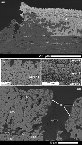
Figure 6. EDS map showing the removal of SiO2 in the outer layer and depletion of SiC from layer 2. Oxygen signal is associated with HfO2.
Comparing Disk III and Disk IV illustrates the impact of time and slow temperature increases on the transition to active oxidation. Although Disk IV was exposed to a lower heat flux, its longer exposure time allowed for a sufficient length of time for the sample to experience a jump in temperature rise rate. This temperature increase and its rate can be influenced by many factors including; emissivity change due to oxidation, surface catalytic efficiency and a decrease in sample surface thermal conductivity. However, it was noted that the fibres and matrix protected by the HfB2-SiC coating did not show signs of oxidation or any damage from the arc jet exposure. This suggested that if a continuous coating were to be applied by a modified processing method, the composite would experience minimum oxidation damage from the ∼1900°C exposure.
Summary
SiC/SiC-HfB2 CMC plates were prepared with an HfB2-SiC coating. Flat disks of the CMC were exposed to arc jet testing at different specific total enthalpies, from 14 to 17 MJ kg−1 and at pressures near 3000 Pa. Oxidation of the sample surface was dependent on the total enthalpy; however, the time of exposure also played a significant role. Maximum surface temperatures were recorded between 1600 and 1940°C. It was noted that factors such as the changing sample emissivity, due to oxidation of HfB2 and loss of SiO2 from the surface, coupled with the active oxidation of SiC and changes in the catalytic efficiency of the surface led to different temperature readings and impacted the material response. The HfB2-SiC coating proved to be effective at protecting the underlying composite up to the highest surface temperatures investigated. However, an oxygen ingress path resulted from SiC-rich regions in the coating that were formed during sample fabrication. A refinement of the coating process to fill voids left after the initial coating application with HfB2-SiC should improve the oxidation resistance of similar CMCs.
Acknowledgements
This paper was originally presented at the Ultra-High Temperature Ceramics: Materials for Extreme Environments Applications IV Conference (Windsor, UK) and has subsequently been revised and extended before consideration by Advances in Applied Ceramics.
Disclosure statement
No potential conflict of interest was reported by the authors.
ORCID
D. King http://orcid.org/0000-0001-7967-9199
T. Parthasarathy http://orcid.org/0000-0001-7492-0668
Additional information
Funding
References
- Yang X, Zhao-hui C, Feng C. High-temperature protective coatings for C/SiC composites. J Asian Ceram Soc. 2014;2(4):305–309. doi: 10.1016/j.jascer.2014.07.004
- Krenkel W, Berndt F. C/C–SiC composites for space applications and advanced friction systems. Mater Sci Eng A. 2005;412(1):177–181. doi: 10.1016/j.msea.2005.08.204
- Zhu YC, Ohtani S, Sato Y, et al. The improvement in oxidation resistance of CVD-SiC coated C/C composites by silicon infiltration pretreatment. Carbon N Y. 1998;36(7):929–935. doi: 10.1016/S0008-6223(97)00207-8
- Jian-Feng H, Miao L, Wang B, et al. SiCf/SiC oxidation protective coating for carbon/carbon composites. Carbon N Y. 2009;47(4):1198–1201. doi: 10.1016/j.carbon.2009.01.002
- Bill J, Heimann D. Polymer-derived ceramic coatings on C/C-SiC composites. J Eur Ceram Soc. 1996;16(10):1115–1120. doi: 10.1016/0955-2219(96)00025-8
- Paul A, Rubio V, Binner J, et al. Evaluation of the high temperature performance of HfB2 UHTC particulate filled Cf/C composites. Int J App Ceram Tech. 2017;14(3):344–353. doi: 10.1111/ijac.12659
- Alfano D, Scatteia L, Monteverde F, et al. Microstructural characterization of ZrB2–SiC based UHTC tested in the MESOX plasma facility. J Euro Ceram Soc. 2010;30(11):2345–2355. doi: 10.1016/j.jeurceramsoc.2010.02.013
- Tang S, Deng J, Wang S, et al. Ablation behaviors of ultra-high temperature ceramic composites. Mater Sci Eng A. 2007;465(1):1–7. doi: 10.1016/j.msea.2007.02.040
- Xie J, Li K, Li H, et al. Ablation behavior and mechanism of C/C–ZrC–SiC composites under an oxyacetylene torch at 3000°C. Ceram Inter. 2013;39(4):4171–4178. doi: 10.1016/j.ceramint.2012.10.273
- Racek O, Berndt CC, Guru DN, et al. Nanostructured and conventional YSZ coatings deposited using APS and TTPR techniques. Surf Coat Tech. 2006;201(1):338–346. doi: 10.1016/j.surfcoat.2005.11.122
- Hald H. Operational limits for reusable space transportation systems due to physical boundaries of C/SiC materials. Aerospace Sci Tech. 2003;7(7):551–559. doi: 10.1016/S1270-9638(03)00054-3
- Gasch M, Ellerby DT, Johnson SM. Processing, properties and arc jet oxidation of hafnium diboride/silicon carbide ultra high temperature ceramics. J Mater Sci. 2004;39(19):5925–5937. doi: 10.1023/B:JMSC.0000041689.90456.af
- Jacobson NS, Myers DL. Active oxidation of SiC. Oxid Met. 2011;75(1):1–25. doi: 10.1007/s11085-010-9216-4
- Wuchina E, Opila E, Opeka M, et al. UHTCs: ultra-high temperature ceramic materials for extreme environment applications. Electrochem Soc Interface. 2007;16(4):30.
- Lu W, Qian-gang F, Feng-ling Z. A novel gradient SiC-ZrB2-MoSi2 coating for SiC coated C/C composites by supersonic plasma spraying. Surf Coat Technol. 2017;313:63–72. doi: 10.1016/j.surfcoat.2017.01.019
- Carney C, Leslie C, Jones E. Oxidation of SiCf/SiC-HfB2 composites under laser heating. Inter J App Ceram Technol. 2016;13(2):295–301. doi: 10.1111/ijac.12453
- King D, Zlatomir A, Key T, et al. Novel processing approach to polymer-derived ceramic matrix composites. Inter J App Ceram Technol. 2018;15(2):399–408. doi: 10.1111/ijac.12805
- Carney C, Wilks G. Refractory coatings for ceramic matrix composites and associated methods. United States Patent Pending (2017).
- Krasnov NF. Aerodynamics of bodies of revolutions. New York (NY): American Elsevier, Publishing Company; 1970.
- Purpura CF, De Filippis E, Graps E, et al. The GHIBLI plasma wind tunnel: description of the new CIRA-PWT facility. Acta Astronaut. 2007;61:331–340. doi: 10.1016/j.actaastro.2007.01.046
- Caristia S, De Filippis F, Del Vecchio A, et al. Scirocco PWT facility for high temperature material assembly testing. Paper presented at: 54th IAC; 2003; Bremen.
- Savino R, De Stefano Fumo M, Silvestroni L, et al. Arc jet testing on HfB2 and HfC-based ultra-high temperature ceramic materials. J. Euro Ceram Soc. 2008;28(9):1899-1907. doi: 10.1016/j.jeurceramsoc.2007.11.021
- Zoby VE. Empirical Stagnation Point Heat Transfer Relation in Several Gas Mixtures at High Enthalpy Levels. NASA TN – D4799, Washington (DC), 1968 October.
- Bouillon E, Langlais F, Pailler R, et al. Conversion mechanisms of a polycarbosilane precursor into an SiC-based ceramic material. J. Mater. Sci. 1991;26(5):1333–1345. doi: 10.1007/BF00544474
- Ly HQ, Taylor R, Day RJ, et al. Conversion of polycarbosilane (PCS) to SiC-based ceramic part 1. Characterisation of PCS and curing products. J Mater Sci. 2001;36(16):4037–4043. doi: 10.1023/A:1017942826657
- Monteverde F, Savino R, De Stefano Fumo M, et al. Plasma wind tunnel testing of ultra-high temperature ZrB2–SiC composites under hypersonic re-entry conditions. J Euro Ceram Soc. 2010;30(11):2313–2321. doi: 10.1016/j.jeurceramsoc.2010.01.029
- Scatteia L, Alfano D, Monteverde F, et al. Effect of the machining method on the catalycity and emissivity of ZrB2 and ZrB2–HfB2-based ceramics. J Amer Ceram Soc. 2008;91(5):1461–1468. doi: 10.1111/j.1551-2916.2008.02325.x
- Chekhovskoi VY, Tarasov VD, Grigor'eva N. The spectral emissivity of an oxide film of zirconium for wavelengths of 530 and 650 nm in the temperature range from 1450 to 1750K. High Temp. 2004;42(2):252–258. doi: 10.1023/B:HITE.0000026157.04515.18
- Ohlhorst C, Vaughn WL, Lewis RK, et al. Arc jet results on candidate high temperature coatings for NASA’s NGLT refractory composite leading edge task. Place: NASA Langley; 2003. (NASA Technical Reports Server; 20040040337).
- Savino R, De Stefano Fumo M, Paterna D, et al. Arc jet testing of ultra-high-temperature-ceramics. Aerospace Sci Tech. 2010;14(3):178–187. doi: 10.1016/j.ast.2009.12.004
- Alfano D, Scatteia L, Cantoni S, et al. Emissivity and catalycity measurements on SiC-coated carbon fibre reinforced silicon carbide composite. J Euro Ceram Soc. 2009;29(10):2045–2205. doi: 10.1016/j.jeurceramsoc.2008.12.011