
 ?Mathematical formulae have been encoded as MathML and are displayed in this HTML version using MathJax in order to improve their display. Uncheck the box to turn MathJax off. This feature requires Javascript. Click on a formula to zoom.
ABSTRACT
Welded metallic structures are usually prone to different forms of degradation in the mechanical properties during their life span such as fatigue. Tungsten Inert Gas remelting is a post-weld treatment method which gained increasing interest in the last decades. However, more light should be thrown on the behavior of the existing cracked structures retrofitted by TIG-remelting. Therefore, fatigue test results of several welded details improved TIG-remelting have been extracted. Around 130 test results with different existing crack sizes are presented and analyzed. The gain factor in fatigue is defined and calculated for the collected data. TIG-remelting shows high potential in life extension. In fact, TIG-remelting is found to give a fair life extension greater than the design life of the new details even when 2 crack mm remains. Besides, toe radius and residual stresses are found to vary significantly after TIG-remelting depending on the remelting parameters and the steel type.
1. Introduction
Welding is by far the most used method for joining and assembling steel structures. Nonetheless, fatigue appears to be one of the challenges that endanger the durability of such structures. Fatigue cracks usually start from the weld toes when the structure is subjected to repetitive loading because of several reasons. The tensile welding residual stresses which usually dominates at the weld toe is one of these reasons. Other reasons for weld toe cracking are the welding induced defects and the high-stress concentration at the weld toe. All the aforementioned factors limit the fatigue life of the structure. Therefore, the fatigue limit state (FLS) is to be taken into account when designing or assessing steel structures.
| Nomenclature | ||
| a | = | crack depth |
| ar | = | remaining crack depth after TIG remelting |
| df | = | depth of fusion |
| NEXT | = | fatigue life of the repaired specimen by TIG-remelting |
| NIIW | = | design life of the repaired specimen according to the recommendation |
| NAW | = | mean as-welded fatigue life |
| Npre | = | applied number of cycles before treatment |
| G | = | gain factor in fatigue life |
| IIW | = | international institute of welding |
| fy | = | yield strength |
| R | = | stress ratio |
Several post-weld treatment methods were proposed to extend the fatigue life of existing structures. Some of them rely on improving the weld toe radius to reduce local stresses at the weld toe. This is usually done by remelting the area in the weld toe’s vicinity. Moreover, remelting removes any small surface crack that appears due to fatigue loading during the service life (i.e. Pre-fatigue loading). Tungsten electrodes are of high efficiency because of their high melting temperature and durability. Moreover, on contrary to manual arc welding, TIG electrode is quite focused and affects only the weld toe’s vicinity.
Tungsten Inert Gas remelting (TIG-remelting) can be used for both enhancing the fatigue strength of new structures or extending the fatigue life of existing structures (Al-Karawi Citation2020). Several research studies established the benefits of TIG-remelting in enhancing the strength of new structures (Haagensen Citation1979). Moreover, the effect of crack size on the efficiency of TIG remelting was studied for cover plate details (Fisher et al. Citation1978), transverse attachments (Ramalho et al. Citation2011) and longitudinal attachments (Miki et al. Citation1987). The common conclusion in all these research articles is the dependency of the efficiency on the crack size before treatment and the fusion depth.
The use of TIG-remelting in life extension and crack repair has gained increasing interest among engineers and researchers in the field. Nonetheless, there is a need for providing a firm conclusion about the efficiency of this method in extending the life of existing structures that may contain cracks. Therefore, more than 130 fatigue test results with different stress ratios, plate thicknesses and steel types are collected and analyzed. The studied specimens contain cracks of different sizes. This manuscript contributes to investigate the efficiency of TIG-remelting in extending the fatigue life of existing details and retrofit cracks in their weld toes. Moreover, a light is thrown on the local geometry and material changes at the weld toe after TIG-remelting.
2. Method
Fatigue test results of repaired welded structures by TIG-remelting are collected from several research articles. The extracted results are either tabulated or presented in fatigue strength curves (S-N curves) in the source papers. The data are divided into two groups depending on the availability of crack size after remelting. In some cases, cracks are completely removed after remelting and this is confirmed by either crack detection or metallurgical investigation. Information about the extracted data points together with the references are given in . The distributions of the extracted fatigue test results with respect to detail type and yield strength are shown in .
Figure 1. The distribution of the collected data with respect to detail type and yield strength.
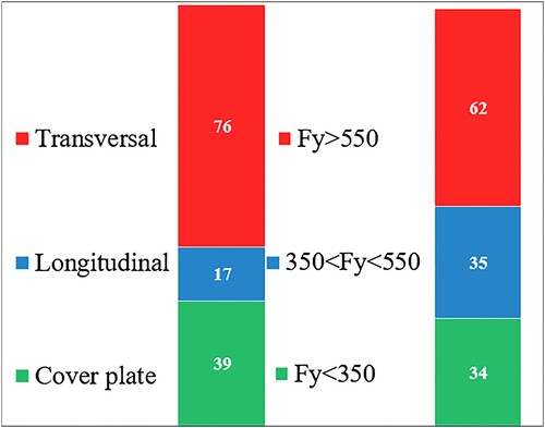
Table 1. The collected experimental fatigue data for prefatigued joints improved by TIG-remelting.
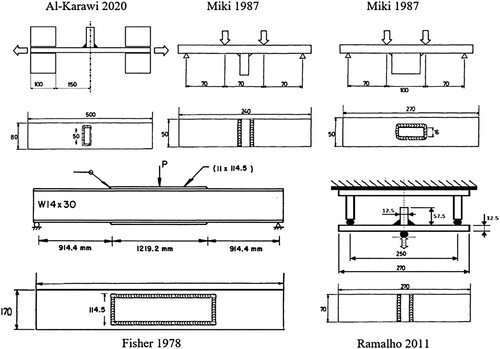
The transverse attachments used in (Al-Karawi Citation2020) are made of S355 structural steel, and the filler material is made of C6LF. The specimens are subjected to axial pulsating loading with a stress ratio R = 0.29. The test specimens in this series contain 0.6–1.2 mm crack before TIG-remelting. The cracks are inspected via several strain gauges placed 1–2 mm from the weld toe. Different stress ranges are applied starting from 150 to 250 MPa. The test performed in (Miki et al. Citation1987) is conducted under a stress ratio of 0.1, and stress ranges from 275 to 456 MPa. The steel used to manufacture the test specimens are SM58 steel (fy = 590 MPa), and SM50 steel (fy = 410 MPa). The specimens contain cracks of different sizes up to 7.5 mm deep. The crack length and depth are detected by dye penetrant and ultrasonic testing respectively. The remelting parameters are selected so the fusion depth reaches 3–4 mm.
The cover plate details used in (Fisher et al. Citation1978) are tested under different stress ratios and different stress ranges from 82 to 165 MPa. The tests are terminated when a visible crack appears at the surface or when 75% of the expected fatigue life is reached. Three-point alternating bending is applied to the specimens to generate the cracks. The cover plate and the girder are made of A36 which has a relatively low yield strength of 252 MPa. Both TIG and plasma electrodes are used in (Ramalho et al. Citation2011) to treat weld toe of transverse attachments. The plasma dressing is used because of its capability to repair deeper cracks. Three-point alternating bending is applied to generate cracks (3–5 mm deep), when the crack reaches a specific depth the test is terminated, and the specimens are then treated by either TIG or plasma arcs, and then tested to failure. The test is conducted under a low R-ratio = 0.05, and the used steel has a yield strength = 384 MPa. The specimen’s geometry and test setup for all above-mentioned series are shown in .
Figure 2. The geometry of the specimens used in .
In order to quantify the efficiency of the treatment in fatigue life extension, a gain factor in fatigue life is introduced in Equation (1). This factor gives the ratio between the fatigue life of the specimen after remelting (i.e. obtained experimentally) to the design life of the enhanced specimen by TIG-remelting (i.e. obtained from the characteristic S-N curve (97.7% survival probability) of the TIG-treated detail according to the International Institute of Welding (IIW) recommendations (Haagensen and Maddox Citation1995)). In other words, if the gain factor is greater than 1.0, TIG-remelting can extend the fatigue life, so that new design life can be reached. Despite that the term ‘Gain factor’ is used before in some research articles (Leitner et al. Citation2016), however, relating it to the design life proposed by the IIW recommendations is a new of its kind.
(1)
(1)
In most cases, the specimens fail from their toes due to fatigue loading. Nonetheless, more than 10% of them fail from the weld root, and 5% of them fail from the clamping position in the base metal. These failure positions (i.e. root and clamping failures) indicates the significant strength at the weld toe after TIG-remelting which causes the failure to start from other strong positions (weld root or base metal). Moreover, more than 15% of the studied specimens do not fail even after many million cycles of loading (i.e. more than 5 million cycles). This also indicates the strength of the weld toe after remelting. These specimens were referred in this article as ‘Runout specimens’.
3. Results
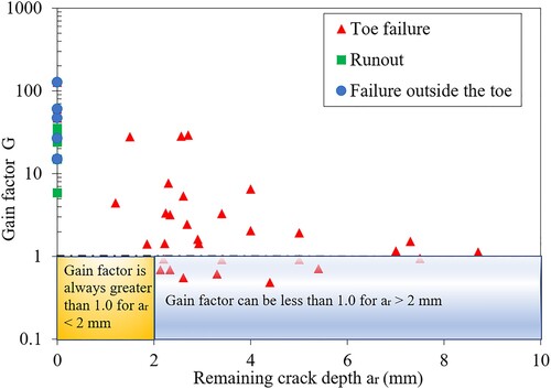
The dependency of the treatment efficiency on the remaining crack size after remelting is shown in . The figure shows that when the crack is completely removed (i.e. No remaining crack, ar = 0), the gain factor would be significantly larger than 1.0. Moreover, the specimens – in case of full crack removal – never show toe failure as indicated in the figure (i.e. they either runout or fail outside the weld toe). This implies that the obtained gain factors are on the safe side. In fact, a gain factor greater than 1.0 can be achieved even when the remaining crack size is up to 2 mm as shown in the figure. It is mention-worthy that only the data point at which the remaining crack size is known are plotted in this figure.
Figure 3. The gain factor in fatigue life versus the remaining crack size.
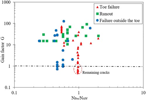
Another way of studying the capability of TIG-remelting in fatigue life extension is to plot the gain factor against the applied number of cycles before treatment NPre as shown in . The number of cycles before treatment NPre is normalized to the mean fatigue life of the as-welded specimens NAW . This normalisation is important to consider the difference in stress ranges and detail types for each data point. When this ratio (NPre /NAW) is equal to 1.0, this means that the structure is subjected to a number of cycles that equal to the mean as-welded fatigue life. The mean fatigue life is obtained experimentally from the S-N curves of the as-welded details found in the same articles. The figure indicates that even when the details are pre-fatigued to its as-welded fatigue life before remelting, gain factors greater than 1.0 can be reached providing that there is no remaining crack.
Figure 4. The gain factor in fatigue life versus the percentage of prefatigued loading to the design life.
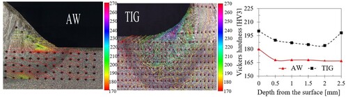
and show that the results are highly scattered as the gain factors vary from less than 1 to more than 100. In addition to the scatter in the remaining crack sizes and the number of cycles before treatment, the scatter may also be attributed to the difference in the obtained microstructure after treatment. In some cases, TIG-remelting causes an increase in hardness after treatment (Al-Karawi Citation2020) as shown in . While in other cases, strain-softening would have resulted after treatment in the heat-affected zone (Van Es et al. Citation2013).
Figure 5. Hardness increase at the weld toe vicinity due to TIG remelting (Al-Karawi Citation2020).
Another factor that might be decisive is the status of residual stresses at the weld toe after treatment which can be either tensile or compressive. The magnitude of the residual stress depends on many factors such as the remelting parameters, the detail’s geometry, the residual stress status before remelting and the type of steel. shows that compressive residual stress dominates at the weld toe after TIG-remelting in most of the cases. The given residual stresses in the table are either measured by a specific measurement method or obtained by elastic-plastic finite element simulation.
Table 2. Surface residual stress before and after TIG-remelting.
The degree of geometry improvement varies from one case to another depending on the remelting parameters. Moreover, if the original radius is relatively small, the improvement in weld toe radius would be extremely gainful. On the other hand, if the toe radius is already large (e.g. which is the case for vertical welding), the increase in toe radius by TIG-remelting would be less gainful (Ramalho et al. Citation2011). Besides, the standard deviation increases after TIG-remelting in comparison to the as-welded state. See which gives the toe radius values (i.e. mean and standard deviation) measured for different types of welded details.
Table 3. Weld toe radius before and after TIG remelting.
All the above-mentioned factors (geometry improvement, residual stress change, microstructural changes) shall always be included when fatigue life assessment is to be conducted. Nonetheless, the variation of these factors (residual stresses, geometry and hardness) only alters the degree of improvement, but fatigue life extension with a gain factor G > 1.0 would be always the case providing there is no remaining cracks larger than 2 mm as shown in and .
4. Discussion
shows that the efficiency of the treatment is dependent on the remaining crack size. This implies that an accurate crack detection method is required to quantify the crack size. The used inspection method should have the capability of detecting a 2 mm deep crack or less. Ultrasonic testing – for example – has the capability of detecting surface or sub-surface cracks smaller than 2 mm with a high probability of crack detection (Al-Karawi Citation2020). Since ultrasonic testing is relatively expensive, dye penetrant can be used to check if there is a crack at the surface. If no crack is found, TIG-remelting can be used, and new fatigue life (NIIW) can be claimed. Otherwise, another cracked detection method is needed to inspect the crack depth (e.g. ultrasonic testing).
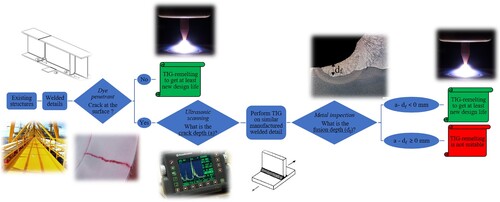
If dye penetrant reveals a surface crack, metallographic analysis on similar manufactured detail is suggested to check the possibility of obtaining fusion depth greater than the existing crack depth measured by ultrasonic testing. The depth of the fusion is of great importance since no crack removal is guaranteed elsewhere (i.e. in the heat-affected zone) as shown in . Besides, if the crack size is significantly larger than the fusion depth, TIG-remelting is not recommended to repair the welded details. The flowchart shown in summarizes the process of life extension of existing structures by TIG-remelting.
Figure 6. Remaining crack in the heat-affected zone and the base metal after TIG remelting.
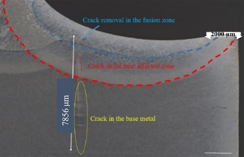
Figure 7. Flowchart of the fatigue life extension process using TIG-remelting.
shows that the existence of up to 2 mm deep crack after remelting does not affect the life extension, as the resulted gain factor is greater than 1.0. However, there are inherent uncertainties in any inspection method (including ultrasonic testing) used to estimate the crack depth. This means that the actual crack depth can be greater than the estimated value. Therefore, if 2 mm crack is allowed after remelting, the actual crack size could be greater, and the efficiency of TIG-remelting could decrease. Therefore, the remelting should aim at removing the crack completely (a-df <0 mm) as shown in .
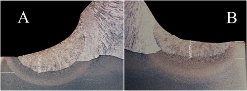
When TIG-remelting is to be applied on an existing structure -which may contain cracks-, the electrode should be positioned right at the weld toe where the crack exists. This practice does not comply with IIW recommendations for treating new welded structure (Haagensen and Maddox Citation1995), which suggested fitting the electrode 1–2 mm off the weld toe to provide a smoother transition and avoid the risk of new undercut formation. However, for existing structures, crack removal should be prioritized over geometry optimisation. Nonetheless, the toe radius should have a minimum value greater than 3 mm according to the IIW recommendations (Haagensen and Maddox Citation1995). See which shows the two cases: A for the deeper fusion with a less smooth transition, and B for a smoother transition but shallower fusion depth.
Figure 8. Influence of the position of the TIG-electrode on the smoothness and the depth of fusion.
5. Conclusions
This paper presents an analysis of the efficiency of TIG-remelting in fatigue life extension of existing structures. More than 130 data points obtained from fatigue tests are collected and analyzed using the introduced gain factor. TIG-remelting is found to give a significant fatigue life extension even when the fatigue life of the studied detail has been reached, providing that the remaining crack size after remelting is smaller than 2 mm. In fact, new design fatigue life of the TIG-treated detail can be claimed if this condition is fulfilled. Therefore, crack detection is needed beforehand to ensure the capability of crack fusion after remelting. Two parameters influence the degree of improvement: the depth of fusion and the radius of the weld toe when treating existing cracked structures. Besides, TIG-electrode should be placed right at the weld toe to get the largest possible fusion depth, and a minimum weld toe radius should be larger than 3 mm. Moreover, residual stresses and toe radii are found to be widely scattered after TIG-remelting but are always beneficial and contribute to fatigue life extension.
Acknowledgements
The author is grateful to the road administration Trafikverket and the innovation system agency in Sweden Vinnova (InfraSweden 2030) who financed the whole research project.
Disclosure statement
No potential conflict of interest was reported by the author(s).
Additional information
Funding
References
- Al-Karawi H. 2020. RU franz von Bock und Polach, and Mohammad Al-Emrani. ‘Fatigue crack repair in welded structures via tungsten inert gas remelting and high frequency mechanical impact’. J Constr Steel Res. 172:106200.
- Al-Karawi HA. 2021. Fatigue life estimation of welded structures enhanced by combined thermo-mechanical treatment methods. J Constr Steel Res. 187:106961.
- Anami K, et al. 2000. Improving fatigue strength of welded joints by hammer peening and TIG-dressing. Doboku Gakkai Ronbunshu. 2000(647):67–78.
- Ferro P, et al. 2019. Numerical modelling of residual stress redistribution induced by TIG-dressing: TIG-dressing numerical modelling. Frattura ed Integrità Strutturale. 13(47):221–230.
- Ferro P, Berto F, James MN. 2017. A simplified model for TIG-dressing numerical simulation. Modell Simul Mater Sci Eng. 25(3):035012.
- Fisher JW, et al. 1978. Retrofitting fatigue damaged bridges. Transp Res Rec 664.
- Fisher JW, Hausammann H, Pense AW. 1979. Retrofitting procedures for fatigue damaged full-scale welded bridge beams, Final Report, January 1979.
- Haagensen PJ. 1979. TIG dressing of steel weldments for improved fatigue performance. Offshore Technologies Conference.
- Haagensen PJ, Maddox SJ. 1995. IIW recommendations on post weld improvement of steel and aluminum structures. IIW Doc. XIII-2200r1-07, 2008. TIG dressing. Collaborative Test Program on Improvement techniques.
- Leitner M, Barsoum Z, Schäfers F. 2016. Crack propagation analysis and rehabilitation by HFMI of pre-fatigued welded structures. Weld World. 60(3):581–592.
- Lieurade HP, Huther I, Lefebvre F. 2008. Effect of weld quality and postweld improvement techniques on the fatigue resistance of extra high strength steels. Weld World. 52(7):106–115.
- Martinez LL, et al. 1997. Investigation of residual stresses in as-welded and TIG-dressed specimens subjected to static/spectrum loading. NESCO: Welded High-Strength Steel Structures, Stockholm.
- Miki C, et al. 1987. Retrofitting fatigue-cracked joints by TIG arc remelting. Doboku Gakkai Ronbunshu. 1987(380):111–119.
- Miki C, et al. 1989. Repair of fatigue damage in cross bracing connections in steel girder bridges. Doboku Gakkai Ronbunshu. 1989(404):53–61.
- Ramalho AL, Ferreira JA, Branco CA. 2011. Fatigue behavior of T welded joints rehabilitated by tungsten inert gas and plasma dressing. Mater Des. 32(10):4705–4713.
- Van Es SH, Kolstein MH, Pijpers RJM, Bijlaard FSK. 2013. TIG-dressing of high strength steel butt welded connections – Part 1: weld toe geometry and local hardness. Procedia Eng. 66:216–225.