
 ?Mathematical formulae have been encoded as MathML and are displayed in this HTML version using MathJax in order to improve their display. Uncheck the box to turn MathJax off. This feature requires Javascript. Click on a formula to zoom.
ABSTRACT
This paper presents a literature review of analytical, numerical, and experimental methods for evaluating the structural response of Offshore Wind Turbines (OWT's) during ship collision events. The different energy transfer mechanisms involved throughout a collision against fixed or floating OWT substructures are examined, whilst documenting some of the most common procedures in the assessment of wind load effects, soil–structure interaction, mooring lines contribution and hydrodynamic coupling. A survey of internal mechanics and external dynamics approaches developed for ship-structures collision events is carried out with a discussion on their potential application in analyses involving different types of substructures. Moreover, different hydrodynamic coupling schemes found in the literature are studied, highlighting the importance of hydro-effects in the collision analysis. Common practices in the use of metallic and cementitious material constitutive models in ship-collision analysis are also presented, whereas the structural behaviour of reinforced concrete structures submitted to impact loads, which has been rarely studied outside high-velocity impact/blast applications, is discussed in the current context. Finally, some of the most important limitations of the analytical and numerical models used in ship-OWT collisions are identified, from which suggestions are provided for future research endeavors.
1. Introduction
Over the last years, offshore wind has gained significant momentum with the increasing efforts to decarbonise global energy production. According to the International Energy Agency (IEA) in a 2020 report (IEA Citation2020), the offshore wind market grew nearly 30 per year between 2010 and 2018, faster than any other electricity source with the exception of solar photo-voltaic. Decreasing costs driven by technological developments enabled a rapid expansion in the number of deployed and planned offshore wind installations, especially in Europe and China. Aside from typical shallow water coastal wind farms, developers are also looking into deeper waters further away from the shore. These areas present great untapped potential which has become viable more recently thanks to new wind turbine concepts based on floating foundations (such as spar, barge and tension-leg platforms), technologies adapted from the oil and gas industry. Prospects are positive and the offshore wind industry is set to continue gaining more space, with 150 new projects across 19 countries scheduled to be completed by 2021, according to IEA's report.
In this context, with the increasing number of offshore wind installations, often located near maritime traffic lanes, collision events with drifting ships and approaching service vessels become more likely, raising safety concerns for regulatory agencies and project stakeholders. For this reason, an extensive risk assessment is generally performed in early design stages of a wind farm development. This procedure is aimed at building a thorough understanding of the collision risk and required mitigating measures. At the level of an individual wind turbine, in order to ensure the crashworthiness of the structure given a particular Accidental Limit State (ALS), structural analysts must rely on a range of different methodologies, usually based on either non-linear finite elements or simplified analytical formulations, to estimate resulting damage and residual strength.
Offshore wind has drawn significant engineering know-how from the long-standing oil and gas industry, not only in terms of structural design of wind turbine foundations and substructures, but also manufacturing, installation and maintenance procedures. Despite this, there are important particularities in offshore wind turbines that create the need for more focused research. For instance, tall and slender wind turbine towers with heavy masses located high up in the nacelle may present very different dynamic responses when compared to generally stiffer oil and gas platforms. Moreover, wind loads can have much more influence on the structural behaviour of wind turbines and especially in the case of floating turbines, where highly complex physical interactions between the wind and hydrodynamic effects might take place.
This article is divided into two main parts. First, the concept of accidental limit states applied to offshore wind turbines is briefly introduced, followed by a detailed description of physical processes that govern a collision between a vessel and an OWT, either fixed or floating. External dynamics, internal mechanics, coupling approaches, Soil–Structure Interactions (SSI), mooring physical mechanisms and wind effects are addressed. The second part is focused on methodologies for structural damage analysis found in the literature. It encompasses experimental, analytical and numerical methods. Additionally, an overview of modelling techniques for steel and concrete materials, external dynamics and internal mechanics coupling, SSI, mooring and wind loads is provided. To conclude, current methodologies and some proposals for future research on the subject of ship-OWT collisions are discussed.
2. Accidental limit state
A limit state is a condition for which a structure is designed in order to withstand a particular applied load. If a limit state is exceeded, the structure is considered no longer able to fulfil its intended function for that particular state. In ship and offshore structures design, four basic categories are defined for structural limit states: Ultimate Limit States (ULS), Serviceability Limit States (SLS), Fatigue Limit States (FLS) and Accidental Limit States (ALS).
Accidental Limit States refer to critical conditions resulting from accidental events such as fires, collisions, grounding and explosions. The design of a structure against accidental loads is aimed at avoiding catastrophic outcomes resulting in casualties, damage to the environment and economic losses. Typically, an ALS is defined based on two main criteria: the ability of the structure to withstand an accidental load, and its damaged performance when subjected to service loads after an accidental event. Consequences of a ship-OWT collision are normally required to be addressed in most classification societies for both ULS and ALS.
For example, in Floating Offshore Wind Turbine Structures Design Standards (DNV GL Citation2018), accidental loads for floating wind turbine structures shall be taken as having an annual probability of . Loads from collision with service vessels shall be considered, and two types of collision analyses are recommended: operational boat impacts, with a speed no less than 0.5 m/s and accidental boat impacts, with a minimum drifting speed of 2 m/s.
In the rules for the classification of offshore units NR445 (Bureau Veritas Citation2016), the damage likely to occur by the effect of collision shall be evaluated when required by the risk analysis. Two types of collisions are defined: minor collisions, where the vessel involved has a mass and dimensions small compared to the offshore unit; and major collisions, where the vessel dimensions are significant compared to the offshore unit.
For a supply vessel, Lloyd's Register (LRG Citation2014) makes a distinction between the different types of possible accidental collision scenarios: on arrival, waiting in standby position and during loading (manoeuvring and drifting). A calculation of the collision frequency and energy for each scenario is recommended.
A proper estimation of ship-OWT's collision frequencies is fundamental in risk evaluation frameworks. However, this parameter depends highly on factors that are generally comprised within the wind farm location, wind farm layout, and ship traffic characteristics, being inherent thus to the specific study case. Different methods can be used to estimate the collision frequency such as historical data using accidental databases, rational models, judgmental evaluation, event trees, Bayesian analysis, among others. Nonetheless, although the present research work is focused on reviewing the methodologies used in the analysis of ship collision's consequences, rather than its occurrences, the reader is referred to works regarding ship-OWT's collision risk assessment such as Dai et al. (Citation2013), Moan et al. (Citation2019), Zhang S et al. (Citation2019), Mujeeb-Ahmed and Paik (Citation2021) and Yu Q et al. (Citation2021).
3. Collision physics
From an energy dissipation perspective, although a ship collision event with an OWT presents some fundamental similarities to ship–ship collisions, different energy transfer mechanisms such as soil–structure interaction in the case of fixed structures, and hydrodynamic and mooring forces for floating turbines, need to be accounted for in the assessment of the structural response of the collided bodies, as illustrated in .
Figure 1. Ship impact against a fixed (left) and a floating wind turbine (right). (This figure is available in colour online.)
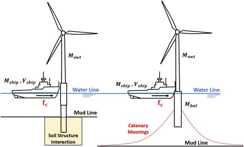
The most general formulation for the energy transferred in a collision between a ship and an OWT may be written as:
(1)
(1) where
denotes the initial kinetic energy of the impacting ship,
and
the structural internal energies (i.e. sum of elastic and plastic contributions) of the collided structures,
and
the kinetic energies after the collision event,
the energy dissipated through diffraction, radiation and viscous hydrodynamic forces,
the energy dissipated by the mooring system (i.e. sum of potential, kinetic and deformation energy in the case of a catenary moorings) and
the energy dissipated by pressure and friction in the soil–structure interface. Equation (Equation1
(1)
(1) ) is modified depending on the type of structure and the involved dissipation mechanisms (e.g.
for a floating structure,
for a fixed structure, and so on). Assessing each term of Equation (Equation1
(1)
(1) ) in a simple yet accurate manner becomes a priority for the analyst, especially when considering complex non-linear phenomena such as SSI effects or hydrodynamic couplings.
Typically, the collision dynamics in classical ship collision theory is divided into two processes: the External Dynamics and the Internal Mechanics. On one hand, the external dynamics deals with the rigid-body motions of the involved floating bodies during and after impact. It estimates how much of the initial kinetic energy of the system is dissipated by hydrodynamic forces such as water added mass, buoyancy, wave radiation and drag forces. The internal mechanics, on the other hand, describes how the initial kinetic energy is dissipated into different structural deformation and sliding (frictional) mechanisms.
Detailed discussions on external dynamics and internal mechanics of ship-OWT collisions are presented in Sections 3.1 and 3.2, respectively. As both processes are strongly coupled in the case of ship-FOWT collisions, Section 3.3 is devoted to the existing coupling approaches. Soil–Structure interaction, mooring dynamics and wind load effects are, respectively, treated in Sections 3.4, 3.5 and 3.6.
3.1. External dynamics
The external dynamics in ship collision analysis is concerned with the rigid-body motions of the structures during and after the collision event. The kinematics of the collided bodies can be found directly from derivations using the conservation of energy and momentum principles, or by assembling and solving the resulting Equation of Motion (EOM) derived from classical mechanics, taking into account the inertial, damping and restoring forces (discussed in detail in Section 3.3). The general formulation for the momentum conservation in a ship-OWT impact is given by:
(2)
(2) where
and
are the ship and OWT masses,
and
their corresponding added masses, and
,
their initial and final velocities, respectively.
Depending on the relative stiffness and mass of the collided structures, further assumptions can be done in Equation (Equation2(2)
(2) ), especially regarding their added mass coefficients, which are not constant and depend on the motion of the floating object. Nevertheless, in the case of collisions against offshore structures, it is often assumed that the natural period of the rigid body motion of the impacted structure is much larger than the duration of the collision event. Therefore, the external dynamics can be decoupled from the internal mechanics, which helps to further simplify the problem (Soreide and Amdahl Citation1983; Bai and Jin Citation2016). It is worth noting that methods based solely on external collision dynamic simplifications allow for closed-form solutions that can be very useful in early design stages, as they give a quick estimation of how the energy dissipates in rigid body motions of both structures for a given collision scenario. However, they usually do not take into account how the energy is being dissipated in each of its components, such as moorings elongation, soil stressing, and structural deformation.
3.2. Internal mechanics
Internal mechanics deals with the energy dissipation associated to the structural deformation of the collided bodies, that is and
in Equation (Equation1
(1)
(1) ). In classical ship collision theory, establishing relationships such as force-penetration curves for ship structural members using plastic analysis is quite common, as the energy absorbed by elastic deformation is often negligible compared to the plastic one. As a result, simple closed-form solutions that correspond well with experimental testing have been derived for different structural components, as shown for instance by Amdahl (Citation1983), Simonsen and Ocakli (Citation1999), Paik (Citation2018) or Zhang S et al. (Citation2019).
Usually, the relationships for both local and global deformations of a collided structure are derived by applying the upper bound theorem of plasticity (Jones Citation2011) to kinematically admissible collapse mechanisms along with the assumption of rigid-perfectly plastic materials. The initial impact energy is then considered to be dissipated entirely by structural plastic deformation (see ). In the case illustrated in the left-hand side of , the initial impact energy is assumed to be dissipated completely through plastic deformation in both bodies, hydrodynamic and soil dissipation as:
(3)
(3) where
is the mass of the ship including added mass effects in the ship's motion direction.
Figure 2. Analysis simplification in ship impacts against fixed (left) and floating (right) offshore wind turbines. (This figure is available in colour online.)
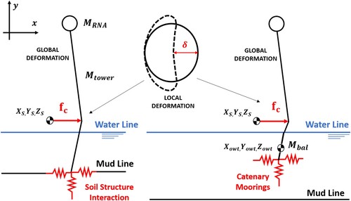
This way, when disregarding the hydrodynamic interaction and the SSI energy dissipation in Equation (Equation3(3)
(3) ), a direct relationship between the structural deformations for a given collapse mechanism and the impact energy can be derived. Such approach has been applied to offshore structures, especially to monopiles and jacket structures, as in the works of Amdahl (Citation1983), Buldgen et al. (Citation2014) and Pire et al. (Citation2018a).
Similarly, when an FOWT is collided by a ship as illustrated in the right-hand side of , the contributions of hydrodynamic and mooring restoring forces can be neglected if the collision time is, as previously explained, much lower than the natural period of the impacted structure's rigid motion. Assuming a perfectly plastic collision, the expression for the total energy dissipation during the collision reduces to:
(4)
(4) which is derived from the combination of the common velocities of the bodies after the collision using Equation (Equation2
(2)
(2) ), and replacing into the energy balance between both initial and final kinetic energies of both ship and FOWT. However, this approximation should be taken carefully in cases where the collision duration is significantly higher than the hydrodynamic response period of the FOWT. If the common velocity assumption is no longer valid and the hydrodynamic and mooring restoring forces can significantly influence the collision response, a decoupled solution is no longer possible. In that case, semi-coupled or fully coupled approaches become necessary when assessing the collision dynamics as discussed in Section 3.3.
Furthermore, it is important to note that depending on the relative dynamic stiffness and the initial kinetic energy of the colliding bodies, a significant amount of energy might be transferred into elastic deformation mechanisms such as global bending and torsion. This is the case, for example, of minor collision events involving lower initial kinetic energies, where the duration of the collision impulse is comparable to the natural period of the structure's lowest vibration mode (Petersen and Pedersen Citation1981). In such situations, the contribution of elastic mechanisms to the energy dissipation cannot be neglected.
Another important factor that should be considered, especially in the case of OWTs, concerns the resulting acceleration of the turbine's topside due to its dynamic elastic response. During a short period just after impact, an elastic shock wave travels along the structure, inducing an acceleration of the nacelle (Pedersen Citation2013). This can be problematic since the equipment located in the nacelle (generator, gearboxes, etc.) is sensitive to high accelerations and can be damaged by such dynamic responses Bela et al. (Citation2017).
3.3. Coupling
Separating physical phenomena that take place in a ship collision event into external and internal mechanisms is a convenient way to understand and approach the problem. However, it is important to highlight that rigid-body dynamics, hydrodynamic effects and deformation mechanisms are actually not independent and may interact significantly depending on the collision scenario.
Consider, for example, a FOWT undergoing impact from an approaching vessel in still-water condition, as depicted in . For each of the involved structures, body-fixed (B) and earth-fixed (O) reference frames can be defined, allowing for a complete description of their 6-degrees-of-freedom (6-DOF) rigid-body motions. Focusing on the FOWT, the first reference is located at its centre of gravity (CoG) and the second is fixed in space, defining its initial position (see ).
Figure 3. Examined FOWT and defined earth-fixed (O) and body-fixed (B) reference frames. (This figure is available in colour online.)
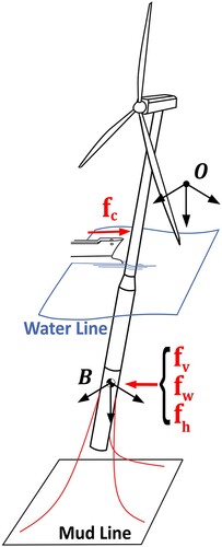
The resulting equilibrium of forces and moments acting on the FOWT is presented in Equation (Equation5(5)
(5) ):
(5)
(5) where
is the total mass matrix given by the sum of rigid-body
and added
mass matrices:
(6)
(6) and
is the total gyroscopic matrix, defined by the sum of rigid-body
and added
gyroscopic matrices:
(7)
(7) In Equation (Equation5
(5)
(5) ), vector
denotes the position of a structure's CoG (associated either to the impacted structure or impacting ship) with respect to the earth-fixed reference and vector
denotes the absolute body-fixed velocity of the FOWT's CoG.
For clarity, Equation (Equation5(5)
(5) ) is arranged so that the terms which concern the external dynamics are grouped on the left-hand side, while the contact force, related to the internal mechanics, appears on the right-hand side. The first term on the left contains the inertia and gyroscopic matrices that govern the rigid-body motion of the structure. Forces and moments for a given hydrodynamic mechanism are then defined by vectors
, where
and
include the wave and viscous damping effects, respectively, while
is the hydrostatic restoring force vector. On the right-hand side is the contact force
, which depends on the position of both impacted and impacting structures (
). Additional forces related to mooring lines, SSI or wind can be included on the right-hand side of Equation (Equation5
(5)
(5) ). Further details on the development of each term can be found in Le Sourne et al. (Citation2001).
As inertial, hydrodynamic and collision forces are all dependent on the structure's rigid body motions and vice versa, the solution of Equation (Equation5(5)
(5) ) is generally not trivial. There are, nevertheless, different ways in which these interactions can be approached when solving Equation (Equation5
(5)
(5) ).
For instance, there are collision scenarios for which external dynamics and internal mechanics can be completely decoupled when colliding structures and surrounding fluid are treated as an undamped system, as explained in Section 3.1. Hydrodynamic forces acting on the impacted structure are then taken into account in the form of a constant equivalent added mass coefficient (Petersen Citation1982) and the solution of Equation (Equation5(5)
(5) ) is greatly simplified as hydrodynamic, inertial and contact terms can then be evaluated separately. Such methods are referred to as decoupled approaches.
There are scenarios, however, where hydrodynamic effects are strongly coupled to rigid-body motions and the assumption of a constant equivalent added mass coefficient might lead to inaccurate results. This is the case, for example, of long duration impacts: as equivalent added masses depend on the collision duration and transient collision forces (Motora et al. Citation1971), the equivalent added mass varies with time and the assumption of a constant coefficient becomes unrealistic. Besides, Brown (Citation2002), Tabri et al. (Citation2008) and Yu and Amdahl (Citation2016b) demonstrated that although decoupled approaches generally give reasonable estimation of the dissipated energy, the predicted damage extent might not be as accurate, especially in the case of oblique collisions. Moreover, encompassing different hydrodynamic components such as added mass, wave and viscous damping, and hydrostatic restoring force into a single term is not realistic in many collision scenarios, as these might have different degrees of influence over the motion of the colliding structures and the consequent resulting damage. Investigations on this topic can be found in Kim et al. (Citation2021) for ship grounding and collisions, in Le Sourne et al. (Citation2001) for ship-submarine collisions and in Echeverry et al. (Citation2020) for ship-FOWT collisions.
Moreover, alternative approaches to solve external dynamics and internal mechanics simultaneously can be grouped into two main categories: semi-coupled and fully-coupled methods.
In Semi-coupled methods, an iterative time-stepping algorithm is applied to solve alternatively both sides of Equation (Equation5(5)
(5) ) by considering coupled hydrodynamic, inertial and contact forces without the need for decoupling simplifications. Generally, a sub-cycling procedure is adopted in order to reduce the overall calculation time. This means that instead of evaluating the hydrodynamic loads at each ‘structural’ time-step, this is done only for a defined number of steps. Hydrodynamic models such as strip theory and linear potential flow theory are usually applied to calculate hydrodynamic loads, while the structural response is determined with results coming from NL-FEA or simplified methods based on plastic limit analysis. Semi-coupled methods can be advantageously used when an uncoupled approach is not suitable, providing accurate results without the high computational cost associated to an explicit modelling of the fluid. Examples of such approach can be found in methodologies developed by Le Sourne et al. (Citation2001), Brown (Citation2002), Tabri et al. (Citation2010), Yu and Amdahl (Citation2016a), Yu, Amdahl, et al. (Citation2016), Yu, Shen, et al. (Citation2016), Mujeeb-Ahmed et al. (Citation2020), Kim et al. (Citation2021) and Yu and Amdahl (Citation2021a).
In fully coupled methods, coupled interactions between hydrodynamic and structural forces in Equation (Equation5(5)
(5) ) are evaluated simultaneously at each time step. Generally, both fluid and structural domains are modelled explicitly using techniques such as Arbitrary Lagrangian Eulerian (ALE) and Coupled Eulerian Lagrangian (CEL). Despite the capability of such methods to produce highly accurate results in terms of energy dissipation and resulting damage, extreme computational costs can be a significant drawback. Therefore, fully coupled methods are usually not suitable for industrial applications. Examples of fully coupled approaches are found in Lee et al. (Citation2012), Song et al. (Citation2017) and Rudan et al. (Citation2019). Methodologies exemplified in this section are further detailed in Section 4.6.1.
3.4. Soil–structure interaction
During a collision event involving a fixed OWT, part of the impact load is transmitted to the soil adjacent to its foundation by friction and pressure. The soil composition plays then a key role in determining not only the overall stiffness of the structure during the collision, but also in its post-collision serviceability. In other words, the designer needs to address the post-impact condition of the soil, so the structure remains within its service limit.
Ideally, SSI non-linearities and stratification heterogeneity of soil materials should be considered in a ship-OWT collision analysis. However, it is not always possible, due to either technical or economical reasons, to have a precise soil composition profile for a given offshore location from early phases of the design process. Nevertheless, SSI effects can be accounted for by using simplified methods. An example is the application of linear springs defined with averaged stiffness coefficients to model different soil layers, as shown in . In this way, the lateral displacement ρ and the tower inclination θ can be found using the linear relationship shown in Equation (Equation8(8)
(8) ) for a given lateral force
and overturning moment
.
(8)
(8) where
is the lateral soil stiffness,
the rotational soil stiffness and
the cross-coupling stiffness, as presented in Bhattacharya (Citation2019). This approach, although useful for considering the overall reduction in stiffness compared to a fully clamped model, is only valid for small rotations and fails in capturing essential SSI effects (i.e material non-linear effects and soil reaction through depth).
One way to include stratification combined with soil non-linearity in a numerical model is to use non-linear springs along the foundation depth, where non-linear force-displacement relation are assigned to each spring according to soil reaction curves coming from geotechnical studies (see ). These approaches have been implemented in ultimate strength calculation tools, such as USFOS, for both monopile and jacket foundations, where the piles are discretised into several spring and beam elements according to the soil layer profile given by the user, as explained by Søreide et al. (Citation1993).
Figure 4. Soil idealisation by using non-linear Winkler foundations. (This figure is available in colour online.)
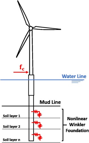
Nevertheless, one of the most accurate ways to account for SSI effects is to perform high fidelity NL-FE simulations using solid elements along geomaterial models, where each soil layer is modelled explicitly throughout its depth. The main drawback of such analyses, besides the significant computational effort they require, is the high-level of expertise required from the designer in terms of geological material modelling and non-linear simulations.
3.5. Mooring interaction mechanisms
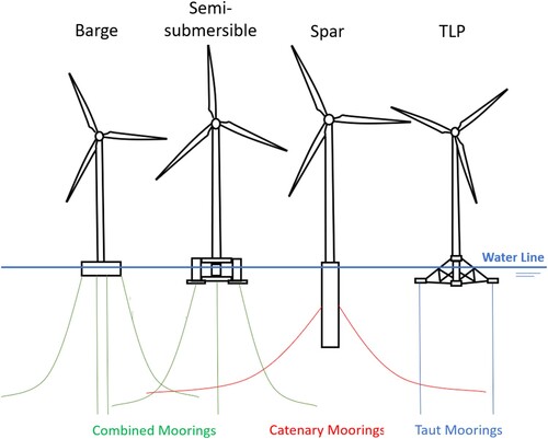
Up to the present, many concepts of FOWT have been proposed based largely on the experience from the oil and gas industry, as mentioned by Ma et al. (Citation2019a). In general, FOWTs are classified within three types of stabilisation systems: buoyancy stabilised (such as semi-submersible or barge floaters), ballast stabilised (such as spar floaters) or mooring stabilised (such as tension leg platforms – TLP). Different mooring arrangements can be found depending on the type of floaters such as catenary moorings, taut moorings, or combinations of both. shows an schematic of the different mooring arrangements for different floating systems used to support wind turbines.
Figure 5. Floater and mooring types. (This figure is available in colour online.)
In moored floating platforms, the external loads coming from wind, currents, waves and tides are finally transmitted to the mooring arrangement, balancing this way with either the internal forces developed through the line, and/or the anchor system. Moreover, during the mooring's motion, hydrodynamic loads coming from added mass effects and viscous damping forces, may influence significantly the floater response, especially during fast loading scenarios when either the mooring system stiffness, and/or its inertial properties, are significant
Different models have been developed for the calculation of restoring forces arising from a mooring arrangement. Either quasi-static or dynamic models can be used depending on the floater response for a given load case. The quasi-static approach has the advantage of being computationally inexpensive, as generally closed form solutions are readily available and can be easily implemented. When dynamic effects become significant (i.e. large displacements of the floater in short spans of time), quasi-static approaches are replaced by models such as finite element, finite difference and lumped mass analyses. These methods are described in Section 4.8.
3.6. Wind loads
The wind plays a critical role in the overall response of an OWT subjected to ship impact. Wind thrust forces acting on the rotor induce some deflection of the blades, decreasing blade-tower clearance and increasing tower bending moments Yu and Amdahl (Citation2021b). Moreover, the global dynamic behaviour of the structure is strongly influenced by the coupled response of the rotating blades and the impacted tower. For floating turbines, the consideration of aerodynamic loads becomes even more critical given that the floater's rigid-body motions and the mooring lines also interact with the overall dynamic response of the structure.
According to Hansen (Citation2015), assuming an ideal rotor, the wind thrust force at the tower top can be derived as:
(9)
(9) where
is the thrust coefficient that depends on the operation state of the rotor,
is the air density, A the rotor disc area and
the wind speed. Furthermore,
can be decomposed as:
(10)
(10) where
is the mean wind speed,
the turbulent wind speed and
the velocity of the tower top, which can either be positive or negative depending if the rotor-nacelle assembly (RNA) is translating up or downwind. By introducing Equation (Equation10
(10)
(10) ) in Equation (Equation9
(9)
(9) ), the thrust force can be separated in three components: the static mean thrust force, the dynamic turbulent thrust force and the dynamic damping force. Essentially, as the RNA moves in the direction of the wind, the thrust force decreases and as it moves against the wind, it increases. This effect acts as a source of damping, being directly related to the velocity-proportional term in the equation of motion of the OWT (Salzmann and Van der Tempel Citation2005). Furthermore, it is more pronounced in floating wind turbines which are more prone to experience stronger tower motions.
Methods used to model the wind effects in OWT-ship collisions are summarised in Section 4.9.
4. Structural damage analysis
4.1. Introduction
This chapter presents and discuss different methodologies to analyse the structural damage resulting from the collision between a ship and an offshore wind turbine.
4.2. Experimental methods
One of the main difficulties in ship collisions modelling is that verification against large-scale experimental tests is not feasible in most cases due to inherent economic and technical complications. There have been few experimental campaigns involving full- or large-scale collision events, the most well-known being the side collision test of two inland waterway vessels carried out in the Netherlands and reported by Vredeveldt (Citation1992).
Furthermore, small scale experimental testing of ship–ship collisions is rare and most of the available works focus either on the external dynamics of the bodies, as in the experiments carried out by Tabri et al. (Citation2008), or on the internal mechanics of the colliding bodies, as presented by Oshiro et al. (Citation2017). This lack of small-scale experiments is directly related to high uncertainties that are associated with the commonly used similarity principles (i.e. geometrical and material). Not only because imperfections and alterations of the heat-affected zone are not considered in a reduced scale, but also because the common assumption of equivalent impact velocities between the models introduces a scaling factor in the strain rates. Therefore, the combination of these effects can potentially change the failure mode of the scaled structure compared to the real one, as pointed out by Jones (Citation1979) and Oshiro et al. (Citation2017).
Alternatively, there has been a great effort on scaled experimental tests of ship structural sub-assemblies such as side panels (Hagiwara et al. Citation1983; Paik et al. Citation1999; Calle, Oshiro, et al. Citation2017) and bulbous bows (Amdahl Citation1983; Yamada Citation2007; Oshiro et al. Citation2017), where the use of larger scales is feasible. The main purpose of these experiments is to observe the collapse mechanisms of different structural members in a collision event, and to quantify the reaction loads arising from such deformations in the form of contact force-penetration curves, which serve as validation references for simplified and discrete numerical models. The reader is referred to the works of Ehlers (Citation2011) and Liu et al. (Citation2018) for a wider review of experiments carried out for ship–ship collision and grounding events.
Experimental research regarding ship collisions against OWT is extremely scarce. In the work of Jia et al. (Citation2020), structural loads arising from a service vessel collision against a 4 MW OWT monopile were recorded using strain gauges at the tower's bottom and blade's root for two loading cases: a normal operating condition and an OSV collision against the OWT's rubber fender. A comparison of the loads in both cases was then performed, and although the increase of bending moments is observed, they concluded that impact loads coming from normal service vessel operations did not represent a threat to the structural integrity of the OWT.
On the other hand, Cho et al. (Citation2013) performed several impact tests on scaled tubular H-shaped braces of an OWT tripod structure, where the dimensions of the models and the striker properties were varied. Results of these experiments were later used in the work of Cerik et al. (Citation2016) to quantify the modelling uncertainties present not only in numerical models using commercial NL-FEA packages, but also in previously developed simplified models based on rigid-plastic analysis. Moreover, in the work of Amdahl (Citation1983), an extensive experimental campaign was carried out for different ship impact events, where experimental tests of bow-bracing and stern-bracing impacts using scaled deformable bow substructures were included and compared with simplified formulations based on rigid-plastic analysis. The application of such formulations has been extended successfully to study impact events as shown in the works of Yu and Amdahl (Citation2018a, Citation2018b).
Nevertheless, according to the author's knowledge, no full- or large-scale experimental work regarding ship collisions against OWT or FOWT structures has been documented up to now. Therefore, the error quantification of most of the developed simplified methods relies solely on results coming from experimental campaigns carried out in the past for ship–ship collisions, or by data extracted from high fidelity non-linear finite element models, whose output quality not only depends on the skills of the analyst, but also on the capabilities of the simulation tool (see ).
Figure 6. Interaction and validation of the results obtained by experimental testing and mathematical modelling of ship collision events. (This figure is available in colour online.)
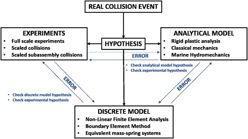
Further experimental work would be fundamental to better understand the response of OWTs subjected to ship collisions, not only to improve and validate analytical or numerical discrete models, but also to quantify their respective accuracy versus computational effort, which is extremely important for the analyst along the different design stages of an OWT. This is particularly true in the case of FOWTs, where a validation of the discrete numerical models is a priority due to the high coupling between the structural, hydrostatic, hydrodynamic, wind and mooring restoring forces as discussed in Sections 3.1–3.3.
4.3. Analytical methods
As previously discussed in Section 3.1, external dynamics and internal mechanics are often assumed to be decoupled. This strong hypothesis, initially proposed by Minorsky (Citation1959), is commonly used in ship collision analysis, since it allows for a considerable simplification of calculations, whilst yielding acceptable accuracy levels for most ship–ship collision scenarios. This assumption is therefore, the basis for most simplified analytical methods, which are particularly suitable for risk-based assessments or optimisation routines, contexts where minimising calculation cost is the main interest of designers, as simulations of large numbers of collision scenarios are typically required and moderate accuracy is normally sufficient.
This section presents an overview of analytical methods for ship collision analyses, with special attention to methods applicable to collisions between ships and OWTs. It is divided into methods focused on the external dynamic and the internal mechanics.
4.3.1. External dynamics modelling
Simplified methods focused on the external dynamics of colliding bodies typically rely on strong assumptions regarding the deformation behaviour of the structures and also the effects of the surrounding fluid.
For instance, Pedersen and Jensen (Citation1991) and Pedersen and Zhang (Citation1998) presented closed-form expressions to calculate the energy released into crushing and the impact impulse for arbitrary ship collisions. The procedure consists, essentially, in assuming that deformation is constrained to a small local impact zone and that hydrodynamic effects can be simplified with a constant added mass coefficient (see Section 3.3), which allows for the application of momentum and energy conservation principles. The dissipated energy can be obtained by integrating the contact force and relative rigid-body motions. These are, however, limited to 3-DOFs on the horizontal plane (surge, sway, and yaw).
Examples of applications of this method to ship–ship collisions, ship collisions with rigid walls and ship collisions with flexible offshore platforms can be found in the book by Zhang S et al. (Citation2019). A variation of this approach has also been developed by Jonge and Laukeland (Citation2013) for ship collisions against spar platform. In the latter, the formulation is adapted to describe the out-of plane pitch rotation of the spar.
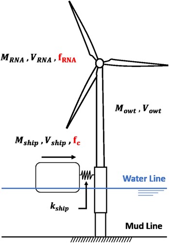
The method by Pedersen and Zhang (Citation1998) has also been extended to a fixed OWT impacted by an approaching vessel in the work of Pedersen (Citation2013). Similarly to what is done for collisions against offshore platforms, the model is simplified as a mass-spring system, where generalised masses represent the striking vessel, the wind turbine and the nacelle (see ). Force-displacement relationships for the collision force and for the force acting on the topside are then constructed with generalised stiffness coefficients. Finally, applying momentum and energy conservation principles, the maximum collision force, dissipated energy and the resultant acceleration at the nacelle CoG can be calculated.
Figure 7. Simplified model of a collision between a flexible OWT and a supply vessel. Adapted from: Pedersen (Citation2013). (This figure is available in colour online.)
Recently, a similar procedure was adopted by Song et al. (Citation2021) for the analysis of a monopile-supported OWT subjected to simultaneous ship impact and wind loads. The authors assume that there is no interaction between the wind force acting on the topside of the turbine and the collision force, and the response of the structure is then described by a linear summation of resulting deflections associated to each independent load. On one side, the response due to the wind is calculated with simple beam theory, considering that the OWT is a cantilever with varying cross-section. On the other side, impact force-stiffness relationships are defined with an additional linear damping term that includes structural (Rayleigh), wave radiation, soil and aerodynamic damping coefficients.
Despite the wide range of applications available for the method proposed by Pedersen and Zhang (Citation1998), results might be unrealistic when using this 2D approach for scenarios where motion components on the vertical plane have a significant role. Therefore, a methodology capable of dealing with not only 2D, but also 3D motions has been proposed by Liu and Amdahl (Citation2010). Based on the works by Stronge (Citation2018) on rigid body impacts, the method relies on the definition of global and local reference systems. Equations of motion are solved in the local coordinate, allowing the energy dissipation along each of the 3D axes to be obtained. The method was applied to assess energy dissipation in a ship collision against an iceberg, where results are highly dependent on the vertical geometry of the colliding bodies.
4.3.2. Internal mechanics modelling
As discussed in Section 3.2, simplified analytical methods for the internal mechanics of ship collisions against offshore structures usually apply plastic limit analysis to assess the response of individual structural elements such as plates, girders and tubular members.
The first researches in the collision analysis using semi-analytical approaches, called Idealised Structural Unit Method (ISUM), were proposed by Yukio and Rashed (Citation1984), Ito et al. (Citation1985) and Paik (Citation2018). In this approach, the structure is divided into large elements, the so-called structural units, for which the plastic deformation energy coming from assumed collapse mechanisms is described by either a closed-form expression, or a pre-defined force-displacement curve. The main advantage of such method relies on the fact that a substantially lower number of elements is required to describe a full structure as compared to standard NL-FEA, thus resulting in acceptable accuracy with short calculation times.
In more recent years, Søreide et al. (Citation1993) developed the software USFOS, where each large structural member in an arbitrary structure can be considered as one beam-column element. These elements consider non-linearities such as large deformations, concentrated plasticity in the form of plastic hinges at both element extremities and mid-span, and elastic plastic column buckling plasticity. Effects of large displacements, and coupling between lateral deflection and axial strain, are implemented through non-linear strain relations, which gives an accurate representation of element behaviour, including membrane effects and column buckling. However, the shape of the striker is restricted to a plane indenter. This might be acceptable for some structures such as bottom fixed OWT, but not for floating impacted structures such as FOWT, where deformations and rigid body motions of both involved structures may be highly coupled. Moreover, Yu and Amdahl (Citation2018b) did an extensive review of the methods used to analyse the response of tubular offshore structures subjected to mass impacts, covering different aspects from material modelling to ship impact loading, energy absorption,residual strengths, global and local responses.
Another tool based on the super-element method is SHARP (Le Sourne et al. Citation2012), used for ship–ship collisions, where the effects of hydrodynamic forces occurring during the ships' rigid body displacement are included. The program is capable of estimating the crushing resistance and energy dissipation for right-angle and oblique ship–ship collisions using super-elements based on typical structural components such as plates, beams and intersections to discretise both striking and struck ships.
Regarding ship-OWT's collisions, different methodologies have been proposed. A theoretical analysis of ship collision with fixed monopile-supported OWT was presented in the work of Pedersen (Citation2013), where starting from the principles of conservation of momentum and energy, algebraic expressions for assessing the maximum values of collision forces were derived, while tower-tip accelerations and energy absorbed during the global deformation of the monopile were retrieved. Furthermore, Buldgen et al. (Citation2014) presented analytical solutions for the complete plastic behaviour of tubular members including local denting, global bending and membrane stretching. For local denting, the model of Wierzbicki and Suh (Citation1988) was extended to consider different impact orientations and positions as well as the shape of the striking ship stem.
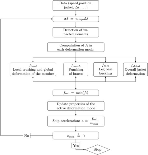
More recently, ship collisions against jacket structures were studied in detail by Pire (Citation2018), who developed a tool based on semi-analytical formulations to assess the deformation of a jacket structure collided by a ship. Starting from the observation of the different damage mechanisms post-processed from numerical simulations (see ), an efficient approach based on the concept of super-elements was proposed combining simplified solutions derived for:
Figure 8. Effective plastic strain on the whole collided jacket. From: Pire (Citation2018). (This figure is available in colour online.)
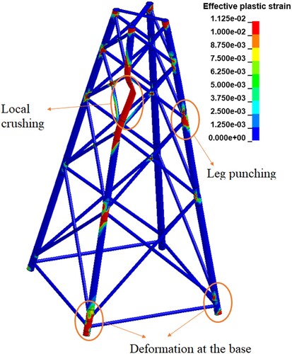
Local denting, global bending and axial stretching of beam elements considering the closed-form expressions proposed by Buldgen et al. (Citation2014);
Punching of legs by compressed braces following the approach documented in Pire et al. (Citation2018c);
Buckling of legs at the base of the jacket as detailed in Pire et al. (Citation2018b);
Overall deformation of the jacket by assembling elastic-plastic beam-column stiffness matrices following the approach implemented in USFOS.
As schematised in , resistant forces are computed at each time step for all four deformation modes and the mechanism related to the lowest force is triggered. As the deformation in one mode may affect the others, their interactions are accounted for in the formulations and updated at each iteration. After modelling a real jacket built and installed in the French coast, the results obtained from this tool were successfully confronted to finite element simulations considering different striking ships, impact velocities and collision angles Le Sourne et al. (Citation2016).
Figure 9. General algorithm including all deformation modes. Adapted from Pire (Citation2018).
4.4. Numerical methods
Numerical methods are nowadays a standard practice in the design of offshore structures against ship collisions, offering a more practical alternative to extremely complex and costly experimental setups. They also present higher levels of accuracy than simplified analytical methods. Non-linear FEA, for instance, has been extensively applied in collision analyses of offshore structures typically used in the oil and gas industry, such as jackets, jack-up rigs and semi-submersible platforms. A large number of studies on the subject have been published in the last decades and comprehensive reviews can be found in Ellinas and Valsgard (Citation1985) and Yu and Amdahl (Citation2018b).
However, when it comes to offshore wind turbines, the literature is still scarce, especially regarding floating offshore wind turbines. Nonetheless, with the increasing interest in these technologies, developments on the field are likely to advance fast. The objective of this section is to present a review of available numerical studies on collisions between ships and offshore wind turbines, either fixed or floating.
4.4.1. Fixed structures
Biehl and Lehmann (Citation2006) carried out finite element simulations of lateral ship-OWT collisions for different types of vessels and supports, including a monopile, a jacket and a tripod. The study was concerned in particular with the ability of the OWT supports to minimise damage on the ship. Preliminary calculations of resulting stresses, displacements and contact forces acting on the OWT due to quasi-static loads (gravity, operation, SSI, wind and waves) were performed with LS-DYNA's implicit solver. For the explicit collision simulation, the ship's motions, influenced by the surrounding fluid, were calculated using the MCOL rigid-body subroutine available in LS-DYNA (see Section 4.6). This study provided an overview of different failure modes for different supports. It was concluded that tripods considered were less capable of absorbing energy through deformation, which resulted in more severe damage inflicted to the ship. Moreover, for monopiles and jackets, collapse was shown to represent a major risk, since the fall of the upper structure on the ship could be very damaging for the latter.
A few years later, Amdahl and Holmas (Citation2011) performed simulations of a drifting tanker colliding against a jacket-supported OWT using USFOS. While the jacket was modelled with joint-to-joint beam-column elements, tubular beams and non-linear springs were used to represent the piles and the depth-dependent soil stiffness. The tower was also modelled with tubular beam elements, which are capable of a reasonable approximation of global bending, but cannot capture the local buckling that occurs at the transition piece. However, to properly represent such localised effects, USFOS allows for a hybrid meshing technique employing shell elements in areas of interest. It is also important to note, that the ship was not explicitly modelled, but rather defined as a combination of non-linear springs and a concentrated mass, that described its stiffness and inertia properties respectively. This modelling approach can be quite advantageous in terms of computation time as compared to conventional NL-FEA using shell elements and contact algorithms (e.g. LS-DYNA and ABAQUS). Nevertheless, the requirement of a preliminary calculation of contact forces may be a drawback of the method. More details on USFOS can be found in Section 4.3.2. Furthermore, this study enabled an assessment of the failure process of the jacket OWT, demonstrating that the struck leg suffers major deformation leading to a collapse of the whole structure when the tanker approaches at 2 m/s.
A numerical study on ship collisions against jacket supported OWTs was also performed by Le Sourne et al. (Citation2015) using LS-DYNA. The objective was to investigate the crushing response and energy dissipation for different striking ship velocities and to analyse the influence of factors such as gravity loading, inclusion of the wind turbine tower and soil stiffness. It is worth to note that simulations with both rigid and deformable striking ships were performed. The study demonstrated that a leg impact was more damaging than a brace joint impact for an OSV approaching at 6,m/s, since the leg was less capable of distributing strain energy to other structural members, which resulted in rupture. Gravity loading and the presence of the wind turbine did not seem to affect significantly the response of the OWT. Furthermore, results obtained for the jacket considered suggested that assuming this latter to be clamped into the ground was acceptable. Finally, simulations with two deformable ships, an OSV bow and the side of an ice class bulk carrier, indicated that considering a rigid impactor for the second one is also a reasonable assumption.
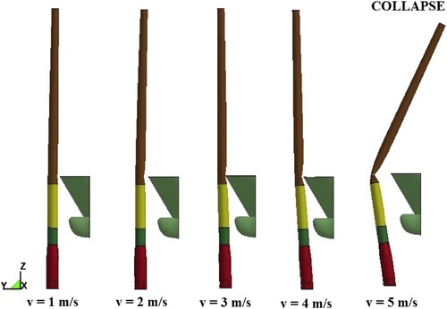
Bela et al. (Citation2017) performed a similar parametric study on LS-DYNA for a monopile supported OWT impacted by rigid and deformable OSVs, where the effect of different approaching velocities and impact locations, as well as the influence of wind loads and soil stiffness were examined. Results demonstrated the importance of the impact velocity on the OWT's response, with characteristic deformation behaviour ranging from a quasi-elastic response associated to minor plastic deformations for lower velocities, through large plastic deformations and ultimately collapse when the ship's velocity exceeds 5 m/s (). The effect of the wind appeared to be quite significant, especially when the impact force acted in an opposite direction. In this scenario, for a normal wind operation condition, a ship approaching at 3 m/s led to the collapse of the OWT tower. It was also shown that neglecting the soil flexibility could result in an overestimation of plastic deformations. Finally, simulations demonstrated that the nacelle can suffer high accelerations, resulting in damage of sensitive internal equipment.
Figure 10. Global deformation of the monopile OWT for different impact velocities. From: Bela et al. (Citation2017). (This figure is available in colour online.)
Further investigations on the transient response of a monopile OWT subjected to simultaneous ship impact and wind loads was recently performed by Song et al. (Citation2021). Numerical simulations with LS-DYNA were used to validate a simplified analytical method for the evaluation of the topside motion based on Pedersen's work (Pedersen Citation2013).
4.4.2. Floating structures
When it comes to floating structures, aspects such as hydrodynamic effects and mooring lines are highly important, as discussed in Section 3. These factors add complexity to numerical model setups and render ship-FOWT collisions substantially different from collisions involving fixed supports, since at least semi-coupled approaches are necessary to model both external dynamics and internal mechanics.
For example, Echeverry et al. (Citation2020) performed a series of investigations on the structural behaviour of a spar FOWT subjected to ship collisions using LS-DYNA in conjunction with MCOL. The FOWT's response and the influence of parameters such as gravity loading, mass of the nacelle, mooring lines, ballast, hydrodynamic forces and deformability of the impactor were examined. As depicted in , the main deformation modes observed on the FOWT were:
Plastic indentation at the impact zone
Beam-like elastic response of the global structure
Buckling at the interface between the ballast tank and the floater
Buckling at the interface between the tower and the nacelle
Figure 11. Deformation modes observed in a FOWT subjected to hip impact. From: Echeverry et al. (Citation2020). (This figure is available in colour online.)
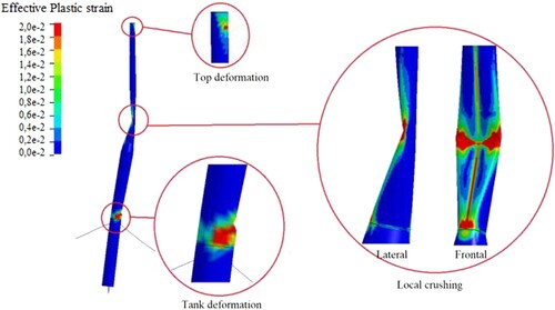
It was also demonstrated that neglecting hydrodynamic effects resulted in a significant underestimation of the collision force. Hydrostatic restoring forces acting to counter the spar's resulting pitch and heave motions were the main source of energy dissipation due to the surrounding fluid. Moreover, the quite important mass of the nacelle and huge mass of the ballast tank have a strong influence on the FOWT's response. Especially in the very first moments of impact, when the structure's beam-like elastic global bending subjects the nacelle to high acceleration levels. For lower ship initial kinetic energies, the contribution of the elastic deformation to the internal energy was even more pronounced. On the contrary, it was shown that mooring lines deformation have a more significant influence on long-term FOWT rigid body motions.
Another numerical ship collision study on a spar FOWT was recently documented by Zhang and Hu (Citation2021). They applied the user-defined LOADUD subroutine in LS-DYNA (see Section 4.6) to include hydrodynamic as well as aerodynamic and mooring loads in the collision model. Potential flow theory was employed to calculate radiation forces including water added mass at infinite frequency and wave radiation damping. Hydrostatic restoring forces were also taken into account, but without considering large rotational motions. The wind thrust was calculated with a simplified formulation assuming a constant relative wind velocity. Additionally, moorings were not modelled explicitly with finite elements, but rather through a linearised model that does not consider inertia and damping. This was a preliminary study with particular focus on the global motions of the spar and the resulting acceleration of the nacelle.
Finally, there are some recent studies on other types of floating structures. For instance, Sha et al. (Citation2017, Citation2019) investigated global and local responses of a floating bridge girder collided by a ship. First, a simulation in LS-DYNA was carried out in order to obtain detailed local damage occurring in both structures. The resulting force-displacement curve was then used to define the non-linear springs and nodal mass system employed to model the ship's bow collision in USFOS, from which the global response of the floating bridge is estimated. A similar approach was used by Yu et al. (Citation2019) to analyse a ship collision against a floating fish farm.
4.5. Material modelling
During a ship-OWT impact event, structural members in the collision zone are subject to high-intensity stresses and localised deformations for a short period, where factors such as prescribed failure criteria, crack propagation behaviour, and strain rate effects become significant. Therefore, the selection of adequate constitutive models for either metallic or cementitious materials becomes crucial for obtaining meaningful results, especially when carrying out NL-FEA.
Moreover, the inclusion of more compliant concrete structures as the OWT floater prototypes introduced by BW Ideol (Ideol Citation2018) and Olav Olsen (Explorer Citation2021) will require additional research for understanding and foreseeing the response of these new floating concrete structures to impact events. This was not explored before, as the offshore concrete structures used in the past, almost exclusively in the oil and gas industry, had large thicknesses and were less prone to fail under the impact of Offshore Service Vessels (OSV), as pointed in the work of Amdahl and Furnes (Citation1980). An overview of the material models usually used in ship-OWT collision analyses is presented in this section.
4.5.1. Steel
Offshore wind turbines structures are conventionally constructed with low to medium grade structural steels with yield strengths varying from 240 to 355 MPa. Mechanical properties of mild steels for structural design purposes are usually extracted from uniaxial tensile tests on so-called dog-bone specimens under the scope of an accepted standard. The mechanical behaviour is normally synthesised into an engineering stress-strain curve, where the initial yield stress , the ultimate tensile stress
and stress at fracture
are identified (see ).
Figure 12. Engineering Stress–Strain curve for mild steel. (This figure is available in colour online.)
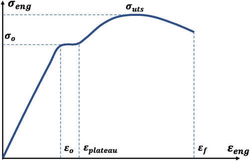
The increase of plastic stress due to hardening may be described either by a power hardening law, which depends on the effective plastic strain , or directly by a piece-wise hardening curve. For mild steel, accounting for the existence of a yield plateau which last up to the beginning of hardening at
, the power-law and yield function takes the form:
(11)
(11)
(12)
(12) where the hardening parameters K and n are determined experimentally. In Equation (Equation12
(12)
(12) ), the yield function Y relies on the second deviatoric invariant (
) and the yield stress
, whose evolution depends on the hardening law adopted, the most used one in ship collision analyses being the isotropic hardening.
A widely used model to account for the strain rate effect was initially proposed in 1957 by Cowper and Symonds (Citation1957), who proposed a scaling of the static stress with a dynamic hardening factor based on the strain rate :
(13)
(13) where C and p are parameters calibrated from dynamic tensile tests. As suggested by these authors, values of
and p = 5 are nowadays commonly used for mild steels, while
and p = 5 may be used for high strength steels according to Paik and Thayamballi (Citation2003).
Nevertheless, it is worth noting that ship collision against OWT should occur at relatively low speed (less than 10 m/s) and, as demonstrated recently by Cerik and Choung (Citation2020), the effect of strain rate on the structural response of both the striking ship and struck structure is generally limited. As a consequence of the considerable uncertainties related to strain rate effects, as well as the difficulties in their implementation, it was recommended by Yu and Amdahl (Citation2018b) that the strain rate effects should be disregarded in analyses of ship collisions against offshore structures.
The main challenge when modelling the steel behaviour is actually to accurately capture fracture initiation and propagation, which are localised phenomena on the length scale of plate thickness and consequently difficult to capture with large shell elements. In addition, fracture depends highly on the material stress state and its modelling is very sensitive to the mesh size adopted. Some fracture criteria that account for stress biaxiality or triaxiality have been proposed in the literature for structures modelled with large-sized shell elements (several times the shell thickness). For instance, the BWH (Bressan–Williams–Hill) (Alsos et al. Citation2008) and RTCL (Rice–Tracey and Cockcroft–Latham) (Tørnqvist Citation2003) fracture criteria have shown reasonable and consistent predictions in several benchmark studies based on small and large scale tests (Calle and Alves Citation2015; Storheim et al. Citation2015; Calle, Verleysen, et al. Citation2017).
More recently, the history of material deformation was shown by Kõrgesaar (Citation2019) to have also a strong influence on the simulation results. Hence, impact simulations with two stress state dependent fracture criteria that provided the same failure strain, but accounted damage history differently, led to very different force-displacement curves.
The influence of the failure mode was investigated by Woelke et al. (Citation2018) who highlighted the difference between fracture behaviour of thin sheets under plane strain bending and tension, showing that fracture initiation was delayed under bending dominated loads. Approaches that can distinguish between the membrane and bending deformation have been recently formulated by Costas et al. (Citation2019) and Pack and Mohr (Citation2017). This latter was recently shown by Cerik et al. (Citation2019) to give consistent element size independent results for a stiffened plate ruptured under membrane tension.
Numerical simulations of different ship structure components were carried out by Kõrgesaar and Storheim (Citation2020) using different mesh sizes and fracture criteria, including approaches that can distinguish between membrane and bending deformation modes. In this study, it appears that Pack and Mohr's approach (Pack and Mohr Citation2017) does not yield better accuracy compared to approaches that do not distinguish deformation modes. Instead, Cockcroft–Latham failure criterion associated to a bending mode indicator to account bending damage (Costas et al. Citation2019) gave the least scatter among the different analysed cases.
4.5.2. Concrete
The uniaxial behaviour of concrete is non-linear from the very beginning of the load application, whose initial mechanical properties are governed mainly by the mixture characteristics and drying time. For characterising the behaviour of plain concrete, uniaxial compression tests are not enough and typically, additional tests under different confinement pressures are required. Usually, confinement pressures increase the ultimate load that the material can withstand in compression, therefore changing the failure mode from a brittle to a ductile response. The large number of parameters required for defining constitutive material models for concrete, as compared to steel, makes the collision events with reinforced concrete (RC) offshore structures even more complex to analyse numerically.
Different constitutive material laws have been proposed to describe concretes, the most used in impact problems being the Karagozian and Case Concrete (KCC), the Winfrith Concrete Model (WM) and Continuous Surface Cap Model (CSCM), which have been implemented in NL-FEA packages such as LS-DYNA and validated for different applications as shown in Wu et al. (Citation2012) and Saini and Shafei (Citation2019). The principal difference between these constitutive concrete models resides on how the invariants () of the Cauchy stress tensor, and its deviatoric contribution, are taken into account for obtaining a yield function (see Equation (Equation14
(14)
(14) )), as well as how the crack criterion is implemented.
(14)
(14) When performing numerical analysis of RC structures in impact events, the following features of the concrete materials are desirable (Schwer Citation2010; Wu and Crawford Citation2015):
A constitutive model for plain concrete that models shear dilation, pre-peak hardening, post-peak softening, modulus reduction and irreversible deformation
Crack law for tension and compression which allows tracing localised damage and propagation
Concrete-reinforcement bonding
Adequate unloading behaviour
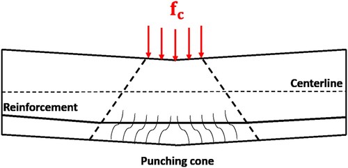
Ideally, the cracking subroutine of the concrete material should be able to capture properly punching shear failure in the structural element, as this is the most expected failure mode to be triggered during a collision event against a RC structure. This failure is characterised by a conical shape with cracks that travel from the backside of the member, up to the surface where the concentrated load is applied, as shown in .
Figure 13. Punching cone in Reinforced Concrete elements. (This figure is available in colour online.)
In the engineering practice, RC members are normally checked for punching shear failure using relations described in design codes, most of them being formulated for static applications or extended to dynamic loads by using Dynamic Amplification Factors (DAF). However, punching shear failure triggered by dynamic loads, as the ones arising from collision events, is difficult to assess not only as a result of the high variation of the contact load during the impact, but also due to the contact area changes caused by the ship's deformation. This was addressed in the work of Sha and Amdahl (Citation2019), where a ship collision against an RC floater was studied numerically. In this study, a comparison of the contact force obtained through NL-FEA and a dynamic punching criterion, based on the formulations proposed in the Eurocode 2, was performed. For the analysed thicknesses and impact energies, the procedure proposed by the authors for checking dynamic punching was able to provide accurate results for establishing a punching limit.
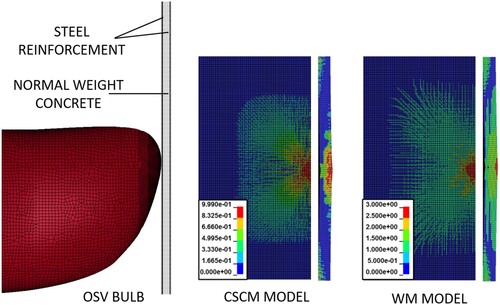
On the other hand, the capabilities of different concrete models were explored in ship collision events in the work of Marquez et al. (Citation2021), where the impact of an OSV against an RC slab, with similar characteristics to the ones found in the Floatgen FOWT substructure of BW Ideol (Ideol Citation2018), was studied. In this work, although similar force-displacement curves were obtained for the different concrete material models, several numerical instabilities where observed when exposed to different stress-states scenarios, or when the concrete strain rates were included. Moreover, all the studied materials included both tensile and compressive damage formulations, which allowed for a clear formation of a punching cone in most of the collision cases investigated. However, the punching damage extent varied significantly between the different models, as shown in , introducing therefore additional uncertainties regarding the assessment of the structure shear punching capacity using NL-FEA.
Figure 14. Ship collision scheme and damage contours obtained with different concrete materials for an impact energy of 0.09 MJ (2000 Ton OSV with an initial velocity of 0.3 m/s). From: Marquez et al. (Citation2021). (This figure is available in colour online.)
Moreover, simplified methodologies for studying impact events against RC structures have been widely used in medium and high velocity loading applications, such as missile impact, blast loading and rock falling events. A wide overview on these methodologies is presented in the work of Daudeville and Malécot (Citation2011). Usually, they consist of spring-mass systems which are built using simplified non-linear RC moment-curvature relations, as well as closed-form relationships for the contact forces arising during the impact (i.e elastic-perfectly plastic assumptions, Hertzian contact laws, among others), this way avoiding the high computational cost of the NL-FEA in the preliminary design stage, or in parametric analyses.
These models have proven to be accurate enough for obtaining both contact forces and kinematic behaviour of the collided bodies during the impact, as shown in works such as Fujikake et al. (Citation2009), Fan et al. (Citation2019) and Micallef et al. (Citation2014) for low velocity impacts. On the other hand, although there has been numerous research works in ship collision against RC structures such as bridges – see for instance the works of Consolazio and Cowan (Citation2003) and Sha and Hao (Citation2013) – there is still little research regarding the collision assessment of more compliant RC structures such as the ones found in FOWT's.
4.6. Coupling modelling
In this section, the semi-coupled and fully coupled approaches presented in Section 3.3 are further detailed. Studies applying these techniques are presented.
4.6.1. Semi-coupled methods
There has been a great effort in the development of methods capable of dealing with collision scenarios where external dynamics and internal mechanic are strongly coupled, such as collisions involving FOWTs. In these scenarios, simplified decoupled methodologies are generally not accurate, while fully coupled methods, despite their capabilities to yield realistic results, require extreme computational resources. Thus, semi-coupled methods offer an interesting compromise, presenting good accuracy with moderate computation cost. There are numerous examples of semi-coupled methods in the literature.
Petersen and Pedersen (Citation1981) and Petersen (Citation1982) for instance, presented one of the pioneering semi-coupled procedures to simulate the horizontal motions of colliding ships and offshore structures. They assumed that deformations were confined to the contact area and that the collision force-displacement relationship was known beforehand. In this manner, the structure's stiffness could be modelled using equivalent non-linear springs. In addition, transient hydrodynamic forces were calculated using linear potential-flow theory. Constant added inertia force (with respect to an infinite wave radiation frequency) and impulse response functions for the wave damping force (dependent on the radiation frequency) were applied to the structure via a strip approach. The main disadvantage of this method resides on the requirement of a preliminary knowledge of the force-displacement curve, which limits its applicability. Additionally, the model is restricted to motions in the horizontal plane. Tabri (Citation2010) proposed a similar method, however extended to 3D motions. In this case, collision forces were estimated by integrating normal and tangential traction components along the contact surface of the colliding ships. The global dynamic bending response of the ships' hull and sloshing effects due to partially filled tanks were also considered in this work.
Another noteworthy example of a semi-coupled method is the Simplified Collision Model (SIMCOL) program developed in 2002 by Brown (Citation2002) for probabilistic ship collision assessments. SIMCOL uses a time-stepping algorithm, combining simplified analytical methods for internal mechanics and external dynamics. For the structural response, depending on the struck member, closed-form solutions, such as the well-known relationship for volume of structural damage and energy dissipation proposed by Minorsky (Citation1959), are applied. External dynamics calculations are similarly limited to horizontal motions and take hydrodynamic effects into account by considering constant added mass coefficients. The method is suitable for risk-based analyses and optimisation models, but is restricted to ship–ship collisions.
The semi-coupled approaches mentioned so far assume different simplifications for the structural response of colliding bodies, which might be sufficient in some scenarios. However, in cases where a detailed assessment of local damage is necessary, methods such as NL-FEA are required. An example is the LS-DYNA/MCOL package, where the NL-FEA code LS-DYNA is combined with the rigid-body dynamics program MCOL. Initially developed by Mitsubishi (Le Sourne et al. Citation2012), MCOL was completely rewritten in 2001 for large rotational motions and included as a subroutine in LS-DYNA. MCOL uses earth-fixed and body-fixed reference frames to describe the 6-DOF motions of the colliding bodies (see ), where inertial and hydrodynamic forces are accounted for, while contact forces are provided by the internal mechanics solver of LS-DYNA.
Regarding hydrodynamic calculations, MCOL considers added inertia due to the surrounding fluid, hydrostatic restoring forces as well as wave radiation and drag damping forces. Similarly to the work of Petersen (Petersen and Pedersen Citation1981), added inertia and wave memory damping effects are described by linear potential-flow theory. For viscous effects, it is assumed that there is no significant boundary-layer separation and therefore, viscous damping forces can be obtained simply as a function of the velocity and drift angle of the defined hydrodynamic surface. Hydrostatic restoring forces, which are dependent on the displacement volume of the body, are calculated in function of its position and a characteristic hydrostatic stiffness matrix. Examples of the use of LS-DYNA/MCOL may be found in Le Sourne et al. (Citation2001, Citation2003), Rudan et al. (Citation2019), Echeverry et al. (Citation2020), Kim et al. (Citation2021), and Paboeuf et al. (Citation2015). MCOL has been also coupled with super-element solvers for ship collision (Le Sourne Citation2007) and ship grounding (Le Sourne et al. Citation2021) fast analyses.
LS-DYNA has also been used as a coupled structural solver in the works of Yu and Amdahl (Citation2016a), Yu, Amdahl, et al. (Citation2016), Yu, Shen, et al. (Citation2016). In these studies, hydrodynamic forces are calculated either through a 6-DOF steady-state maneuvering model based on a series of experimental coefficients (Yu Z and Amdahl Citation2016a), or through linear potential-flow theory (Yu Z, Shen, et al. Citation2016), and then applied to the structure's CoG via the user defined load subroutine LOADUD available in LS-DYNA. Resulting displacements, velocities and accelerations are used to update hydrodynamic loads at each time-step. This method was recently applied in the study of ship collisions against icebergs and floating offshore wind turbines, respectively by Yu and Amdahl (Citation2021a) and by Zhang and Hu (Citation2021).
Both the methodology by Yu and Amdahl (Citation2021a) and the LS-DYNA/MCOL package rely on sub-cycling techniques in order to decrease the total computation time whilst maintaining good accuracy. Additionally, in both methods, hydrodynamic properties of the structure studied need to be obtained with a separate sea-keeping code.
4.6.2. Fully-coupled methods
Alternatively, highly coupled collision events can also be modelled with fully-coupled approaches such as the Arbitrary Lagrangian Eulerian (ALE) and Coupled Eulerian Lagrangian (CEL) methods. By modelling the fluid explicitly, external seakeeping calculations are not required. However, these methods are associated to considerable modelling efforts and computational cost that end up outweighing possible gains in accuracy. Thus, applications of fully-coupled methods in ship collisions are quite limited.
For example, ship collision simulations using the ALE Fluid-Structure Interaction technique available in LS-DYNA were performed by Song et al. (Citation2017) and by Rudan et al. (Citation2019). In the first study, a comparison between results for energy dissipation calculated with ALE and an analytical method based on momentum conservation was performed. In the second one, ALE is compared to LS-DYNA/MCOL. In general, despite ALE's capabilities of realistically modelling fluid-structure interactions, the method can be highly unstable and a cumbersome calibration process of governing parameters and mesh size needs to be performed beforehand. Furthermore, computation time is usually significantly higher due to the explicit modelling of fluid domains. In Rudan et al. (Citation2019), MCOL proved to be stable and considerably faster, even tough it requires input from a seakeeping analysis performed with an external software. No literature regarding the use of fully-coupled methods on offshore wind turbines was found.
4.7. Soil structure interaction modelling
Up to present, there has been a limited number of research works that include soil structure interaction effects in ship-OWT collision events (Amdahl and Holmas Citation2011; Mo et al. Citation2018), and even fewer that discuss in detail the sensitivity of SSI effects in such impact scenarios. In the work of Bela et al. (Citation2017), a set of rotational and translational spring elements with averaged soil properties obtained from experimental measurements were used to include the SSI effects in the analysis of a ship collision against a monopile structure. For the studied impact energies, it was found that the plastic deformation of the impacted OWT was reduced almost by half when including soil effects, while in the elastic dissipation phase the structure oscillations were significantly higher as no soil damping was considered in the model.
A similar approach based on a spring-dashpot systems was followed by Samsonovs et al. (Citation2014), where a two-step impact analysis (i.e. soil static and dynamic conditions) was carried out in order to include the dynamic effects in both stiffness and damping for different soil types. For the studied cases, it was observed that although considering SSI effects reduces the plastic dissipation as compared to a fixed condition, the model presents low sensitivity to changes in soil stiffness, especially in high impact energy cases.
On the other hand, in the work of Biehl and Lehmann (Citation2006), detailed NL-FE simulations including SSI effects on the foundations of monopile, jacket, and tripod structures in sandy soil were carried out. The surrounding soil boundary was modelled explicitly using an elasto-plastic geomaterial law, which was prestressed before the impact simulations with earth pressure at rest. For the studied impact scenarios, the energy absorbed by the soil was significantly high: around 50% of the initial impact energy was transmitted to the soil by the monopile structure, and more than 25% by the tripod for both diagonal braces and tower impact cases. It is worth noting that for these scenarios, the soil deformation energy was higher than the crushed structure one.
Furthermore, the capabilities of high-resolution models for accounting SSI effects in ship impact events were addressed in detail in the work of Fan and Yuan (Citation2014) for ship-bridges impact scenarios, where a comparison against simplified numerical schemes using non-linear springs along p-y curves was also performed (see ). Although no comparison was made against fully clamped conditions, small discrepancies between the modelling approaches were found in terms of pile top deflection at different impact energies, as well as force-deflection curves of laterally loaded piles.
4.8. Mooring modelling
As mentioned in Section 3.5, mooring lines are responsible for transmitting external loads to the seabed. Therefore, a typical mooring system analysis is a process that includes environmental loads, floater hydrodynamic analysis, mooring static analysis, system low-frequency motion analysis and system dynamic analysis (to determine floater response and line tension). This procedure can be done in frequency or time domain.
In FOWT seakeeping analysis, mooring restoring forces can be highly influenced by hydrodynamic effects such as drag forces and water added mass. It has been shown by Hall et al. (Citation2014) that the hydrodynamic damping from the mooring lines contributes significantly to the overall FOWT damping.
However, the influence of mooring dynamic effects in ship-OWT collision has been tackled in the literature by few authors, being addressed for example by Echeverry et al. (Citation2020) and Zhang et al. (Citation2021).
In both research works, ship collisions against a spar-type FOWT moored by a catenary mooring arrangement were studied with numerical simulations. It was shown that the motion of the spar due to the ship impact directly governs the mooring system response, which indeed increases in comparison to the normal operating conditions, remaining in a safe range for a head-on collision up to 3 m/s.
One alternative for including mooring interaction effects in the case of a collision with a ship is idealising the moorings as non-linear springs, whose stiffness can be calculated from closed-form expressions, such as the one proposed by Ma et al. (Citation2019b). However this comes with the drawback of disregarding the dynamic effects of the lines, such as natural vibrations, inertia effects or damping. This method was the one adopted by Zhang and Hu (Citation2021), with a reasonable accuracy when comparing LS-DYNA results with values obtained using the NREL FAST solver (NREL Citation2021b).
Quasi-static or dynamic analyses are the most used to predict the mooring lines response. According to Andersen et al. (Citation2016), quasi-static models can be implemented when low computational costs are desirable, and when the response is not dominated by the mooring system, as it could be the case of some catenary mooring arrangements. In the case of a ship-FOWT collision, the importance of the mooring response depends on the duration of the impact, the floater type and the mooring arrangement.
For example, Hall and Goupee (Citation2015) observed that for platforms with small responses in normal conditions, a quasi-static mooring model is sufficient for capturing properly the motions of the floater. For platforms with a larger response (or when severe environmental conditions are checked), a dynamic mooring line model should be included in the coupled analysis, so that it can account for effects such as mass inertia (including added mass effects), structural and hydrodynamic damping, and vibrations of the lines. The limitations of the quasi-static model, especially for extreme loads, are documented in the work of Hall et al. (Citation2014), while Rudman and Cleary (Citation2016) analyse several configurations of mooring systems and their response to a rogue wave.
Different tools are available to calculate the mooring response for different modelling detailing. MAP++ is an available quasi-static mooring model developed by Masciola et al. (Citation2014), implemented in a former version of FAST software. This simple model solves the non-linear analytical catenary equations for individual lines considering elastic stretching and the apparent weight in water, as well as the force-balance equations at the line-to-line interconnection points.
On the other hand, Hall (Citation2016) created a new module for the mooring analysis at the University of Maine, known as MoorDyn, which was validated with the DeepCwind semi-submersible model test data (Hall and Goupee Citation2015). It is based on a lumped-mass modelling approach that is able to capture mooring stiffness, inertia and damping forces in the axial direction, as well as weight and buoyancy effects, seabed contact forces, and hydrodynamic loads from mooring motion using Morison's equation.
Finally, FEAMooring is a finite-element-based mooring dynamics module developed in Texas A&M University by Yoon Hyeok Bae (NREL Citation2021a). It calculates mooring-line reaction forces at the fairlead positions of the floating platform considering mooring dynamics, including inertia and drag forces at each line element. Moreover, different commercial tools for the analysis of mooring lines have also been used in industrial and research applications of FOWT design, such as the commercial software Orcaflex by Orcina (Citation2021), which contains a lumped-mass-based mooring line model that is capable of computing wave-kinematics-induced cable loads. Likewise, Mimosa/SESAM by DNV (Citation2021) is a tool able to compute static and dynamic mooring tensions, while Ariane by Veritas (Citation2021) is an analytical code based on the catenary line characteristic solution.
Some of the features of the tools mentioned are compared in . In fact, Wendt et al. (Citation2016) presented a benchmark of different mooring modules available, comparing the capabilities with Orcaflex. It was concluded that MoorDyn and FEAMooring are largely equivalent to the predictions of OrcaFlex, considering the limitations in the accuracy of some features, such as hydrodynamic loads and seabed friction, for example.
Table 1. Mooring modules feature comparison.
Finally, experimental campaigns are also a way to study the influence of the mooring system on the dynamics of floating offshore wind turbines. For example, Hong et al. (Citation2015) used a 1:100 scale SPAR buoy-type floating offshore wind turbine to investigate the effects of CoG, mooring line spring constant and fairlead location on the turbine's motion in response to regular waves. However, to the authors knowledge, no experimental results on ship-FOWT collisions have been published so far.
4.9. Wind loads modelling
According to Schafhirt and Muskulus (Citation2018), modelling approaches for wind loads acting on OWTs can be broadly separated into integrated and decoupled methods. In the first approach, coupled aero-hydro-servo-elastic loads are calculated in a time-domain simulation either using a single integrated numerical code or dedicated modules applied in conjunction. Both integrated methods employ iterative time-stepping algorithms and both the supporting structure and rotor are explicitly modelled. Examples of software using integrated approaches are OpenFAST (Jonkman Citation2015), HAWC2 (Larsen and Hansen Citation2007), DARwind (Chen et al. Citation2019) and SIMA (SINTEF Citation2021). These codes generally use the Blade Element Momentum method with corrections for effects such as tip and hub losses to calculate aerodynamic forces acting along the rotor blade, and they generally include dynamic wake effects for taking into account the aerodynamic interaction with other turbines in the wind farm.
The decoupled approach, on the other hand, relies on simplified models based on thrust coefficients or stochastic models to pre-calculate wind loads. These loads are then applied to the rotor in the form of concentrated forces and bending moments governed by time series. Rotor-nacelle assemblies are usually simplified as an equivalent lumped mass at the tower top. Despite the fact that this approach neglects important dynamic interactions between rotor and support structures, it can be quite attractive in certain applications due to its simplicity and reduced calculation effort. For instance, in a short-duration ship-OWT collision, the response period of the OWT's global motions can be much larger than the collision itself. In this case, representing wind loads as a constant axial thrust force might be a reasonable assumption for a collision analysis.
Decoupled approaches applied to OWT collision analyses can be found in the works of Bela et al. (Citation2017), Yu and Amdahl (Citation2021b) and Song et al. (Citation2021). In the first study, wind loads obtained from field measurements were applied as constant concentrated forces and moments acting on a node defined on the topside of the turbine. Alternatively, Yu and Amdahl (Citation2021b) calculated the thrust forces for a constant rated wind speed as a distributed load acting along the turbine blades of a semi-submersible FOWT. These loads were calculated with the aero-elastic code HAWC2 (Larsen and Hansen Citation2007) and then applied as linearly varying pressure loads to each of the blade elements defined on USFOS. Additionally, a moment corresponding to the maximum rotation speed of the rotor was applied to the hub. Song et al. (Citation2021) used a mean thrust force combined with aerodynamic damping to describe wind effects on their simplified analytical method for the dynamic response of a monopile OWT. The concept of aerodynamic damping, first proposed by Kühn (Citation2001), introduces a damping coefficient associated to aerodynamic loads on the equation of motion of the turbine, as mentioned in Section 3.6. Both wind loads and aerodynamic damping coefficient are then pre-calculated with the aeroelastic code HAWC2.
Conversely, integrated approaches were used by Zhang and Hu in Zhang et al. (Citation2021) and Zhang and Hu (Citation2021) to analyse the dynamic response of a spar FOWT under ship impact. In the first reference, the fully coupled aero-hydro-servo-elastic code DARwind was applied in combination with a 3D rigid-body dynamics impact model based on the works of Stronge (Citation2018) and Liu and Amdahl (Citation2010) (see Section 4.3.1). In the second one, aerodynamics loads were determined using the simplified model proposed by Nielsen et al. (Citation2006), where the thrust force is evaluated using Equation (Equation9(9)
(9) ) with a thrust coefficient defined as a function of the relative velocity between the wind and the tower top motion. An Ls-DYNA user-defined subroutine was thus developed to dynamically update the load applied at the top extremity of the FOWT.
5. Conclusion and proposals for future research
5.1. Conclusion
In this paper, a survey of different research works focused on the experimental, analytical, and numerical assessment of both external dynamics and internal mechanics in ship collision events against OWTs was presented and different coupling approaches for integrating both physical aspects were summarised. Works including the effects of wind loads, soil–structure interaction for fixed structures and mooring line coupling for floating ones were reviewed and different methodologies to account for their effects were discussed in terms of their modelling capabilities. Moreover, an overview of the assumptions and limitations of the current material models used in ship–ship and ship-offshore structure collisions were pointed out, as well as the challenges concerning the introduction of reinforced concrete in the substructures of FOWTs.
For offshore wind turbines, loads associated to the action of winds and waves are, of course, a major consideration. Available methods to estimate these effects, generally based on either integrated or decoupled approaches, present different computational costs and degrees of accuracy. This means that depending on the type of collision being performed, the compromise between precision and available computational resources dictates the choice of methodology.
In regards to coupling between internal mechanics and external dynamics, semi-coupled approaches appear to be the most suitable for collision analyses, especially when considering floating wind turbines. Indeed, such approaches combine the capability of modelling with reasonable accuracy both the defomartion process of the structures and the action of hydrodynamic forces on the floater's motion, whilst maintaining relatively low computational costs. On the contrary, decoupled approaches require strong assumptions that limit their accuracy, while fully-coupled approaches are still not attractive for industrial applications given the major computational cost involved. Nevertheless, the ever-developing capacity of computers indicates that methods such as ALE might become more viable in the near future. Anyway, it is worth to note that simplified analytical methods based on decoupled approach still hold major importance in situations where fast calculations are required.
5.2. Proposals for future research
Up to now, analytical models able to assess the crashworthiness of tubular beam assemblies like jackets have been derived considering clamped or simply-supported tubular members like braces and legs – see for instance Buldgen et al. (Citation2014) or Pire et al. (Citation2018a). In the case of a collision against a monopile OWT or a spar FOWT, the impacted structure rather behaves like a clamped-free beam with a significant mass at its upper extremity. To the authors knowledge, theoretical models based on plastic limit analysis still have to be derived for such kind of configurations.
Regarding the elastic response in ship-OWT collision events, for lower energy impacts, the contribution of elastic mechanisms to the overall response of the wind turbine might become significant, as the resulting shock wave travels along the slender wind turbine tower, generating a dynamic beam-like elastic response. Furthermore, the dynamic elastic response induces high accelerations on the tower's topside that can critically damage sensitive equipment contained in the nacelle. Despite the importance of such effects, developments on this topic are still lacking.
The mooring response in ship-OWT collision events has been studied in few research works, especially for catenary mooring systems on spar-type FOWT. In a low energy collision scenario, the energy absorbed by the mooring lines deformation is small compared to energy dissipated by deformation of the collided structures. However, high energy collision cases should be further verified to fully understand the influence of mooring lines in both the external dynamics of the struck floater, and the distribution of the deformation energy. More precisely, the limitation of the quasi-static approach compared to the dynamic one need to be further investigated. Experimental campaigns will anyway be necessary to further validate both numerical and analytical models developed so far.
Also, as the offshore wind turbine industry continuously expands, different floater configurations are being developed, introducing then new challenges in the dynamic analysis of collision events. Some examples include barges and semi-submersible floaters, whose seakeeping response is significantly different. Therefore, the crashworthiness of each structure should be studied in detail for each type of floater.
Although some research works regarding SSI in ship-OWT events have been performed, it is still not clear under which collision scenarios the energy dissipated by the soil becomes significant and how the soil flexibility can modify the crashworthiness of the impacted structure. Indeed, high discrepancies regarding soil absorption for similar impact kinetic energies have been obtained as observed in the works of Bela et al. (Citation2017) and Samsonovs et al. (Citation2014). Further research to better understand the limitations of the usual fully clamped assumption is then encouraged, as the latter may potentially lead to over-conservative results.
The introduction of non-metallic materials such as reinforced concrete in the substructures of offshore wind turbines will bring several challenges in the assessment of Accidental Limit States. Mostly, because the behaviour of such materials under ship impact events has not been extensively addressed, as in the case of steel structures, and uncertainties coming from its physical variables (i.e. yield and compressive strength, tangent modulus) are significantly higher. Therefore, more research will be required to better understand the limitations of the available concrete numerical models in ship collision scenarios, especially in the assessment of an accurate punching shear failure limit, where the current damage formulations have shown significantly different results. Moreover, experimental tests of rigid and deformable strikers colliding with reinforced concrete structural elements will be fundamental to understand their failure mechanisms, whilst being useful as basis for the development and validation of impact mechanical models involving such materials.
Yet, further development of efficient computational methods for estimating the structural consequences of ship-OWT impact events is encouraged, not only because they would enable analysts to conduct accidental limit state assessments from the preliminary design stage, but also because they would directly support the implementation of quantitative risk analyses for decision-making under accidental events. This is especially relevant for the case of reinforced concrete structures, whose mathematical modelling and underlying physical variables are associated with significantly higher uncertainties than those involved in the treatment of steel structures.
Likewise, the use of surrogate models such as polynomial regression, multivariate adaptive regression splines, radial basis functions and artificial neural networks, though rarely used in ship collision analysis for structural response and damage quantification purposes, seem as promising alternatives to derive metamodels that can be useful in risk analysis, as it is not always possible to obtain sufficiently accurate models using rational-based approaches, due to the high non-linearities coexisting in these events.
Disclosure statement
No potential conflict of interest was reported by the author(s).
Correction Statement
This article has been republished with minor changes. These changes do not impact the academic content of the article.
Additional information
Funding
References
- Alsos HS, Hopperstad OS, Törnqvist R, Amdahl J. 2008. Analytical and numerical analysis of sheet metal instability using a stress based criterion. Int J Solids Struct. 45(7-8):2042–2055.
- Amdahl J. 1983. Energy absorption in ship-platform impacts [PhD thesis]. University of Trondheim.
- Amdahl J, Holmas T. 2011. High energy ship collisions with jacket supported offshore wind turbines.
- Andersen MT, Wendt FF, Robertson AN, Jonkman JM, Hall M. 2016. Verification and validation of multisegmented mooring capabilities in FAST v8. The 26th International Ocean and Polar Engineering Conference; OnePetro.
- Bai Y, Jin W-L. 2016. Chapter 21 - Offshore Structures Under Impact Loads. Marine Structural Design. Second Edition. Butterworth-Heinemann; p. 427-446.
- Bela A, Le Sourne H, Buldgen L, Rigo P. 2017. Ship collision analysis on offshore wind turbine monopile foundations. Marine Structures. 51:220–241.
- Bhattacharya S. 2019. Design of foundations for offshore wind turbines. John Wiley & Sons.
- Biehl F, Lehmann E. 2006. Collisions of ships with offshore wind turbines: Calculation and risk evaluation. Offshore wind energy. Berlin, Heidelberg: Springer; p. 281–304.
- Brown AJ. 2002. Collision scenarios and probabilistic collision damage. Mar Struct. 15(4–5):335–364.
- Buldgen L, Le Sourne H, Pire T. 2014. Extension of the super-elements method to the analysis of a jacket impacted by a ship. Mar Struct. 38:44–71.
- Bureau Veritas. 2016. NR445: rules for the classification of offshore units.Paris (France).
- Calle MA, Alves M. 2015. A review-analysis on material failure modeling in ship collision. Ocean Eng. 106:20–38.
- Calle MA, Oshiro RE, Alves M. 2017. Ship collision and grounding: scaled experiments and numerical analysis. Int J Impact Eng. 103:195–210.
- Calle MA, Verleysen P, Alves M. 2017. Benchmark study of failure criteria for ship collision modeling using purpose-designed tensile specimen geometries. Mar Struct. 53:68–85.
- Cerik BC, Choung J. 2020. On the modelling of strain-rate effects in nonlinear fe analysis of ship collisions. Proceedings of the International Conference on Ships and Offshore Structures, Glasgow.
- Cerik BC, Lee K, Park S -J, Choung J. 2019. Simulation of ship collision and grounding damage using Hosford–Coulomb fracture model for shell elements. Ocean Eng. 173:415–432.
- Cerik BC, Shin HK, Cho SR. 2016. A comparative study on damage assessment of tubular members subjected to mass impact. Mar Struct. 46:1–29.
- Chen J, Hu Z, Liu G, Wan D. 2019. Coupled aero-hydro-servo-elastic methods for floating wind turbines. Renew Energy. 130:139–153.
- Cho SR, Seo BS, Cerik BC, Shin HK. 2013. Experimental and numerical investigations on the collision between offshore wind turbine support structures and service vessels. Collision and Grounding of Ships and Offshore Structures – Proceedings of the 6th International Conference on Collision and Grounding of Ships and Offshore Structures, ICCGS 2013. p. 281–287.
- Consolazio GR, Cowan DR. 2003. Nonlinear analysis of barge crush behavior and its relationship to impact resistant bridge design. Comput Struct. 81(8–11):547–557.
- Costas M, Morin D, Hopperstad OS, Børvik T, Langseth M. 2019. A through-thickness damage regularisation scheme for shell elements subjected to severe bending and membrane deformations. J Mech Phys Solids. 123:190–206.
- Cowper GR, Symonds PS. 1957. Strain-hardening and strain-rate effects in the impact loading of cantilever beams. Tech. Rep., Brown University, Providence, RI.
- Dai L, Ehlers S, Rausand M, Utne IB. 2013. Risk of collision between service vessels and offshore wind turbines. Reliab Eng Syst Saf. 109:18–31.
- Daudeville L, Malécot Y. 2011. Concrete structures under impact. Eur J Environ Civil Eng. 15:101–140.
- DNV. 2021. Mooring system and individual mooring line analysis – Mimosa. [accessed 26 Apr 2021]. https://www.dnv.com/services/mooring-system-and-individual-mooring-line-analysis-mimosa-2313.
- DNV GL. 2018. DNVGL-ST-0119: Floating wind turbine structures. DNV GL – Standard (July), 108.
- Echeverry S, Márquez L, Rigo P, Le Sourne H. 2020. Numerical crashworthiness analysis of a spar floating offshore wind turbine impacted by a ship. Proceedings of the 8th International Conference on Collision and Grounding of Ships and Offshore Structures, ICCGS 2019. p. 85–95.
- Ehlers S. 2011. A review of collision and grounding damage assessment methods. Mar Syst Ocean Technol. 6(1):5–15.
- Ellinas C, Valsgard S. 1985. Collisions and damage of offshore structures: a state-of-the-art. J Energy Resour Technol. 107(3):297–314.
- Explorer T. 2021. OO-star wind floater concept. https://www.theexplorer.no/solutions/offshore-floating-wind-turbines/.
- Fan W, Liu B, Huang X, Sun Y. 2019. Efficient modeling of flexural and shear behaviors in reinforced concrete beams and columns subjected to low-velocity impact loading. Eng Struct. 195:22–50.
- Fan W, Yuan W. 2014. Numerical simulation and analytical modeling of pile-supported structures subjected to ship collisions including soil–structure interaction. Ocean Eng. 91:11–27.
- Fujikake K, Li B, Soeun S. 2009. Impact response of reinforced concrete beam and its analytical evaluation. J Struct Eng. 135(8):938–950.
- Furnes O, Amdahl J. 1980. Ship collisions with offshore platforms. Intermaritec'80.
- Hagiwara K, Takanabe H, Kawano H. 1983. A proposed method of predicting ship collision damage. Int J Impact Eng. 1(3):257–279.
- Hall M. 2016. Hybrid modeling of floating wind turbines [Phd thesis]. University of Maine.
- Hall M, Buckham B, Crawford C. 2014. Evaluating the importance of mooring line model fidelity in floating offshore wind turbine simulations (October 2013). pp. 1835–1853.
- Hall M, Goupee A. 2015. Validation of a lumped-mass mooring line model with DeepCwind semisubmersible model test data. Ocean Eng. 104:590–603.
- Hansen M. 2015. Aerodynamics of wind turbines. 3rd ed. London: Routledge.
- Hong S, Lee I, Park SH, Lee C, Chun HH, Lim HC. 2015. An experimental study of the effect of mooring systems on the dynamics of a SPAR buoy-type floating offshore wind turbine. Int J Nav Archit Ocean Eng. 7(3):559–579.
- Ideol B. 2018. Floatgen demonstrator. https://www.bw-ideol.com/en/floatgen-demonstrator.
- IEA. 2020. Offshore wind outlook 2019. Tech. rep., International Energy Agency (IEA).
- Ito H, Kondo K, Yoshimura N, Kawashima M, Yamamoto S. 1985. A simplified method to analyse the strength of double hulled structures in collision (2nd Report). J Soc Nav Archit Jpn. 1985(158):420–434.
- Jia H, Qin S, Wang R, Xue Y, Fu D, Wang A. 2020. Ship collision impact on the structural load of an offshore wind turbine. Glob Energy Interconnection. 3(1):43–50.
- Jones N. 1979. A literature survey on the collision and grounding protection of ships. Tech. rep., Massachusetts Institute of Technology.
- Jones N. 2011. Structural impact. 2nd ed. New York (NY): Cambridge University Press.
- Jonge TD, Laukeland L. 2013. Collision between a spar platform and a tanker. Proceedings of the 6th International Conference on Collision and Grounding of Ships and Offshore Structures, ICCGS 2013. p. 267–272.
- Jonkman J. 2015. Fast simulation tool containing methods for predicting the dynamic response of wind turbines. Tech. rep., National Renewable Energy Lab.(NREL), Golden, CO (United States).
- Kim SJ, Kõrgersaar M, Ahmadi N, Taimuri G, Kujala P, Hirdaris S. 2021. The influence of fluid structure interaction modelling on the dynamic response of ships subject to collision and grounding. Mar Struct. 75:102875.
- Kõrgesaar M. 2019. The effect of low stress triaxialities and deformation paths on ductile fracture simulations of large shell structures. Mar Struct. 63:45–64.
- Kõrgesaar M, Storheim M. 2020. Treatment of bending deformations in maritime crash analyses. In International Conference on Offshore Mechanics and Arctic Engineering. Vol. 84324. American Society of Mechanical Engineers, p. V02AT02A017.
- Kühn MJ. 2001. Dynamics and design optimisation of offshore wind energy conversion systems. DUWIND, Delft University Wind Energy Research Institute.
- Larsen TJ, Hansen AM. 2007. How 2 HAWC2, the user's manual. Risø National Laboratory. v. 1597.
- Lee S-G, Nam J-H, Kim J-K, Zhao T, Nguyen H-A. 2012. Structural safety assessment of ship collision using FSI analysis technique. In: The Twenty-second International Offshore and Polar Engineering Conference. International Society of Offshore and Polar Engineers.
- Le Sourne H. 2007. A ship collision analysis program based on super-element method coupled with large rotational ship movement analysis. In: 4th International Conference on Collision and Grounding of Ships. pp. 131–138.
- Le Sourne H, Barrera A, Maliakel JB. 2015. Numerical crashworthiness analysis of an offshore wind turbine jacket impacted by a ship. J Mar Sci Technol. 23(5):694–704.
- Le Sourne H, Besnard N, Cheylan C, Buannic N. 2012. A ship collision analysis program based on upper bound solutions and coupled with a large rotational ship movement analysis tool. J Appl Math. 2012:375686.
- Le Sourne H, County N, Besnier F, Kammerer C, Legavre H. 2003. LS-DYNA applications in shipbuilding. In: 4th European LS-DYNA users Conference. pp. 1–16.
- Le Sourne H, Donner R, Besnier F, Ferry M. 2001. External dynamics of ship-submarine collision. In: Preprints of 2nd International Conference on Collision and Grounding of Ships, Copenhagen.
- Le Sourne H, Kim S-J, Conti F, Bae H, Ahmed M, Pineau J-P, Looten T, Kaydihan L, Vassalos D, Kujala P, Hirdaris S. 2021. A comparison of crashworthiness methods for the assessment of ship damage extents. Proceedings of the 1st International Conference on the Stability and Safety 1 of Ships and Ocean Vehicles, Glasgow, Scotland, UK.
- Le Sourne H, Pire T, Rigo P. 2016. New analytical developments to study local and global deformations of an offshore wind turbine jacket impacted by a ship. Proceedings of the International Conference on Collision and Grounding of Ships and Offshore Structures, Ulsan, Korea, 15–18.
- Liu B, Pedersen PT, Zhu L, Zhang S. 2018. Review of experiments and calculation procedures for ship collision and grounding damage. Mar Struct. 59:105–121.
- Liu Z, Amdahl J. 2010. A new formulation of the impact mechanics of ship collisions and its application to a ship–iceberg collision. Mar Struct. 23(3):360–384.
- LRG. 2014. Guidance notes for risk based analysis: collisions. Vol. 54. London (UK): Lloyd's Register. p. 11–821.
- Ma KT, Luo Y, Kwan CTT, Wu Y. 2019a. Mooring system engineering for offshore structures. Cambridge (MA): Gulf Professional Publishing.
- Ma K-T, Luo Y, Kwan T, Wu Y. 2019b. Mooring for floating wind turbines. In: Mooring System Engineering for Offshore Structures. Gulf Professional Publishing, an imprint of Elsevier. p. 299–315.
- Marquez L, Le Sourne H, Rigo P. 2021. Ship collision events against reinforced concrete offshore structures. Proceedings of the 8th International Conference on Marine Structures; MARSTRUCT 2021; June 7–9; Trondheim, Norway).
- Masciola M, Jonkman J, Robertson A. 2014. Extending the capabilities of the mooring analysis program: a survey of dynamic mooring line theories for integration into fast. In: Proceedings of the 33rd International Conference on Ocean, Offshore and Arctic Engineering (March). p. 1–12.
- Micallef K, Sagaseta J, Fernández Ruiz M, Muttoni A. 2014. Assessing punching shear failure in reinforced concrete flat slabs subjected to localised impact loading. Int J Impact Eng. 71:17–33.
- Minorsky V. 1959. An analysis of ship collision to protection of nuclear powered plant. J Ship Res. 3(2):1–4.
- Mo R, Li M, Kang H. 2018. Transient behaviour of grouted connections of offshore wind turbines subject to ship impact. Appl Ocean Res. 76:159–173.
- Moan T, Amdahl J, Ersdal G. 2019. Assessment of ship impact risk to offshore structures – New NORSOK N-003 guidelines. Mar Struct. 63:480–494.
- Motora S, Fujino M, Sugiura M, Sugita M. 1971. Equivalent added mass of ships in collisions. Selected Papers, J Soc Nav Arch Jpn. 7:138–148.
- Mujeeb-Ahmed M, Ince ST, Paik JK. 2020. Computational models for the structural crashworthiness analysis of a fixed-type offshore platform in collisions with an offshore supply vessel. Thin-Walled Struct. 154:106868.
- Mujeeb-Ahmed M, Paik JK. 2021. Quantitative collision risk assessment of a fixed-type offshore platform with an offshore supply vessel. Structures. 29:2139–2161.
- Nielsen FG, Hanson TD, Skaare B. 2006. Integrated dynamic analysis of floating offshore wind turbines. In: International Conference on Offshore Mechanics and Arctic Engineering. Vol. 47462. p. 671–679.
- NREL. 2021a. Feamooring. [accessed 2021 Apr 28]. https://www.nrel.gov/wind/nwtc/feamooring.html.
- NREL. 2021b. Openfast. [accessed 2021 Jul 5]. https://www.nrel.gov/wind/nwtc/openfast.html.
- Orcina. 2021. Orcaflex features and specification. [accessed 2021 Apr 29]. https://www.orcina.com/orcaflex/specification/.
- Oshiro RE, Calle MA, Mazzariol LM, Alves M. 2017. Experimental study of collision in scaled naval structures. Int J Impact Eng. 110:149–161.
- Paboeuf S, Le Sourne H, Brochard K, Besnard N. 2015. A damage assessment tool in ship collisions. In: Proceedings of Damaged Ship III–The Royal Institution of Naval Architects. p. 25–26.
- Pack K, Mohr D. 2017. Combined necking & fracture model to predict ductile failure with shell finite elements. Eng Fract Mech. 182:32–51.
- Paik JK. 2018. Ultimate limit state analysis and design of plated structures. Chichester, West Sussex: John Wiley & Sons, Ltd.
- Paik JK, Chung JY, Choe IH, Thayamballi AK, Pedersen PT, Wang G. 1999. On rational design of double hull tanker structures against collision. Annual Meeting Paper No. 14, Society Naval Architects and Marine Engineers.
- Paik JK, Thayamballi A. 2003. Ultimate limit state design of steel-plated structures. Hoboken, NJ: John Wiley & Sons, LTD.
- Pedersen PT. 2013. Ship collisions against wind turbines, quays and bridge piers. Collision and grounding of ships and offshore structures. London: CRC Press/Taylor and Francis Group. p. 273–280.
- Pedersen PT, Jensen JJ. 1991. Ship impact analysis for bottom supported offshore structures. Advances in Marine Structures II. Elsevier Applied Science. p. 276–295.
- Pedersen PT, Zhang S. 1998. On impact mechanics in ship collisions. Mar Struct. 11(10):429–449.
- Petersen MJ. 1982. Dynamics of ship collisions. Ocean Eng. 9(4):295–329.
- Petersen MJ, Pedersen PT. 1981. Collisions between ships and offshore platforms. In: Offshore Technology Conference. OnePetro.
- Pire T. 2018. Development of a code based on the continuous element method to assess the crashworthiness of an offshore wind turbine jacket [PhD thesis]. University of Liege.
- Pire T, Le Sourne H, Echeverry S, Rigo P. 2018a. Analytical formulations to assess the energy dissipated at the base of an offshore wind turbine jacket impacted by a ship. Mar Struct. 59:192–218.
- Pire T, Le Sourne H, Echeverry S, Rigo P. 2018b. Analytical formulations to assess the energy dissipated at the base of an offshore wind turbine jacket impacted by a ship. Mar Struct. 59:192–218.
- Pire T, Le Sourne H, Hsieh J-R, Rigo P. 2018c. Quick assessment of the punching resistance of an offshore wind turbine jacket impacted by a ship. Proceedings of the 3rd International Conference on SHips and Offshore Structures (September). pp. 192–218.
- Rudan S, Ćatipović I, Berg R, Völkner S, Prebeg P. 2019. Numerical study on the consequences of different ship collision modelling techniques. Sh Offshore Struct. 14(sup1):387–400.
- Rudman M, Cleary PW. 2016. The influence of mooring system in rogue wave impact on an offshore platform. Ocean Eng. 115:168–181.
- Saini D, Shafei B. 2019. Concrete constitutive models for low velocity impact simulations. Int J Impact Eng. 132:103329.
- Salzmann DC, Van der Tempel J. 2005. Aerodynamic damping in the design of support structures for offshore wind turbines. In: Paper of the Copenhagen Offshore Conference. Citeseer.
- Samsonovs A, Giuliani L, Zania V. 2014. Soil structure interaction in offshore wind turbine collisions. Proceedings of the International Conference on Structural Dynamic, EURODYN (July). p. 3651–3658.
- Schafhirt S, Muskulus M. 2018. Decoupled simulations of offshore wind turbines with reduced rotor loads and aerodynamic damping. Wind Energy Sci. 3(1):25–41.
- Schwer L. 2010. An introduction to the Winfrith concrete model. Schwer Engineering & Consulting Services p. 1–28.
- Sha Y, Amdahl J. 2019. Numerical investigations of a prestressed pontoon wall subjected to ship collision loads. Ocean Eng. 172:234–244.
- Sha Y, Amdahl J, Dørum C. 2017. Dynamic responses of a floating bridge subjected to ship collision load on bridge girders. Procedia Eng. 199:2506–2513.
- Sha Y, Amdahl J, Dørum C. 2019. Local and global responses of a floating bridge under ship–girder collisions. J Offshore Mech Arct Eng. 141(3):031601.
- Sha Y, Hao H. 2013. Laboratory tests and numerical simulations of barge impact on circular reinforced concrete piers. Eng Struct. 46:593–605.
- Simonsen BC, Ocakli H. 1999. Experiments and theory on deck and girder crushing. Thin-Walled Struct. 34(3):195–216.
- SINTEF. 2021. Sima. [accessed 2021 Aug 26]. https://www.sintef.no/en/software/sima2/offshore-wind/.
- Song M, Jiang Z, Yuan W. 2021. Numerical and analytical analysis of a monopile-supported offshore wind turbine under ship impacts. Renew Energy. 167:457–472.
- Song M, Ma J, Huang Y. 2017. Fluid-structure interaction analysis of ship-ship collisions. Mar Struct. 55:121–136.
- Soreide T, Amdahl J. 1983. Energy absorption in ship-platform impacts. Reports of the Working Commissions. International Association for Bridge and Structural Engineering 42. p. 195–203.
- Søreide TH, Amdahl J, Eberg E, Holmås T, Hellan Ø. 1993. USFOS – a computer program for progressive collapse analysis of steel offshore structures. Theory Manual, SINTEF, Trondheim, Norway.
- Storheim M, Amdahl J, Martens I. 2015. On the accuracy of fracture estimation in collision analysis of ship and offshore structures. Mar Struct. 44:254–287.
- Stronge WJ. 2018. Impact mechanics. New York (NY): Cambridge University Press.
- Tabri K. 2010. Dynamics of ship collisions [PhD thesis]. Aalto University.
- Tabri K, Määttänen J, Ranta J. 2008. Model-scale experiments of symmetric ship collisions. J Mar Sci Technol. 13(1):71–84.
- Tabri K, Varsta P, Matusiak J. 2010. Numerical and experimental motion simulations of nonsymmetric ship collisions. J Mar Sci Technol. 15(1):87–101.
- Tørnqvist R. 2003. Design of crashworthy ship strucures. Kgs. Lingby: Technical University of Denmark.
- Veritas B. 2021. Ariane advanced mooring software. [accessed 2021 Apr 27]. https://marine-offshore.bureauveritas.com/ariane-advanced-mooring-software.
- Vredeveldt AW. 1992. Full scale ship collision test results. Tech. rep., TU Delft.
- Wendt FF, Andersen MT, Robertson AN, Jonkman JM. 2016. Verification and validation of the new dynamic mooring modules available in FAST v8. Proceedings of the International Offshore and Polar Engineering Conference (August). p. 352–363.
- Wierzbicki T, Suh M. 1988. Indentation of tubes under combined loading. International Journal of Mechanical Sciences. 30(3):229–248.
- Woelke P, Londono J, Knoerr L, Dykeman J, Malcolm S. 2018. Fundamental differences between fracture behavior of thin sheets under plane strain bending, tension. In: IOP Conference Series: Materials Science and Engineering. Vol. 418. IOP Publishing. p. 012078.
- Wu Y, Crawford JE. 2015. Numerical modeling of concrete using a partially associative plasticity model. J Eng Mech. 141(12):04015051.
- Wu Y, Crawford JE, Magallanes JM. 2012. Concrete constitutive models. 12th International LS-DYNA Users conference (1). p. 1–14.
- Yamada Y. 2007 Mar. Buffer bulbous bows: A measure to reduce oil spill in collisions [PhD thesis]. Technical University of Denmark.
- Yu Q, Liu K, Yang Z, Wang H, Yang Z. 2021. Geometrical risk evaluation of the collisions between ships and offshore installations using rule-based Bayesian reasoning. Reliab Eng Syst Saf. 210:107474.
- Yu Z, Amdahl J. 2016a. Full six degrees of freedom coupled dynamic simulation of ship collision and grounding accidents. Mar Struct. 47:1–22.
- Yu Z, Amdahl J. 2016b. Influence of 6DOF ship motions in the damage prediction of ship collision and grounding accidents. Proc ICCGS. 15(18):199–205.
- Yu Z, Amdahl J. 2018a. Analysis and design of offshore tubular members against ship impacts. Mar Struct. 58:109–135.
- Yu Z, Amdahl J. 2018b. A review of structural responses and design of offshore tubular structures subjected to ship impacts. Ocean Eng. 154:177–203.
- Yu Z, Amdahl J. 2021a. A numerical solver for coupled dynamic simulation of glacial ice impacts considering hydrodynamic-ice-structure interaction. Ocean Eng. 226:108827.
- Yu Z, Amdahl J. 2021b. Ship collision against a 10 MW semi-submersible floating offshore wind turbine. Proceedings of the 8th International Conference on Marine Structures; MARSTRUCT 2021; 2021 Jun 7–9; Trondheim, Norway).
- Yu Z, Amdahl J, Kristiansen D, Bore PT. 2019. Numerical analysis of local and global responses of an offshore fish farm subjected to ship impacts. Ocean Eng. 194:106653.
- Yu Z, Amdahl J, Storheim M. 2016. A new approach for coupling external dynamics and internal mechanics in ship collisions. Mar Struct. 45:110–132.
- Yu Z, Shen Y, Amdahl J, Greco M. 2016. Implementation of linear potential-flow theory in the 6DOF coupled simulation of ship collision and grounding accidents. J Ship Res. 60(3):119–144.
- Yukio U, Rashed SM. 1984. The idealized structural unit method and its application to deep girder structures. Comput Struct. 18(2):277–293.
- Zhang S, Pedersen P, Villavicencio R. 2019. Probability and mechanics of ship collision and grounding. Cambridge (MA): Butterworth-Heinemann.
- Zhang Y, Hu Z. 2021. A nonlinear numerical simulation approach for the dynamic responses analysis of floating wind turbine under ship impact scenario. Proceedings of the 8th International Conference on Marine Structures, MARSTRUCT 2021; 2021 Jun 7–9; Trondheim, Norway).
- Zhang Y, Hu Z, Ng C, Jia C, Jiang Z. 2021. Dynamic responses analysis of a 5 MW spar-type floating wind turbine under accidental ship-impact scenario. Mar Struct. 75:1–22.