
ABSTRACT
This paper demonstrates advantages of remote sensing (RS) technologies and methods for mapping subsurface drainage systems (DS) in the landscape. It describes a method of DS identification that is based on acquisition of multispectral data from several sources at various times in order to determine the relevant conditions and criteria for visualization of DS features in these images. Analysis of RS data is used to create thematic geodatabases and map layers of the DS, locations of their damage, or local soil waterlogging, providing up-to-date and precise digital records of the condition and location of DS in land parcels. This information is presented as map outputs for seven test localities in the Czech Republic with areas of 10–80 km2. Sample maps are processed in greater detail and at a larger scale to better illustrate the features.
1. Introduction
1.1. History of land drainage in the Czech Republic
Land drainage measures have been applied in what is now the Czech Republic (CR) since the second half of the nineteenth century, with the support of national institutions. Successful efforts to increase fertility of agricultural land by drainage led to the establishment of Water Cooperatives, which promoted large-scale drainage of land before the First World War. After the founding of Czechoslovakia, in 1931 the State Fund for Hydrological Meliorations was established and another wave of hydrological improvements took place with significant state support. The socialist regime after the Second World War (in the years 1960–1980) advocated large-scale amelioration as a basic measure applied during agricultural land reclamation. In 1970, the state founded the State Meliorations Administration (SMA) as a central investor and engineering organization involved in the design and building supervision of amelioration systems, administration of the state property, registry, and backup of data required for their maintenance. In 2001, the SMA was transformed to the Agricultural Water Management Administration (AWMA). In 2012 it was partly allocated to the State Land Office; the archives were allocated to the local offices of companies Watersheds and Forests of the CR.
According to existing records, ca 1,087,000 ha of agricultural land has been drained in the territory of the CR, of which 1,064,999 ha (98%) is by large-area, i.e. systemic tile drainage systems (DS; http://meliorace.vumop.cz). The Research Institute for Soil and Water Conservation has available, as part of the developed ‘Information System of Melioration Constructions of CR’, a large number of digitized design documents, which however are limited by surface coverage. For a selected district (Chrudim), an atlas of drained areas was compiled using remote sensing (RS) methods using the available series of both colour and black-and-white archival photos at different scales and dates of acquisition (CitationTlapáková & Kulhavý, 2009; CitationTlapáková, Kulhavý, & Burešová, 2008).
At present, there is no integrated national information system of completed DS. The only unified digital information source on DS is a polygon map layer of drained areas, which is part of the public agricultural portal Land Parcel Identification System (LPIS – http://eagri.cz/public/web/mze/farmar/LPIS/data-melioraci). This system provides non-updated historical data acquired by the AWMA by digitising original analogue maps of areas with completed DS. However, these records are incomplete both in geometry and attributes, often with inaccurate location, i.e. the location of drawings does not correspond to the actual distribution of the DS. The wearing out and especially the differing extent of the loss of functionality of the old and long unmaintained DS are becoming pressing problems. One of the possible ways to restore precise documentation of the DS and subsequently check their potential operating defects is their mapping by appropriate up-to-date geo-information tools.
1.2. Goals of mapping surveys
During the last 150 years, almost 14% of the territory of the present CR (the total area of the CR is 78,865 km2) has been drained, which represents roughly a third of the agriculturally exploited land. This has been achieved by artificial drainage constructed as subsurface tile drainage (made of fired clay or from plastic) with major construction of main and lateral drains. Despite efforts to archive and maintain land documentation, the registry of constructed subsurface DS is incomplete. In many cases, the required documentation on the actual extent of completed drainage cannot be found, and the extent of completed drainage often disagrees with both the design of the DS and with the resultant construction documentation.
The frequent gaps in documentation of DS adaptations in the landscape led us to undertake applied research with the goal of establishing and validating a suitable mapping methodology focused on:
Fitting (georeferencing) the existing drainage documentation to modern maps and finding differences between the existing data and the actual situation in the terrain.
Identification (mapping) of the DS by RS to obtain reliable information on the locations with lost documentation or to get more detailed and corrected DS location in areas with documentation.
Finding places (locations) of functional defects in the existing DS, whether with existing documentation or not.
The results of this research are used by agencies of state administration and local administration and by land owners, as well as by land parcel users, designers and investors. The goal of the thematic mapping is to create reliable territorial documentation on the completed drainage networks and their condition, which is a prerequisite for deciding on future exploitation of the territory by interested institutions and persons. The methodology thus developed will be available to a large spectrum of users.
2. Materials and methods
2.1. Principles of DS interpretation from RS image data
Identification of DS by RS is based on the remote survey of hydrological phenomena and the specific spectral properties of water, which differ significantly from other landscape objects (soils, minerals, vegetation, buildings, etc.).
The nature and location of the DS under the soil surface (tile drains are usually placed at a depth of 0.6–1.5 m) represent a significant limitation and complication for the direct visualization and interpretation of these objects. This is because routine approaches of passive RS based on recordings of reflected or emitted radiation in the visible and infrared spectrum cannot reach below the soil and vegetation cover and thus cannot provide direct data on the objects of the subsurface zone.
Subsurface DSs therefore can be more reliably detected and studied by the interpretation of standard optical RS images, which are based on the indirect display of the drainage line or on hydrological association of the tile drainage element with the terrain surface, using relevant information on:
Natural environment – terrain morphology, geological, pedological and hydrological conditions, vegetation cover (differences in moisture, temperature, vegetation condition and vitality).
DS construction design, functionality and condition – depth, drainage groove width, material, heterogeneity, washing of the soil profile.
Agricultural management methods, land use.
Remotely sensed image characteristics – image type, resolution, recording dates.
The correct assessment of RS images is not possible without understanding the principles and specifics of drainage operation in the soil environment (i.e. above the drain and outside it). In vegetated soil surfaces, the best indicator is the vegetation cover (), indicating the degree of waterlogging, the depth of the water table, and the water and nutrient soil regime, which can be defined from the relationship between the vegetation (status and species distribution) and the quantity and quality, physiological availability and regularity of water and nutrient content changes in the soil.
Figure 1. The principles of drainage function (adapted from CitationTlapáková et al., 2014). In (a), the levels of underground water marked at times t0, t1, t2 to express the process of soil drainage with a gradual decrease of the subsurface water level, shown in the cross section by depression curves. The drainage groove drains faster, and the upper layers of both water and vegetation therefore suffer from waterlogging for a shorter time (this effect is shown by the drying surface in images without vegetation cover). On the other hand, in periods with water deficit (b), different effects play a role, namely the water retention capacity of organic substance (humin organic compounds possess higher retention capacity than the mineral soil component). Here, the drain acts as a collector, so the drainage groove differs from the surroundings in having a higher retention capacity.
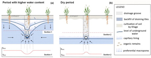
The method of identification and interpretation of DS features in RS image records is based on pedo-indicators (in the case of areas without cover, (a), autumn) and phyto-indicators (using vegetation cover, (b), spring). The key spatial associations that are assessed during visual interpretation and analysis of the drainage are the condition and variability of the soil (uncovered soil profile) and vegetation in the images at different times (i.e. spectral, tone/colour, brightness, and structural parameters).
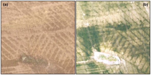
Figure 2. Typical visual features of functional DSs and permanently waterlogged locations on an aerial photo. (a) Bare arable land (light bands – 17.9.2014, 15 ground sample distance (GSD)), (b) cereal areas, winter wheat, emergence phenophase (dark lines – 15.5.2015, 12 GSD).
A wide range of RS image data and methods are applicable for identification of subsurface DS. With regard to the type of RS data (spectral band and their form), the most suitable are colour infrared images (CIR). DS are usually displayed with higher contrast and spatial sharpness in these analogue or digital images. Near infrared images have even better information value, due to their high sensitivity to the chlorophyll content in the plants (vegetation cover) and the water content in the soil (bare arable land). Nevertheless, panchromatic images (colour or black-and-white) provide similar information on DS spatial delineation, therefore they are also suitable for the identification of DS. Images from the visible spectrum (VIS), namely natural colour (RGB) aerial survey photographs, also provide better detectability in the context of natural colours of surveyed surfaces. These readily available images can more easily be used in routine agricultural, drainage and improvement practices.
The principles of DS interpretation from RS image data have been reported for many local studies and projects focused on land drainage measures and monitoring of large drained areas, especially uncovered soil surfaces prior to vegetation growth (e.g. CitationGoettelman, Grass, Millard, & Nixon, 1983; CitationKrusinger, 1971; CitationNaz, Ale, & Bowling, 2009; CitationNorthcott, Verma, & Cooke, 2000; CitationSpreckels, 1995; CitationSwiatkiewicz, 1994; CitationTetzlaff, Kuhr, & Wendland, 2009; CitationVerma, Cooke, & Wendte, 1996). Some thematic studies have been focused on using RS methods for the detection of soil moisture conditions and the principles of drainage functions (especially the analysis of local hydro-indication relationships, differences between drainage groove and surrounding, and DS manifestations – CitationLipský, 1990; CitationSvobodová, 1990; CitationTlapáková, Žaloudík, Pelíšek, & Kulhavý, 2014; CitationVinogradova, 1995). National studies have been aimed mainly at surveying the status and function of DS in specific agro-aerial surveys in the CR (CitationKulhavý et al., 2002, Citation2005, Citation2006; CitationTlapáková & Kulhavý, 2009; CitationTlapáková et al., 2008).
2.2. Study areas
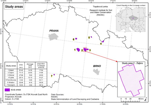
The potential of RS use for DS mapping was tested at seven localities in the CR (in east and south Bohemia) () representing both variable natural conditions and differing land management methods in the areas of interest. The basic characteristics of these localities are described in detail by CitationTlapáková, Žaloudík, Kulhavý, and Pelíšek (2015).
Figure 3. Location of the study areas.
All monitored localities have undergone repeated aerial surveys since 2012, both during and outside of the growing season. In parallel with image acquisition, where possible this was accompanied by field surveys, allowing better control and subsequent verification of the drainage phenomena identified in the images.
2.3. Primary RS image records
The data for interpretation of RS imagery used in DS identification were taken from experimental remote images of the study sites. They consisted of historical images acquired from a range of sources (airplanes, unmanned aerial system (RPAS), mobile masts), using various sensors (VIS, CIR, thermal) and output formats, and at differing spatial resolutions. The summary of image data for individual locations is given in .
Table 1. Overview of RS data acquired from a range of sources.
The purpose of multi-sensor data acquisition was to assess the conditions and criteria for correct identification and assessment of DS features in the RS images, to formulate the optimal approach (methodology) for the acquisition and analysis of remote data for DS recognition, and to evaluate their practical utility.
2.4. Preparation and processing of map and RS images for interpretation
In parallel with the acquisition of temporal images by RS, we collected the original design documentation of the DS in order to compare the existing information sources with the results of the mapping. DS designs differ in the manner, form and type of drawing, resulting in differing legibility and distinctness of the plots. Transformation into digital form was undertaken by scanning the designs at 300 DPI resolution, which is sufficient for correct georeferencing of the images and geographical information system (GIS) analysis.
Georeferencing is based on recent orthophotos, which are best used for identification of relatively recent DS (since the 1970s), because since that time land use has not markedly changed. With older DS, we faced the problem of landscape structure changes. Without old maps and old orthorectified aerial photos, most drainage designs cannot be properly fitted into the coordinate system. Because of their precise processing execution and with use of the corresponding historical background, design documents dating from the beginning of twentieth century allow very precise transformation into the coordinate system, and therefore DS localization in the terrain.
All images were orthorectified and served as initial material for DS identification. All analyses and specific processing of the remote and ground geodata were performed in a GIS environment. All information on DS was analysed and produced as thematic map libraries of DS (e.g. ).
Figure 4. Example map sheet from the libraries created for registration and classification of the identified DS (classification according to the type and extent of the identified manifestation). All map sheets are published in CitationTlapáková (2015).
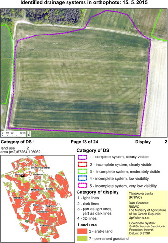
The DS visually identified in RS materials were first digitized on-screen as a polygon layer (with attributes describing the intensity, extent, and type of their appearance at particular recording dates). Further, we registered the type of vegetation cover and optionally the present specifics of the locality. To assess the quantitative parameters of the extent and topology of individual DS elements (collecting and conducting drains), at selected localities we vectorized the DS parts identified in RS recordings in the form of lines, which allowed us to establish the actual position of the network in the terrain.
2.5. Classification of DSs according to RS images
The following classes were used to assess the visual appearance of the DS in RS images:
According to the extent and distinctness of the visual appearance in the photos:
1 – complete system, well visible; 2 – incomplete system, well visible; 3 – incomplete system, less visible; 4 – incomplete system, limited visibility; 5 – incomplete system, very limited visibility.
According to the appearance in the images:
0 – not visible; 1 – light lines; 2 – dark lines; 3 – part of the system in light lines, part in dark lines; 4 – 3D manifestation.
According to land use type:
1 – arable land; 2 – permanent grassland.
In addition to this basic classification, we also differentiated between particular crops, phenological phases, vegetation density, and other characteristics in the drainage areas investigated in detail.
Examples of the DS classifications are shown in and Main Map.
2.6. Methodological approach to mapping subsurface drainage using RS
The classification of DS and their visual interpretation is based on distinct indirect evidence of functional systems, identifiable on the images by pedological and phytological indicators. These aspects are crucial in developing the correct methodology for DS identification using RS. The main points of the procedure are presented in .
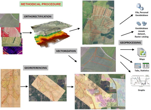
Figure 5. Methodological procedure (scheme of the main points of the applied approach).
3. Evaluation of the approach and its results
The results of the assessment and analyses of RS materials can be summarized as follows.
We distinguished two basic principles of visualization and identification of subsurface DS by means of RS. At the top level we used phyto-indication (1) and moisture differences (2) and at the sub-level we used phyto-indication in permanent grassland (1a) and arable land (1b). The main criteria and their weights are summarized in .
Table 2. Overview of the main criteria and conditions for visualization and identification of the DSs using RS.
The optimal conditions for targeted survey flights are:
The best conditions for identification by means of RS differ depending on the type of vegetative land cover, so three basic types must be distinguished: 1. permanent grasslands, 2. crop-covered arable land, and 3. vegetation-free land (CitationTlapáková et al., 2015):
Permanent grasslands – the best period for photographing is before the first cutting in Spring when there is higher and long-lasting soil water saturation ((a)). In contrast, the least convenient time for recording of permanent grasslands immediately follows grass cutting or pasture improvement and stripping ((b)).
Crop-covered arable land – an appropriate combination of the crop phenophase, precipitation amount, distribution and the timing during agricultural management, mainly fertilization, is suitable. Under these circumstances, arable land with cereal cover (approximately 37–75-day phenophase) enhances DS lines most effectively ((c)). Autumn, under similar natural and management conditions, but with a cash crop, rape represents quite a reliable type of cover for the surface visualization of DS ((d)).
Vegetation-free arable land – the most effective survey period seems to be in early Spring or during the Autumn, in optimal conditions of significant precipitation (at least 20 mm) with suitable temperature and moisture conditions and agricultural management (harvesting, tillage, harrowing, etc.). Visual evidence of the working DS is seen as higher tones of DS lines ((a)).
DS identification is typically more effective in permanent grassland areas, in images obtained at different periods with a wide range of conditions (in conditions favourable for more pronounced differentiation of grassland areas, without masking effects). Completed analyses allow us to note that the visual effects of drainage grooves in the vegetation can be recorded in almost all types of vegetation cover and crops, albeit with differing ‘quality’ and frequency. For instance, we have repeatedly identified drainage in large-row and tall crops (e.g. corn or rape in all growth phases). However, the type of vegetation cover is not the only decisive condition for a distinct display of the drainage grooves in the images, although it plays a very significant role.
Drainage mapping is influenced by seasonal agricultural activities (tillage and harrowing of arable land or fresh cutting of meadows, trampling and overgrazing of pastures by cattle), when the previously distinct structures of subsurface drains are partly or completely masked in the images.
The type of DS features captured in the images in natural colour (RGB) correlates with the features identified in colour infrared photos (CIR). So far, no differences in the basic drainage type, or its absence in one material and presence in the other, have been recorded in synchronously obtained images.
All test localities displayed the presence of a number of DS not registered in the documentation of hydro-amelioration systems. Older DS are often missing in the registry database, which confirms the necessity to revise this nationwide amelioration database. In many cases we also detected and confirmed differences between actual and plotted drainage lines in documentation, especially for DS identified by RS methods ().
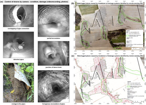
Analysis and field verification of the mapped localities with DS defects (soil probes, excavation, inspection by a pipe camera – (a)) showed that the condition and functionality of the drain, drainage line characteristics, building technology, and current soil condition (namely high cementation, density with minimum organic component content) represent key factors playing a significant role in the surface manifestations of DS (especially local soil waterlogging) and their practical mapping (see (b,c)).
A methodical approach and final results are presented as example thematic map sheets of DS on the Main Map (in supplement).
Figure 6. Permanent grassland before the first cutting (a) (3D lines – 7.6.2014) and after grass cutting (b) (light lines – 31.10.2014). Different types of visual manifestation of DSs in the crop (c) (7.7.2014) and rape cover (d) (26.11.2014).
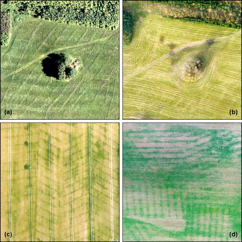
Figure 7. Map of the inaccurate registration of DS in selected part of the study area. Comparison of DS data sources: registry and documentation in the left part (a) and RS identification – plotted drain lines in the right part (b) and comparison of fitting the georeferenced DS building documentation to the aerial photo (c).
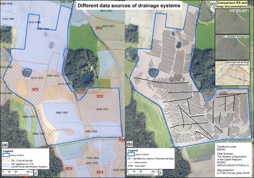
Figure 8. Mapping of localities with impaired DS functionality in the images, including DS verification by excavation and a mobile recording device inside the defective section (a). Visual evidence of impaired DS functionality (intensive soil waterlogged places including drains identified by RS methods (b)) compared to georeferenced original documentation (c).
4. Conclusions
The method of mapping subsurface DS using RS is an effective approach ensuring acquisition of up-to-date and precise digital documentation of the position and functionality of DS in the terrain. Nevertheless, the correct application of this method in various areas always requires adaptation to local requirements (e.g. cultivated crops, water regime, etc.). DS mapping using RS takes advantage of the spectral behaviour of the recorded ground surface, sensor properties and particular atmospheric conditions. The range of these features, however, is variable, and so the use of automated classification is of limited success.
Based on our experiments and analyses we can say that a distinct display of functional drainage lines in images can be recorded both in the vegetated period and outside it because of visual differences in soil surface or vegetation.
The primary type of DS feature captured in panchromatic images in natural colours correlates with the type of DS feature identified in infrared photos. However, there are some differences in the distinctness of the evidence. This fits the assumption that in suitable positional, agricultural and meteorological conditions, subsurface drainage can be identified with the same success in different image materials and with the use of different detection methods (both above- and underground). In contrast, in unsuitable conditions, none of the recording methods showed a markedly better success than others.
As well as evaluating DS features, we also evaluated the sharpness of the visible drainage lines compared to the surrounding area (towards the inter-drain space). With a typical ‘light display’ (corresponding to gradual differentiation of arable land desiccation after precipitation), the entire range recorded so far was represented by an unfocused and relatively large line (1 to 3+ m wide). In contrast, most lines identified in the characteristic ‘dark display’ in the vegetation cover were better delineated, appearing more focused, with more contrast, and were also narrower (ca 30–40 cm in width, better corresponding to the drainage groove width).
The sharpness and contrast of the displayed drainage lines is not a limitation to the use of our method of DS identification, but may limit the precision of their subsequent terrain layout (e.g. during repairs, construction plans, etc.). However, even when wider drainage lines were identified in the images, a satisfactory level of precision in their layout was achieved and verified in practice.
Given that most identified DS, during survey flights 2012–2015, are classified into the limited category of ‘incomplete systems’ (categories 2–5), we can suppose that the best category (complete system in high quality drain delineation) can rarely be reached. The results show that only approximately 5% of identified DS belong to the category with complete and well visible DS. The main reason for this finding is connected to the age of systems that were built between 1890 and 1990, and the lack of data and information on their actual functionality and condition. In these circumstances, the DS location is best verified by direct excavation of the drains in the field, which can only be performed locally, and not to the same extent comparable with aerial imaging.
Achievement success of DS identification in each of the study sites varies from 60% to 91%, depending on concrete meteorological and spatial conditions during survey flights. The detailed survey of the selected areas has thus brought essential insights.
The optimum method for practical DS mapping is a combination of standard large-scale aerial imaging (images and orthophotos) and complementary recording of smaller land parcels by UAS tools. Combining images with information on actual conditions of the soil cover and recorded area directly in the field improves results. In addition, benefit may also be gained by using a detailed digital surface model (e.g. to assess the drain slope and construct the DS topology in localities with missing design documentation) and potentially more frequent imaging.
Successful DS mapping can only be achieved using a complex approach, taking account of the changing conditions in agriculture. In order to account for different local agro-technical measures applied in various areas, the method must be further developed in order to reflect the local conditions.
Software
ESRI ArcGIS 10.2 was used for map production, including creating geodatabases, editing, georeferencing, image, DEM and overlay analysis, and the preparation of final layouts. Geomatica 10.2 was used for orthorectification of aerial photographs, multispectral data editing and postprocessing.
Subsurface drainage systems in the Czech Republic.pdf
Download PDF (32.5 MB)Disclosure statement
No potential conflict of interest was reported by the authors.
Additional information
Funding
Related Research Data
References
- Goettelman, R. C., Grass, L. B., Millard, J. P., & Nixon, P. R. (1983). Comparison of multispectral remote-sensing techniques for monitoring subsurface drainage conditions. NASA Technical Memorandum No. 84317, 16 pp.
- Krusinger, A. E. (1971). Location of drainage tile using aerial photography (MS thesis). Ohio State University, Columbus, OH, 143 pp. + maps.
- Kulhavý, Z., Žaloudík, J., Tlapáková, L., Burešová, Z., Eichler, J., & Čmelík, M. (2005). Identification of subsurface drainage systems by air photographs. Proceedings of 21st European regional conference ‘Integrated Land and Water Management: Towards Sustainable Rural Development’ (Topic 3 – Irrigation and drainage), ICID, Frankfurt, 4 pp. (poster).
- Kulhavý, Z., Soukup, M., Doležal, F., & Čmelík, M. (2006). Final report of research project rationalization of the use, maintenance and repairs of drainage systems. NAZV No. QF 3095. Prague: RISWC, 42 pp. (in Czech).
- Kulhavý, Z., Hodovský, J., Žaloudík, J., Kremláček, I., Navrátil, A., Doležal, F., … Soukup, M. (2002). Design and utilization of a territorial information system of hydromelioration constructions. Final report of project design and utilization of a territorial information system of hydromelioration constructions, NAZV No. QC1294. RISWC Prague, AWMA, IEL ASCR, 23 pp. (in Czech).
- Lipský, Z. (1990). Utilization of aerial images for monitoring of agricultural land waterlogging. Proceeding of the conference RS utilization in water management, DT ČSVTS, Prague, pp. 81–90 (in Czech).
- Naz, B. S., Ale, S., & Bowling, L. C. (2009). Detecting subsurface drainage systems and estimating drain spacing in intensively managed agricultural landscapes. Agricultural Water Management, 96, 627–637. doi:10.1016/j.agwat.2008.10.002
- Northcott, W. J., Verma, A. K., & Cooke, R. A. (2000, July 9–12). Mapping subsurface drainage systems using remote sensing and GIS. ASAE annual international meeting, Milwaukee, WI, pp. 1–10.
- Spreckels, V. (1995). Erfassung und Auswertung von Dränungen in landwirtschaftlichen Nutzflächen auf der Basis von Fernerkundungsdaten und geographischen Informationssystemen. Diplomarbeit. Hannover: Leibnitz Universität, 120 pp. (in German).
- Svobodová, D. (1990). Background and technical solution of drainage. Research report of VE04 project P 06-329-813-02 technique, technology and renovation of drainage. Prague: Research Institute for Fertilization of Agricultural Land, 54 pp. (in Czech).
- Swiatkiewicz, A. (1994). Remote sensing of drainage networks using aerial images (dissertation). Rozprawy, No. 242. Zeszyty Naukowe Akademii Rolniczej we Wroclawiu, Wroclaw, 112 pp. (in Polish).
- Tetzlaff, B., Kuhr, P., & Wendland, F. (2009). A new method for creating maps of artificially drained areas in large river basins based on aerial photographs and geodata. Irrigation and Drainage, 58, 569–585. doi:10.1002/ird.426
- Tlapáková, L. (2015). The maps of drainage systems identified by means of remote sensing. Specialised map. Certification Nr. 2/2016-SPU/O (in Czech).
- Tlapáková, L., & Kulhavý, Z. (2009). Utilization of RS material in assembly of the atlas of drainage systems. Vodní Hospodářství (Water Management), 59(6), 221–223 (in Czech).
- Tlapáková, L., Kulhavý, Z., & Burešová, Z. (2008). Atlas of drainage systems in the district of Chrudim with delineation of areas identified by remote sensing tools. RISWC, 74 pp. (in Czech).
- Tlapáková, L., Žaloudík, J., Kulhavý, Z., & Pelíšek, I. (2015). Use of remote sensing for identification and description of subsurface drainage systém condition. Acta Universitatis Agriculturae et Silviculturae Mendelianae Brunensis, 63(5), 1587–1599. doi:10.11118/actaun201563051587
- Tlapáková, L., Žaloudík, J., Pelíšek, I., & Kulhavý, Z. (2014). Identification of drainage systems using the remote sensing tools (introduction). Vodní Hospodářství (Water Management), 64(3), 8–14 (in Czech).
- Verma, A. K., Cooke, R. A., & Wendte, L. (1996, September 22–26). Mapping subsurface drainage systems with color infrared aerial photographs. AWRA symposium on GIS and water resources, Ft. Lauderdale, FL.
- Vinogradova, N. V. (1995). Preparation of methods for assessment of drainage system conditions after aerial imaging with use of spectral soil characteristics (dissertation). Institute of Hydrotechnique and Soil Recultivation of A. N. Kostyakov, Moscow (in Russian).