
ABSTRACT
By using images acquired by the Mercury dual imaging system (MDIS) on-board the MESSENGER spacecraft during 2008–2015 and available DTMs, a new 1:3,000,000-scale geological map of the Shakespeare quadrangle of Mercury has been compiled. The quadrangle is located between latitudes 22.5°–65.0°N and longitudes 270.0°–180.0°E and covers an area of about 5 million km2. The mapping was based on photo-interpretation performed on a reference monochromatic basemap of reflectance at 166 m/pixel resolution. The geological features were digitized within a geographic information system with a variable mapping scale between 1:300,000 and 1:600,000. This quadrangle is characterized by the occurrence of three main types of plains materials and four basin materials (pertaining to the Caloris basin), whose geologic boundaries have been here redefined compared to the previous map of the quadrangle. The stratigraphic relationships between the craters were based on three main degradation morphologies. Furthermore, previously unmapped tectonic landforms were detected and interpreted as thrusts or wrinkle ridges.
1. Introduction
Mercury’s surface was photographed for the first time (1974) by the probe Mariner 10 (M10), launched by the National Aeronautics and Space Administration (NASA). A goal of the M10 mission was the geologic mapping of Mercury’s surface (CitationHolt, 1978) that was divided into 15 quadrangles by the International Astronomical Union. The M10 remotely sensed images (best resolution at 1.0–1.5 km, see CitationHead et al., 2007; CitationSpudis & Guest, 1988; CitationStrom, 1987) revealed an intensely cratered surface attributed to the ‘late heavy bombardment’ event (see CitationHead et al., 2007; CitationStrom, Trask, & Guest, 1975) which is thought to have affected the inner solar system about 4 billion years ago (CitationFassett & Minton, 2013). Tectonic landforms, such as lobate scarps, high-relief ridges and wrinkle ridges, were recognized (e.g. CitationMelosh & Dzurisin, 1978; CitationMelosh & McKinnon, 1988; CitationPechmann & Melosh, 1979; CitationSolomon, 1977; CitationStrom et al., 1975; CitationWatters & Nimmo, 2010) and several ‘terrain units’ (see CitationTrask & Guest, 1975) were distinguished according to their morphologies and textures. With the first geological maps of some quadrangles at 1:5,000,000-scale, published in the early 1980s by the United States Geological Survey (USGS), the former ‘terrain units’ were renamed as ‘geologic provinces’ (see CitationMcCauley & Wilhelms, 1971) and defined as: plain materials, basin materials and crater materials. The units of plain materials were distinguished as smooth, intermediate and intercrater plains materials (CitationDe Hon, Scott, & Underwood, 1981; CitationGuest & Greeley, 1983; CitationKing & Scott, 1990; CitationMcGill & King, 1983; CitationSchaber & McCauley, 1980; CitationTrask & Dzurisin, 1984). Basin materials with peculiar morphologies were distinguished in H03 and were associated with the Caloris basin (i.e. Caloris Group, see CitationMcCauley, Guest, Schaber, Trask, & Greeley, 1981), the largest impact crater on Mercury (D ∼1550 km, see CitationBuczkowski, Denevi, Ernst, Fassett, & Byrne, 2015; CitationKerber et al., 2009). In addition to this, craters were mapped according to their degree of degradation and grouped into five classes from the oldest c1 to the youngest c5 (CitationMcCauley et al., 1981).
During the 2008–2015 period, a new data set of images was acquired by the Mercury dual imaging system (MDIS) instrument within the MESSENGER (MErcury Surface, Space ENvironment, GEochemistry, and Ranging) NASA mission (CitationSolomon et al., 2001, Citation2008).
By using MDIS basemaps, a new 1:3,000,000-scale geological map of the H03 Shakespeare quadrangle (previously mapped at 1:5,000,000-scale by CitationGuest & Greeley, 1983) has been compiled, following criteria adopted for the 1:3M geologic mapping of the Raditladi (CitationMancinelli, Minelli, Pauselli, & Costanzo, 2016) and Victoria (CitationGalluzzi et al., 2016) quadrangles. The H03 quadrangle is located at middle-latitude of the northern hemisphere of Mercury and covers an area that represents 6.5% of the total planet surface. The new map represents the first complete cartographic product of the Shakespeare quadrangle at this scale. The most evident novelty, with respect to the previous published map of the quadrangle (CitationGuest & Greeley, 1983), is the adoption of a different crater classification which solves some stratigraphic inconsistences of the previous five-class classification. Moreover, a better correlation between morphology and geological boundaries led to a significant redefinition of the spatial distribution of the intercrater and intermediate plain materials.
2. Data and methods
2.1. Map data
Mapping was based on photo-geologic interpretation of a 166-m/pixel resolution monochrome basemap of the Shakespeare quadrangle ((a)), released by the NASA’s planetary data system. This basemap, derived from the mosaicking of four BDR (map projected Basemap reduced Data Record) tiles, represents the MDIS product with the highest resolution available to date. To complete mapping near the quadrangle limits, nine BDR tiles from adjacent quadrangles were mosaicked with the reference basemap to produce 5° overlap at its boundaries ((b)). A suite of a lower resolution basemaps () were also consulted because their different lighting conditions have facilitated the mapping. Basemaps were used in combination with available topographic data (two DTMs) produced from MESSENGER Mercury Laser Altimeter (MLA) data and data sets by CitationZuber et al., 2012. Topography was useful in sectors with non-optimal lighting geometry (e.g. solar incidence angles <30° or >80°) where morphologies are either masked by a flat lighting conditions or long shadows. One DTM covers only the northern part of the quadrangle ((a)) with a cell-size resolution of 500 m. The other DTM covers the entire quadrangle with a 665-m resolution ((b)), although its quality decreases southwards due to the increase towards the equator of the spacing between the MLA tracks (up to ∼100 km at 22.5°N). Map data were georeferenced adopting the datum used in the data sets released by the MESSENGER team, in which Mercury’s radius (2439.7 km) is approximated to 2440.0 km. The most suitable projection at middle-latitudes is the Lambert conformal conic (LCC, see CitationDavies, Dwornik, Gault, & Strom, 1978), as it reduces area distortion. The LCC conventionally uses two standard parallels (30°N and 58°N) fixed at a distance of 1/6 and 5/6 of the latitudinal range (CitationDeetz & Adams, 1945). The scale of features is accurate along the standard parallels, slightly smaller between them and slightly larger beyond them.
Figure 1. (a) BDR basemap at ∼166 m/pixel resolution of the H03 quadrangle displayed in Lambert Conformal Conic (LCC) projection with standard parallels at 30°N and 58°N. (b) BDR tiles (displayed in Equirectangular projection) mosaicked to obtain the reference basemap with 5° overlap (red box) at its boundaries. The quadrangles are identified by their code (e.g. H-03, where H is the abbreviation for Hermes), their official name derives from topographic features (e.g. Shakespeare) and their former name (e.g. Caduceata) based on albedo features. The value (6.5%) represents the percentage of area covered by the quadrangle.
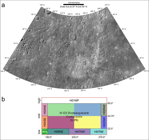
Figure 2. MLA topography available for the H03 quadrangle (CitationZuber et al., 2012). (a) MLA north pole coverage. (b) MLA global coverage.
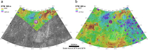
Table 1. List of used basemaps.
2.2. Mapping criteria and geodatabase
The geological features were digitized using Esri ArcGIS where a spatial geodatabase was structured following the USGS guidelines (CitationTanaka, Skinner, & Hare, 2011). The geodatabase includes three feature classes containing polylines (linear features and geologic contacts) and polygons (surface features) as shown in .
Table 2. Types of mapped features (right column) and the class to which they belong (left column).
Craters were distinguished into those with a diameter between 10 and 20 km (‘small’) and craters with D > 20 km (‘major’). In agreement with other authors (see CitationFassett, Kadish, Head, Solomon, & Strom, 2011), we chosen D > 20 km to assure that the observed population consists of primary impact craters. On Mercury, secondary craters can have diameters up to, or greater than, 10 km and locally even up to 20 km (CitationStrom et al., 2011; CitationStrom, Chapman, Merline, Solomon, & Head, 2008). For small craters only rim crests were mapped, whereas major craters and the related materials were grouped into degradation classes. Instead of the previously used five classes of degradation (M10 c1–c5; see CitationMcCauley et al., 1981, recently reviewed by CitationKinczyk, Prockter, Chapman, & Susorney, 2016), we used a simplified classification with three degradation classes (c1–c3; see CitationGalluzzi et al., 2016) in which craters and related materials are distinguished according to their overlapping relationships. Crater morphology is primarily controlled by their dimensions and subsequent impacts, thereby smaller craters are more prone to be degraded than larger ones; this might lead to erroneous interpretations of stratigraphic age, since smaller craters can appear older than they are (see CitationMcCauley et al., 1981). Moreover, with the previous classification, degraded craters sometimes superimpose less degraded craters, mostly in heavily cratered terrain. The use of only three classes solves these stratigraphic inconsistencies, because reduces the error in assigning relative ages, privileging stratigraphic order rather than morphological appearance. The new classification groups the youngest fresh craters (c3 – well-preserved craters) and the oldest heavily degraded craters (c1 – very degraded craters older) into two end-member classes, with the remainder into a class (c2 – moderately degraded craters) which encompasses all the intermediate morphologies, considered stratigraphically coeval ((a–c)). Rim crests of large craters, still visible but covered by other units or intensely degraded, were mapped as ‘buried or subdued crater rim’.
Figure 3. Type-localities for the three crater classes found within the H03 quadrangle. (a) ‘Ahmad Baba’ crater (232°E, 58°N) c3 class. (b) ‘Whitman’ crater (249°E, 41°N) c2 class. (c) Unknown crater (239°E, 47°N) c1 class.
Based on the dominant contractional nature of Mercury’s tectonics (CitationByrne et al., 2014; CitationDi Achille et al., 2012; CitationMelosh & Dzurisin, 1978; CitationSpudis & Guest, 1988), the morpho-structures such as arcuate scarps and lineament systems are commonly interpreted as thrust or high-angle reverse faults (CitationDzurisin, 1978; CitationStrom et al., 1975; CitationWatters & Nimmo, 2010; CitationWatters, Robinson, & Cook, 1998). The structures were here classified as thrusts and mapped as ‘certain’ or ‘uncertain’, whether or not the break in slope was clear and sharp, respectively ((a,b)). The structures showing a less prominent ridge within smooth plains and basins were generally mapped as wrinkle ridges.
Figure 4. (a) Thrust structures that crosscut a c1 crater (D ∼49 km; centred at 230°E, 29°N). (b) Thrusts were mapped as certain where the break in slope is clear and sharp and as uncertain where the break in slope is less clear and evident.
On the base of rules similar to the ones adopted for structures, the geologic contacts were mapped as ‘certain’ where they are clear and sharp, or ‘approximate’ where they are uncertain or gradational. Considering the uneven resolution of the basemap and the final output, the contacts were drawn at a scale varying between 1:300,000 and 1:600,000 according to the USGS guidelines (see CitationTanaka et al., 2011). Other geomorphological elements such as ‘hollows’ (shallow depressions at sub-kilometre scale, typically surrounded by bright deposits and generally occurring in impact craters; see CitationBlewett et al., 2011; CitationThomas, Rothery, Conway, & Anand, 2014), crater chains and clusters, light coloured ejecta and bright deposits have also been mapped when their width is >3 km. The geologic units were distinguished according to their morphological aspects and following definitions of previous authors (e.g. CitationGuest & Greeley, 1983; CitationSpudis & Guest, 1988).
3. Geological background
Spudis (1985; see review by CitationSpudis & Guest, 1988) defined a Mercurian time-stratigraphic system based on the M10 geologic mapping (CitationHolt, 1978) and the definition and subdivision of the Caloris Group by CitationMcCauley et al. (1981). The Caloris Group identifies a complex geologic landform, recognized for the first time by CitationTrask and Guest (1975), which has been associated with the impact region of the Caloris basin. The first geological map of the Shakespeare quadrangle was compiled by CitationGuest and Greeley (1983) using the Caloris Group as a chronostratigraphic marker. From the basin rim outward, several units in CitationGuest and Greeley (1983) were distinguished as follows: Caloris Montes Formation, Nervo Formation, Van Eyck Formation and Odin Formation (see CitationGuest & Greeley, 1983; CitationMcCauley et al., 1981). The Caloris Montes Formation consists of a prominent massif ring composed of individual blocks surrounding the Caloris basin and was interpreted as uplifted bedrock (CitationTrask & Guest, 1975). The Nervo Formation identifies a unit filling depressions between these mountains and was interpreted as a mixture of fallback material and impact melt (CitationSpudis & Guest, 1988). The Van Eyck Formation exhibits two main facies: lineated facies (see CitationTrask & Guest, 1975), formed by a sub-radial pattern of long ridges and grooves well-preserved northeast of the basin, and secondary crater facies (see CitationSchaber & McCauley, 1980) mapped in the south of the basin along the Tolstoj quadrangle. The Odin Formation was described as hummocky plains characterized by closely spaced gentle hills that extend up to many hundreds of kilometres from the Caloris Montes (CitationTrask & Guest, 1975). The Van Eyck and Odin formations were considered ejecta of Caloris (CitationFassett et al., 2009; CitationGuest & Greeley, 1983; CitationMcCauley et al., 1981; CitationSchaber & McCauley, 1980; CitationSpudis & Guest, 1988).
The intercrater plain materials display as hummocky texture surface resulting from a high density of superposed impact craters, generally D < 10 km (CitationGuest & Greeley, 1983; CitationSpudis & Guest, 1988). Even though their origin remains debated, they were interpreted as the oldest unit on the planet (CitationGuest & Greeley, 1983; CitationHead et al., 2007; CitationSpudis & Guest, 1988; CitationWhitten, Head, Denevi, & Solomon, 2014). The smooth plain materials were described as flat to gently rolling plains with numerous wrinkle ridges (CitationSpudis & Guest, 1988; CitationTrask & Guest, 1975) showing a low density of large and degraded craters. These plains represent the youngest unit (CitationDenevi et al., 2013; CitationWhitten et al., 2014) and is thought to have a volcanic origin (CitationDenevi et al., 2013; CitationFassett et al., 2009; CitationHead et al., 2009; CitationSpudis & Guest, 1988; CitationStrom et al., 1975; CitationTrask & Guest, 1975; CitationTrask & Strom, 1976; CitationWhitten et al., 2014). The intermediate plain materials were described as flat to rolling plains with fewer superposed craters than intercrater plain materials (CitationGuest & Greeley, 1983; CitationSchaber & McCauley, 1980). They were interpreted as volcanic materials older than smooth plain materials or as shock-melt materials (CitationGuest & Greeley, 1983; CitationSpudis & Guest, 1988). Recently, some authors have considered this unit representative of intercrater areas partly flooded by the younger smooth plain materials (CitationDenevi et al., 2013).
Three main types of landforms associated with crustal shortening are recognized on Mercury: lobate scarps, high-relief ridges and wrinkle ridges (CitationDzurisin, 1978; CitationMelosh & McKinnon, 1988; CitationSpudis & Guest, 1988; CitationStrom et al., 1975; CitationWatters, 1988; CitationWatters & Nimmo, 2010). The lobate scarps are the most represented and prominent tectonic features and consist of sinuous or arcuate scarps with scalloped edges (CitationSpudis & Guest, 1988; CitationStrom et al., 1975). They have been interpreted as thrust faults that propagate through all plains materials (CitationMassironi, Byrne, & Van Der Bogert, 2015; CitationStrom et al., 1975; CitationWatters & Nimmo, 2010). The high-relief ridges are prominent landforms generally with no evidence of significant offset, interpreted as a surface expression of high-angle reverse faults to transpressive faulting (CitationDzurisin, 1978; CitationMassironi et al., 2015; CitationMelosh & McKinnon, 1988; CitationWatters & Nimmo, 2010). They can merge laterally into lobate scarps suggesting a related origin (CitationByrne et al., 2014; CitationWatters & Nimmo, 2010; CitationWatters, Cook, & Robinson, 2001). The wrinkle ridges are landforms related to folding and thrust faulting that show a broad low-relief arch with superimposed ridges and mainly occur in the smooth plains and basin interior plains (CitationKorteniemi, Walsh, & Hughes, 2015; CitationWatters, 1988; CitationWatters & Nimmo, 2010). Further, landforms that express extensional deformation were recognized within some large basins like Caloris (e.g. Rembrandt, Rachmaninoff, Raditladi, see CitationMurchie et al., 2008; CitationProckter et al., 2010; CitationSolomon et al., 2008; CitationWatters et al., 2009c), in which a complex network of linear and sinuous narrow troughs occurs (CitationBlair et al., 2013; CitationKlimczak et al., 2013; CitationMelosh & McKinnon, 1988; CitationStrom et al., 1975; CitationWatters, Nimmo, & Robinson, 2005). Several groups of troughs were also observed on smooth plains at high northern latitudes and surrounding Caloris (CitationHead et al., 2011; CitationKlimczak et al., 2012; CitationWatters et al., 2012).
4. Shakespeare quadrangle (H03) geologic map
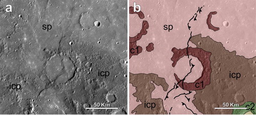
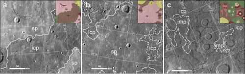
The geological map of the Shakespeare quadrangle (H03) shows the distribution of the units pertaining to plain materials, basin materials and crater materials. The intercrater plain (ICP) and smooth plain (SP) materials are the main plain materials occurring in the quadrangle, whereas the intermediate plain (IMP) materials occur only as small patches, mostly in the eastern sector of the map ((a–c)).The basin materials are associated with the Caloris basin (centred at 30.0°N, 165.0°E, Raditladi quadrangle), the most prominent geomorphological feature of the quadrangle, and are distinguished according to four formations termed with official names (see CitationMcCauley et al., 1981). Crater-related materials include central peaks, peak rings, floors and ejecta.
Figure 5. The range of plain morphologies within the H03 quadrangle. (a) Comparison of textures surface between SP and ICP in the central sector of the quadrangle, highlighted by clear albedo contrasts. (b) Example of SP with slightly corrugated surface texture with respect to the flatter shown in (a). (c) Example of ICP in the eastern sector of the quadrangle and IMP that occur as small patches.
4.1. Mapped units
4.1.1. Plain materials
The oldest unit in the quadrangle is represented by the ICP materials that are interpreted as remnants of volcanic flows (CitationDenevi et al., 2013). The ICPs are rolling plains with hummocky surface texture generated by the high density of superposed craters. They mainly occur in the eastern sector of the map between and around large c1 and c2 craters. In the central sector of the quadrangle they are surrounded by SPs with sharp contacts, while westward, in the region of Caloris, they are almost absent. The IMP materials display smoothed morphologies and poorly defined boundaries, with more overlapped craters than the SPs. They occur as patches among the ICP in the eastern area of H03 and their outcropping area is less extensive than that mapped in the previous 1:5M map of the quadrangle. The SP materials appear from flat to gently rolling and poorly cratered plains extensively outcropping in the northeast of Caloris (Suisei Planitia) and in the central (Sobkou Planitia) and southern (Budh Planitia) sectors of the quadrangle. In the eastern area, they occur as small patches mainly around the Scarlatti crater (259.5°E, 40.5°N) and within large old basins. They show sharp contacts with adjacent units (e.g. ICP) but become gradational with the Odin Formation westward. In agreement with previous authors (CitationGuest & Greeley, 1983; CitationSchaber & McCauley, 1980), the SP within Caloris (SPc) have been distinguished because they represent a fill unit that obscures the original floor of the basin (see CitationMcCauley et al., 1981) and are affected by extensional deformation. They were interpreted as thick impact-melt sheets (CitationGuest & Greeley, 1983) or as volcanic materials emplaced after the basin formation (CitationGuest & Greeley, 1983; CitationMurchie et al., 2008). In agreement with CitationDenevi et al. (2013) and CitationOstrach et al. (2015), we have also distinguished the northern SP (SPn), confined to the north polar region, because they show an age slightly younger than the other SP. Only a small portion of SPn occurs in the NE corner of the map. The SP and SPn large expanses are thought to be volcanic (CitationDenevi et al., 2013).
4.1.2. Basin materials – Caloris Group
As formalized by CitationMcCauley et al. (1981), the basin materials in the H03 quadrangle are associated with the Caloris Group.
The Caloris Montes Formation (CMF) constitutes a prominent mountain ring surrounding the Caloris basin, locally interrupted towards the southeast, from about 26.0°N to 24.0°N and 184.0°E. This unit forms the rim crest of the basin and it was interpreted as uplifted bedrock (CitationTrask & Guest, 1975).
The Nervo Formation (NF) is a unit occurring in depressions between CMF massifs showing more rugged morphology than SP. The NF lies topographically above the SPc and the SP surrounding the Caloris basin and its boundaries are not easily recognizable. It was interpreted by CitationSpudis and Guest (1988) as fallback material mixed with impact melt.
The Van Eyck Formation (VEF), named after the homonymous crater (43.2°N, 201.8°E), is only represented by the lineated facies. It consists of long ridges, generally sub-radial to Caloris, and grooves sharply bounded by the adjacent Odin Formation (OF) and SP. In the quadrangle, the VEF extends for about 1000 km eastward from the outer edge of CMF and NF and it was interpreted as ejecta from Caloris (CitationBuczkowski et al., 2015; CitationFassett et al., 2009).
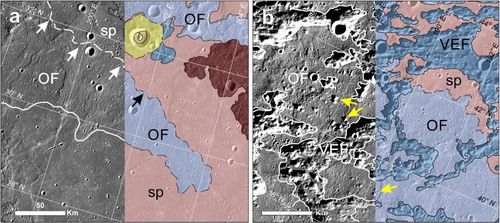
The OF extends for about 850 km outward from the inner edge of the basin and shows two distinct morphological characteristics. In the east sector of the Odin Planitia (24.0°N, 195.0°E) and slightly north of it (32.0°N, and between 190.0°E and 205.0°E), it is constituted by low and tightly spaced hills ((a)), while NE of Caloris it appears as a knobby plain among the VEF (40.0°N, 190.0°E). The knobs, interpreted as ejecta blocks of Caloris (CitationFassett et al., 2009; CitationSchaber & McCauley, 1980), occur within fine texture material (defined ‘bottom material’ by CitationGuest & Greeley, 1983) that has identical surface characteristics to that of the SP ((b)). The two morphologies are not easily discernible from each other since they are often compenetrated and their boundaries are difficult to trace. The OF shows gradational boundaries with the adjoining SP.
Figure 6. (a) Low hills of the OF concentric to the rim of Caloris. In some places the boundary with the adjacent SP is gradational (approximate contact marked with dashed line indicated by arrows). (b) OF – knobby facies constituted by small blocks (yellow arrows), interpreted as Caloris ejecta, surrounded by smoothed material. The OF occurs between the ridges and grooves of the VEF.
4.1.3. Crater materials
Central peaks, peak rings and ejecta follow the designation of the crater class to which they belong, while crater floors are distinct according to their morphologies and crater density. To assess crater class, rim sharpness and ejecta texture are considered.
Fresh carters with continuous and sharp rims and associated well-preserved ejecta, central peaks and peak rings have been classified as c3. They usually display ejecta blankets, bright ray systems and dark or bright halos. The largest may also display radial secondary craters (i.e. crater chains).
Craters have been classified as c2 have generally continuous rims but are degraded or slightly subdued. Central peaks and peak rings are still recognizable but often superposed by other craters. For this crater class, the distal ejecta are not easily distinguishable, except for the largest craters.
Craters with a strongly degraded rim crest, often discontinuous and just exposed, have been mapped as c1. The rims usually rise above the ICP or as relicts among the SP. Central peaks are seldom recognizable and the ejecta blankets are barely distinguishable from the surrounding ICP. For these craters, secondary crater chains are generally unrecognizable.
Rough and moderately or intensely cratered materials on craters floor have been mapped as hummocky floor materials (cfh). Generally, they correspond to crater wall debris in c3 or to very degraded floors in c2 and c1 craters. Floors that are smooth and flat have been mapped as smooth floor materials (cfs) and form c3 and c2 craters floor or occur as resurfaced floors inside large c1 craters.
4.2. Relative age estimate and overall stratigraphy
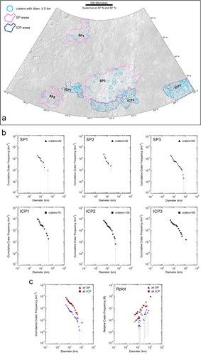
The relative ages have been determined for the SP and ICP by using the method described in CitationCrater Analysis Techniques Working Group (1979) and CitationNeukum (1983). The units’ relative ages are expressed by a cumulative size-frequency distribution diagram (CSFD) obtained by using the crater counting technique. We have considered three sample areas for each unit ((a)) where the SP and ICP have a good areal extent and representative crater density, but excluded areas of secondary crater clusters. The counted craters have D ≥ 5 km and do not include crater chains. In accordance with other authors (see CitationDenevi et al., 2013), the plotted data ((b)) confirm a younger age of the SP with respect to the ICP ((c)).
Figure 7. (a) Six study areas (three for each unit) considered to determine the relative age of the SP and ICP units. (b) CSFDs for SP and ICP. (c) Comparison between the CSFD and the Relative-SFD (Rplot) diagrams of the two units.
The mapping process and the above considerations have allowed reconstruction of a relative stratigraphic scheme of the mapped units in the quadrangle (see ‘correlation of map units’ in the Main Map). In agreement with previous authors, we consider the ICP earlier than the end of the Late Heavy Bombardment (CitationTrask & Guest, 1975), confirming that it is the oldest unit in the quadrangle (see CitationWhitten et al., 2014). Based on previous work, the IMP are considered slightly younger than the ICP (CitationWhitten et al., 2014). Several authors estimated an age of 3.7–3.9 Ga of the SP (CitationDenevi et al., 2013; CitationFassett et al., 2009; CitationHead et al., 2011; CitationStrom et al., 2008; Citation2011), that coincides with our estimate based on the crater density distribution. The units of the Caloris Group are considered coeval among them and slightly older than SPc. For SPn's age has been considered the minimum age limit of the SP, setted to 3.69 Ga by CitationOstrach et al. (2015).
Crater materials are constrained by the superposition of younger craters to older. The relative constraints with other geologic units are given by the observation that the c1 craters occur as remnant rims within the SP and the c2 overlap the SP in the central sector of the quadrangle, but they are rare westwards, above the units of the Caloris Group.
4.3. Structural features
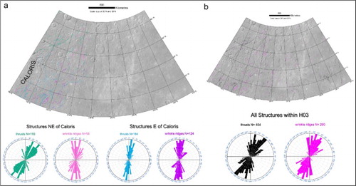
Thrusts and wrinkle ridges mainly occur within the OF and SP unit in the western sector of the quadrangle. Orientation analyses show that the main trend of thrusts is aligned ∼N40°E, in the area to the NE of Caloris, whereas the wrinkle ridges are mainly aligned ∼N10°E. To the E of Caloris, the azimuth-frequency diagram shows a preferential NNE–SSW trend for both kinds of structures ((a)). In the eastern sector of the quadrangle fewer structures were detected due to a higher surface roughness that made their identification more difficult. Statistical analyses of all structures within the H03 quadrangle show that the main trend is represented by the N40°–45°E and N15°–20° E azimuthal domain for thrusts and wrinkle ridges, respectively ((b)).
Figure 8. (a) Distribution of the mapped structures surrounding the Caloris basin and relative azimuth-frequency diagrams showing the main trend for thrusts and wrinkle ridges, respectively. These structures have been gathered according to two preferential orientations: in the NE, NE–SW trending thrusts appear to form a radial pattern with respect to the Caloris basin geometry, whereas the wrinkle ridges are mainly oriented between N10°E and N15°E. To the East of the basin, the NNE–SSW oriented thrusts and wrinkle ridges appear to have a non-radial geometry with respect to Caloris. (b) Global distribution of all mapped structures in the H03 quadrangle and relative azimuth-frequency diagrams that show N40°–45°E and N15°–20°E azimuthal domains for thrusts and wrinkle ridges, respectively.
5. Conclusions
The MESSENGER images have allowed production of a more detailed 1:3M cartographic product of the Shakespeare quadrangle with respect to the previous 1:5M scale map (CitationGuest & Greeley, 1983), based on Mariner 10 images. The craters with D > 20 km were grouped into three degradation classes (c1–c3) by integrating morphology, craters size and stratigraphy, which allowed us to avoid the contradictions of the previous classification (c1–c5). The c3 craters are the most abundant and widespread over the whole quadrangle, whereas the c2 and c1 craters mainly occur in the eastern sector of the quadrangle, in heavily cratered terrain.
The western sector of the mapped area is occupied by a portion of the Caloris basin and associated ejecta which are embayed and partly covered by SPs. Caloris ejecta appear as a discontinuous annulus around the basin and are widespread from its rim up to 215.0°E and between 61.0°N and 22.5°N outwards.
The SPs also characterize the central sector of the quadrangle, where they are overlapped by c2 and c3 craters. Some of these c3 craters show well-developed bright rays that extend up to ∼850 km. The ICPs dominate in the eastern part of the quadrangle, in which also some patches of IMPs occur. The detected morpho-structures, that mostly deform the units around the Caloris basin, have contributed to an assessment of the deformation pattern of the quadrangle and will contribute to better evaluation of past stress states of the planet. This geologic map fills the gap between the two 1:3,000,000-scale maps by CitationMancinelli et al. (2016) and CitationGalluzzi et al. (2016) and can be considered an important support to future advanced local studies and target selection for the scheduled ESA-JAXA BepiColombo mission to Mercury.
Software
This map was produced using Esri ArcGIS 10.2. The BDR tiles were mosaicked using the USGS Integrated Software for Imagers and Spectrometers version 3 (ISIS3). For crater counting and plotting techniques we used Crater Tools (CitationKneissl, Van Gasselt, & Neukum, 2011) and Craterstats2 (see CitationMichael & Neukum, 2010), respectively. We used Tools for Graphics and Shapes and Polar Plots by Jenness Enterprises (CitationJenness, 2011, Citation2014) for azimuthal analysis.
Geology of the Shakespeare Quadrangle (H03), Mercury.zip
Download Zip (33.8 MB)Acknowledgements
The authors kindly acknowledge Antonio Molina, Martin von Wyss and Matteo Massironi for their constructive reviews that allowed significant improvements of the manuscript and map. The authors acknowledge the use of MESSENGER data processed by NASA/Johns Hopkins University Applied Physics Laboratory/Carnegie Institution of Washington.
Disclosure statement
No potential conflict of interest was reported by the authors.
ORCID
Laura Guzzetta http://orcid.org/0000-0003-3619-1032
Valentina Galluzzi http://orcid.org/0000-0002-3237-3456
Pasquale Palumbo http://orcid.org/0000-0003-2323-9228
Additional information
Funding
Related Research Data
References
- Blair, D. M., Freed, A. M., Byrne, P. K.., Klimczak, C., Prockter, L. M., Ernst, C. M., … Zuber, M. T. (2013). The origin of graben and ridges in Rachmaninoff, Raditladi, and Mozart basins, Mercury. Journal of Geophysical Research: Planets, 118, 47–58. doi:10.1029/2012JE004198
- Blewett, D. T., Chabot, N. L., Denevi, B. W., Ernst, C. M., Head, III, J. W., Izenberg, N. R., … Hurwitz, D. M. (2011). Hollows on Mercury: MESSENGER evidence for geologically recent volatile-related activity. Science, 333, 1856–1859. doi:10.1126/science.1211681
- Buczkowski, D. L., Denevi, B. W., Ernst, C. M., Fassett, C. I., & Byrne, P. K. (2015). A geologic map of the Caloris basin, Mercury. Lunar Planetary Science Conference, 46th, 2287, bibcode: 2015LPI … .46.2287B.
- Byrne, P. K., Klimczak, C., Şengör, A. C., Solomon, S. C., Watters, T. R., & Hauck, II, S. A. (2014). Mercury’s global contraction much greater than earlier estimates. Nature Geoscience, 7(4), 301–307. doi:10.1038/ngeo2097
- Crater Analysis Techniques Working Group (1979). Standard techniques for presentation and analysis of crater size-frequency data. Icarus, 37(2), 467–474. doi:10.1016/0019-1035(79)90009-5
- Davies, M. E., Dwornik, S. E., Gault, D. E., & Strom, R. G. (1978). Atlas of Mercury. NASA Special Publication, 423, 128, bibcode: 1978NASSP.423 … ..D.
- Deetz, C. H., & Adams, O. S. (1945). Elements of map projection with applications to map and chart construction. (5th ed.). Special publication (U.S. Coast and Geodetic Survey), 68. US Government Printing Office.
- De Hon, R. A., Scott, D. H., & Underwood, J. R., Jr. (1981). Geologic map of the Kuiper quadrangle of Mercury. Miscellaneous Investigantions Series United States Geological Survey, Map I-1233.
- Denevi, B. W., Ernst, C. M., Meyer, H. M., Robinson, M. S., Murchie, S. L., Whitten, J. L., … Peplowski, P. N. (2013). The distribution and origin of smooth plains on Mercury. Journal of Geophysical Research: Planets, 118(5), 891–907. doi:10.1002/jgre.20075
- Di Achille, G., Popa, C., Massironi, M., Mazzotta Epifani, E., Zusi, M., Cremonese, G., & Palumbo, P. (2012). Mercury’s radius change estimates revisited using MESSENGER data. Icarus, 221(1), 456–460. doi:10.1016/j.icarus.2012.07.005
- Dzurisin, D. (1978). The tectonic and volcanic history of Mercury as inferred from studies of scarps, ridges, troughs, and other lineaments. Journal of Geophysical Research: Solid Earth, 83, 4883–4906. doi:10.1029/JB083iB10p04883
- Fassett, C. I., Head, III, J. W., Blewett, D. T., Chapman, C. R., Dickson, J. L., Murchie, S. L., … Watters, T. R. (2009). Caloris impact basin: Exterior geomorphology, stratigraphy, morphometry, radial sculpture, and smooth plains deposits. Earth and Planetary Science Letters, 285, 297–308. doi:10.1016/j.epsl.2009.05.022
- Fassett, C. I., Kadish, S. J., Head, J. W., Solomon, S. C., & Strom, R. G. (2011). The global population of large craters on Mercury and comparison with the Moon. Geophysical Research Letters, 38. doi:10.1029/2011GL047294
- Fassett, C. I., & Minton, D. A. (2013). Impact bombardment of the terrestrial planets and the early history of the Solar System. Nature Geoscience, 6, 520–524. doi:10.1038/NGEO1841
- Galluzzi, V., Guzzetta, L., Ferranti, L., Di Achille, G., Rothery D. A., & Palumbo, P. (2016). Geology of the Victoria Quadrangle (H02), Mercury. Journal of Maps. doi:10.1080/17445647.2016.1193777
- Guest, J. E., & Greeley, R. (1983). Geologic map of the Shakespeare quadrangle of Mercury. Miscellaneous Investiagtions Series United States Geological Survey, Map I-1408.
- Head, J. W., Chapman, C. R., Domingue, D. L., Hawkins, III, S. E., McClintock, W. E., Murchie, S. L., … Watters, T. R. (2007). The geology of Mercury: The view prior to the MESSENGER mission. Space Science Reviews, 131, 41–84. doi:10.1007/s11214-007-9263-6
- Head, J. W., Chapman, C. R., Strom, R. G., Fassett, C. I., Denevi, B. W., Blewett, D. T., … Nittler, L. R. (2011). Flood volcanism in the northern high latitudes of Mercury revealed by MESSENGER. Science, 333, 1853–1856. doi:10.1126/science.1211997
- Head, J. W., Murchie, S. L., Prockter, L. M., Solomon, S. C., Chapman, C. R., Strom, R. G., … Kerber, L. (2009). Volcanism on Mercury: Evidence from the first MESSENGER flyby for extrusive and explosive activity and the volcanic origin of plains. Earth and Planetary Science Letters, 285, 227–242. doi:10.1016/j.epsl.2009.03.007
- Holt, H. E. (1978). Mercury geologic mapping. In: NASA Technical Memorandum TM-79729, Reports of Planetary Geology Program 1977-1978, 327.
- Jenness, J. (2011). Tools for graphics and shapes: Extension for ArcGIS. Jenness Enterprises. Retrieved from http://www.jennessent.com/arcgis/shapes_graphics.htm
- Jenness, J. (2014). Polar plots for ArcGIS. Jenness Enterprises. Retrieved from http://www.jennessent.com/arcgis/polar_plots.htm
- Kerber, L., Head, J. W., Solomon, S. C., Murchie, S. L., Blewett, D. T., & Wilson, L. (2009). Explosive volcanic eruptions on Mercury: Eruption conditions, magma volatile content, and implications for interior volatile abundances. Earth and Planetary Science Letters, 285, 263–271. doi:10.1016/j.epsl.2009.04.037
- Kinczyk, M. J., Prockter, L. M., Chapman, C. R., & Susorney, H. C. M. (2016). A morphological evaluation of crater degradation on Mercury: Revisiting crater classification using MESSENGER data. Lunar Planetary Science Conference, 47th, #1573, bibcode: 2016LPI … 47.1573 K.
- King, J. S., & Scott, D. H. (1990). Geologic map of the Beethoven quadrangle of Mercury. Miscellaneous Investigations Series United States Geological Survey, Map I-2048.
- Klimczak, C., Ernst, C. M., Byrne, P. K., Solomon, S. C., Watters, T. R., Murchie, S. L., … Balcesky, J. A. (2013). Insights into the subsurface structure of the Caloris basin, Mercury, from assessments of mechanical layering and changes in long-wavelength topography. Journal of Geophysical Research: Planets, 118, 2030–2044. doi:10.1002/jgre.20157,2013
- Klimczak, C., Watters, T. R., Ernst, C. M., Freed, A. M., Byrne, P. K., Solomon, S. C., … Head, J. W. (2012). Deformation associated with ghost craters and basins in volcanic smooth plains on Mercury: Strain analysis and implications for plains evolution. Journal of Geophysical Research: Planets, 117, 1–15. doi:10.1029/2012JE004100
- Kneissl, T., Van Gasselt, S., & Neukum, G. (2011). Map-projection-independent crater size-frequency determination in GIS environments – New software tool for ArcGIS. Planetary and Space Science, 59(11), 1243–1254. doi:10.1016/j.pss.2010.03.015
- Korteniemi, J., Walsh, L. S., & Hughes, S. S. (2015). Wrinkle ridge. In H. Hargitai & Á. Kereszturi (Eds.), Encyclopedia Planetary Landforms (pp. 2324–2331). doi:10.1007/978-1-4614-3134-3
- Mancinelli, P., Minelli, F., Pauselli, C., & Costanzo, F. (2016). Geology of the Raditladi quadrangle, Mercury (H04). Journal of Maps. doi:10.1080/17445647.2016.1191384
- Massironi, M., Byrne, P. K., & Van Der Bogert, C. H. (2015). Lobate scarp. In H. Hargitai & Á. Kereszturi (Eds.), Encyclopedia Planetary Landforms (pp. 1255–1262). doi:10.1007/978-1-4614-3134-3
- McCauley, J. F., Guest, J. E., Schaber, G. G., Trask, N. J., & Greeley, R. (1981). Stratigraphy of the Caloris basin, Mercury. Icarus, 47(2), 184–202. doi:10.1016/0019-1035(81)90166-4
- McCauley, J. F., & Wilhelms, D. E. (1971). Geological provinces of the near side of the Moon. Icarus, 15(3), 363–367. doi:10.1016/0019-1035(71)90114-X
- McGill, G. E., & King, E. A. (1983). Geologic map of the Victoria quadrangle of Mercury. Miscellaneous Investigations Series United States Geological Survey, Map I-1409.
- Melosh, H. J., & Dzurisin, D. (1978). Mercurian global tectonics: A consequence of tidal despinning? Icarus, 35, 227–236. doi:10.1016/0019-1035(78)90007-6
- Melosh, H. J., & McKinnon, W. B. (1988). The tectonics of Mercury. In F. Vilas, C. R. Chapman, & M. S. Matthews (Eds.), Mercury (pp. 374–400). University of Arizona Press.
- Michael, G. G., & Neukum, G. (2010). Planetary surface dating from crater size–frequency distribution measurements: Partial resurfacing events and statistical age uncertainty. Earth and Planetary Science Letters, 294(3), 223–229. doi:10.1016/j.epsl.2009.12.041
- Murchie, S. L., Watters, T. R., Robinson, M. S., Head, J. W., Strom, R. G., Chapman, C. R., … Blewett, D. T. (2008). Geology of the Caloris Basin, Mercury: A new view from MESSENGER. Science, 321, 73–76. doi:10.1126/science.1159261
- Neukum, G. (1983). Meteoritenbombardement und Datierung planetarer Oberflächen. Habilitation Thesis for Faculty Membership, University of Munich, 1–186. Translation in: ‘Meteorite bombardment and dating of planetary surfaces’, NASA TM-77558, 1–158, 1984.
- Ostrach, L. R., Robinson, M. S., Whitten, J. L., Fassett, C. I., Strom, R. G., Head, J.W., & Solomon, S. C. (2015). Extent, age, and resurfacing history of the northern smooth plains on Mercury from MESSENGER observations. Icarus, 250, 602–622. doi:10.1016/j.icarus.2014.11.010
- Pechmann, J. B., & Melosh, H. J. (1979). Global fracture patterns of a despun planet: Application to Mercury. Icarus, 38, 243–250. doi:10.1016/0019-1035(79)90181-7
- Prockter, L. M., Ernst, C. M., Denevi, B. W., Chapman, C. R., Head, III, J. W., Fassett, C. I., … Massironi, M. (2010). Evidence for young volcanism on Mercury from the third MESSENGER flyby. Science, 329(5992), 668–671. doi:10.1126/science.1188186
- Schaber, G. G., & McCauley, J. F. (1980). Geologic map of the Tolstoj quadrangle of Mercury. Miscellaneous Investigations Series United States Geological Survey, Map I-1199.
- Solomon, S. C. (1977). The relationship between crustal tectonics and internal evolution in the Moon and Mercury. Physics of the Earth and Planetary Interiors, 15, 135–145. doi:10.1016/0031-9201(77)90026-7
- Solomon, S. C., McNutt, R. L., Gold, R. E., Acuña, M. H., Baker, D. N., Boynton, W. V., … Zuber, M. T. (2001). The MESSENGER mission to Mercury: Scientific objectives and implementation. Planetary and Space Science, 49(1415), 1445–1465. doi:10.1016/S0032-0633(01)00085-X
- Solomon, S. C., McNutt, R. L., Watters, T. R., Lawrence, D. J., Feldman, W. C., Head, III, J. W., … Zuber, M. T. (2008). Return to Mercury: A global perspective on MESSENGER’s first Mercury flyby. Science, 321(5885), 59–62. doi:10.1126/science.1159706
- Spudis, P. D., & Guest, J. E. (1988). Stratigraphy and geologic history of Mercury. In F. Vilas, C. R. Chapman, & M. S. Matthews (Eds.), Mercury (pp. 118–164). Tucson: University of Arizona Press.
- Strom, R. G. (1987). Mercury: The elusive planet. Washington: Smithsonian Institution Press, 207 p, bibcode: 1987mep..book … ..S.
- Strom, R. G., Banks, M. E., Chapman, C. R., Fassett, C. I., Forde, J. A., Head III, J. W., … Solomon, S. C. (2011). Mercury crater statistics from MESSENGER flybys: Implications for stratigraphy and resurfacing history. Planetary and Space Science, 59(15), 1960–1967. doi:10.1016/j.pss.2011.03.018
- Strom, R. G., Chapman, C. R., Merline, W. J., Solomon, S. C., & Head, J. W. (2008). Mercury cratering record viewed from MESSENGER’s first flyby. Science, 321(5885), 79–81. doi:10.1126/science.1159317
- Strom, R. G., Trask, N. J., & Guest, J. E. (1975). Tectonism and volcanism on Mercury. Journal of Geophysical Research, 80, 2478–2507. doi: 10.1029/JB080i017p02478
- Tanaka, K. L., Skinner, J. A., Jr., & Hare, T. M. (2011). Planetary geologic mapping handbook – 2011. U.S. Geological Survey Astrogeology Science Center. Retrieved from http://astrogeology.usgs.gov/search/details/Docs/Mappers/PGM_Handbook_2011/pdf
- Thomas, R. J., Rothery, D. A., Conway, S. J., & Anand, M. (2014). Hollows on Mercury: Materials and mechanisms involved in their formation. Icarus, 229, 221–235. doi:10.1016/j.icarus.2013.11.018
- Trask, N. J., & Dzurisin, D. (1984). Geologic map of the Discovery quadrangle of Mercury. Miscellaneous Investigations Series United States Geological Survey, Map I-1658.
- Trask, N. J., & Guest, J. E. (1975). Preliminary geologic terrain map of Mercury. Journal of Geophysical Research, 80, 2461–2477. doi:10.1029/JB080i017p02461
- Trask, N. J., & Strom, R. G. (1976). Additional evidence of mercurian volcanism. Icarus, 28(4), 559–563. doi:10.1016/0019-1035(76)90129-9
- Watters, T. R. (1988). Wrinkle ridge assemblages on the terrestrial planets. Journal of Geophysical Research: Solid Earth, 93, 10236–10254. doi:10.1029/JB093iB09p10236
- Watters, T. R, Cook, A. C., & Robinson, M. S. (2001). Large-scale lobate scarps in the southern hemisphere of Mercury. Planetary and Space Science, 49, 1523–1530. doi:10.1016/S0032-0633(01)00090-3
- Watters, T. R., Head, J. W., Solomon, S. C., Robinson, M. S., Chapman, C. R., Denevi, B. W., … Strom, R. G. (2009c). Evolution of the Rembrandt impact basin on Mercury. Science, 324, 618–621. doi:10.1126/science.1172109
- Watters, T. R., & Nimmo, F. (2010). The tectonics of Mercury. In T. R. Watters & R. A. Schultz (Eds.), Planetary tectonics (pp. 15–80). Cambridge University Press.
- Watters, T. R., Nimmo, F., & Robinson, M. S. (2005). Extensional troughs in the Caloris basin of Mercury: Evidence of lateral crustal flow. Geology, 33, 669–672. doi:10.1130/G21678AR.1
- Watters, T. R., Robinson, M. S., & Cook, A. C. (1998). Topography of lobate scarps on Mercury: New constraints on the planet’s contraction. Geology, 26(11), 991–994. doi:10.1130/0091-7613(1998)026 < 0991:TOLSOM>2.3.CO;2
- Watters, T. R., Solomon, S. C., Klimczak, C., Freed, A. M., Head, J. W., Ernst, C. M., … Byrne, P. K. (2012). Extension and contraction within volcanically buried impact craters and basins on Mercury. Geology, 40, 1123–1126. doi:10.1130/G33725.1
- Whitten, J. L., Head, J. W., Denevi, B. W., & Solomon, S. C. (2014). Intercrater plains on Mercury: Insights into unit definition, characterization, and origin from MESSENGER datasets. Icarus, 241, 97–113. doi:10.1016/j.icarus.2014.06.013
- Zuber, M. T., Smith, D. E., Phillips, R. J., Solomon, S. C., Neumann, G. A., Hauck, II, S. A., … Yang, D. (2012). Topography of the northern hemisphere of Mercury from MESSENGER laser altimetry. Science, 336(6078), 217–220. doi:10.1126/science.1218805