
ABSTRACT
Greg crater, located in Promethei Terra, Mars is a ∼66 km diameter impact crater. The crater has been widely studied, both in terms of its overall geomorphological evolution and, more specifically, its ice-rich landforms. One category of these, glacier-like forms, appears to be closely analogous to valley glaciers on Earth. However, Greg crater hosts many other features, the origins and inter-relationships between which are of continuing interest. Here, the surficial geology and geomorphology of Greg crater is presented, identifying seven distinct groups of terrain types or landforms. We identify and classify these based on their physical appearance, guided by published descriptions and interpretations to illustrate the wide variety of landforms and terrain types that, elsewhere, could be used to investigate landscape development.
1. Introduction
Greg crater (38.5°S,113.1°E; ) is a ∼66 km diameter impact crater located in Promethei Terra, Mars, east of the Hellas impact basin and near the head of Reull Vallis, a 1500 km long sinuous valley filled with glacial deposits. Using crater-size frequency to date Greg crater, CitationHartmann et al. (2014) estimate it formed 1–3 Ga, whereas CitationMest and Crown (2014) estimate it formed 3.4–4 Ga (Early Hesperian to Late Noachian).
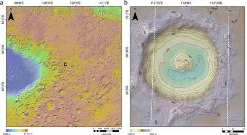
Figure 1. Location and elevation (MOLA; CitationZuber et al., 1992) map of Greg crater, Mars: (a) eastern Hellas impact basin in Mars’s southern hemisphere with Greg crater highlighted in the centre; (b) Greg crater as hillshade generated from the HRSC/MOLA blended elevation model, created using the Ames Stereo Pipeline (CitationBeyer et al., 2018) with 250 m contours. White vertical lines indicate the horizontal extent of the HRSC DEM used to create the blended DEM.
With respect to its large-scale morphology, Greg crater is archetypal of degraded complex craters in the region (CitationMest & Crown, 2014; CitationPotter, 1976), having a raised central peak ∼800 m higher than the crater floor and a poorly defined and complex outer rim. The geomorphology within Greg crater is, however, atypical of nearby craters. This was first noted by CitationHartmann and Thorsteinsson (2002), who described high concentrations of lobate deposits on the northernmost arc of the crater’s inner wall. Visible in images from the Mars Observer Camera on the Mars Global Surveyor satellite the appearance of these features, typically ∼5 km long, strongly suggested the downslope transport of viscous material (CitationMilliken et al., 2003). Similar features are located throughout the mid-latitudes of Mars (CitationSouness et al., 2012), which collectively have since been termed ‘glacier-like forms’ (GLFs; CitationHubbard et al., 2011). GLFs are end members of a continuum of ice-rich landforms that show evidence of flow called viscous flow features (VFFs; CitationMilliken et al., 2003; CitationSouness et al., 2012). Although exposed water ice cannot persist on interannual timescales outside of Mars’s polar regions today (CitationMilliken et al., 2003), VFFs are interpreted to have formed during periods of high obliquity in the planet’s recent geological past. Under this model, VFFs persist today owing to their protective layers of surface regolith, which retards sublimation (CitationHubbard et al., 2011).
Global climatic models driven by major changes in Mars’s obliquity predict high levels of atmospheric precipitation in the region of Eastern Hellas that includes Greg crater (CitationForget et al., 2006). The characteristically glaciated landscape within Greg crater, consisting of putative glaciers (GLFs) and dendritic valleys (CitationHartmann et al., 2014), appears to have been active within the last 100 Myr (Middle to Late Amazonian; CitationBerman et al., 2009; CitationHubbard et al., 2011). Accordingly, Greg crater has been well-studied with a strong focus on a cryospheric model of landscape evolution, the initial accumulation of which would necessitate major changes in orbital parameters during the last 100 Myr. However, alternative models of landscape evolution, which do not invoke recent climatic changes, have been proposed. These include the geothermal melting of ice under an exceptionally thick (>200 m) dust layer (CitationKargel et al., 2011), or deposition in a frozen lake/glaciolacustrine model (CitationKargel & Furfaro, 2012).
Geological and geomorphological maps provide a basis for interpreting landscape evolution, particularly for areas characterised by complex assemblages of landforms and terrain types, as in Greg crater. Elsewhere craters have been mapped at such detail, revealing a complex geological history of glacial and lacustrine interactions, aiding understanding of past martian climate (CitationPonderelli et al., 2005; CitationWilson et al., 2007). However, despite sustained interest in Greg crater, such a map has yet to be created. Regional maps (e.g. CitationMest & Crown, 2014) and small-scale maps (e.g. Figure 2a of CitationHartmann et al., 2014) do exist, but these lack detail, or focus on glaciofluvial landforms, and are therefore of limited use to those seeking to interpret the broad assemblage of landforms located within Greg crater. This restricts the formulation of hypotheses for Greg crater’s observed morphology, including the range of features not directly linked to glacial action, including valleys, (putative) fans, impact features and dunes. The aim of this paper is to present a comprehensive surficial geological and geomorphological map of these landforms, land features and terrain types to contribute to identifying and interpreting the processes that have shaped Greg crater.
2. Data, methods and software
Here, we used Context Camera (CTX; CitationMalin et al., 2007) images to distinguish and record landform assemblages within Greg crater and its immediate surroundings. In particular we used the beta01 Murray Lab CTX mosaic (CitationDickson et al., 2018)—a near seamless, non-destructive, and near-global mosaic of CTX images at 5 m/pixel (http://murray-lab.caltech.edu/CTX/index.html Last accessed 10-9-19). This beta01 CTX mosaic is a preliminary dataset, and care was exercised to ensure image artefacts (including seams and colour balancing) were not mapped as geologic contacts. We also made use of 100 m/pixel night-time infrared images from the Thermal Emission Imaging System (THEMIS; CitationChristensen et al., 2004; CitationEdwards et al., 2011) which helped discriminate morphological units on Greg’s surface. In its visual product, fine-grained or unconsolidated material appears dark (indicating low thermal inertia), cemented surfaces and those comprising sand grains appear as mid-tones (intermediate thermal inertia), and rocky surfaces or bed outcrops appear brighter due to their high thermal inertia (CitationPutzig & Mellon, 2007). The visual THEMIS product was used to help identification of Greg crater’s bedrock and ice-rich mantling deposits. High Resolution Imaging Science experiment (HiRISE; CitationMcEwen et al., 2007) images at 50 cm/pixel were used to aid our descriptions and interpretation of certain units (e.g. to help distinguish between bedrock outcrops on the crater floor and the surrounding material). Finally, we created a 100 m/pixel blended digital elevation model (DEM) using the Ames Stereo Pipeline (CitationBeyer et al., 2018), principally to digitise the crest of Greg crater and to map valleys, taking into consideration their 3D geometry. This blended DEM comprises the global ∼450 m/pixel Mars Orbiter Laser Altimeter DEM (MOLA; CitationZuber et al., 1992) and the 100 m/pixel High Resolution Stereo Camera DEM (HRSC; CitationJaumann et al., 2007), which only partially covers Greg crater. Although the blended pixel resolution is 100 m/pixel, we note that the effective DEM resolution is only 100 m/pixel in areas with HRSC DEM coverage (b).
Mapping was conducted in ArcGIS 10.5 at a fixed scale of 1:50,000, except for certain linear features, such as arcuate ridges, linear dunes and narrow valleys, that were mapped at a 1:25,000 scale to demarcate the orientation of their central axis clearly (whether a crest or a trough). All craters > 500 m in diameter were mapped using the CraterTools software, an add-in for ArcGIS, that allows craters to be digitised as best-fit ellipsoids independent of distortion due to map-projection (CitationKneissl et al., 2011). For all data, we used the GCS Mars 2000 coordinate system and Mercator projection (central meridian positioned at 113°E). The final map is presented at 1:100,000 scale (size A0; 100%).
3. Principal surficial units and features
Twenty-one geological/geomorphological units and features, categorised into seven thematic groups, were classified based on their location, shape, texture, and relief (). Interpretations were based on these properties, allied to the current understanding of process-form relationships, and guided by published interpretations from our study area and elsewhere on Mars, as noted in the following sections.
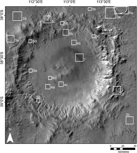
Figure 2. CTX mosaic (CitationDickson et al., 2018) of Greg crater showing locations of panels presented in .
3.1. Highlands and plains
3.1.1. Pre-existing bedrock
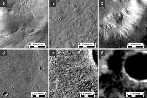
The pre-existing bedrock unit (a) comprises raised mountainous terrains distinct from Greg crater’s rim material. On a smaller scale, these terrains are part of nearby degraded crater rims and mountainous material. The bedrock appears rounded in the CTX imagery and is dissected by valleys typically 500 m wide and 10 km long. A thin layer of mantle deposit covers the pre-existing bedrock. The highly degraded appearance of this terrain, as well as its intersection by Greg’s rim, indicate that this unit predates the formation of Greg crater – consistent with the chronostratigraphy established by CitationMest and Crown (2014).
Figure 3. Terrain units located on and outside the rim of Greg crater: (a) pre-existing bedrock, (b) plains material, (c) Greg crater bedrock, (d) Greg crater ejecta, and (e and f) superposed crater ejecta. All panels are CTX images except (f), which is a night-time infrared THEMIS image. This figure, and all subsequent figures, are orientated northwards and have had their contrast stretched to help distinguish features.
3.1.2. Plains material
The plains material unit (b) consists of Eridania Planitia terrain. Distinguished by its knobby-textured and cratered flat surface, it shows no directional features linked to those found on Greg crater’s ejecta material (at 1:50,000 scale). CitationMest and Crown (2014) also noted yardang-like features in the plains material. As with locations elsewhere in our study site, it is likely covered by a thin layer of mantling deposit.
3.2. Impact features
3.2.1. Greg crater bedrock
Bedrock is exposed as raised terrain around Greg crater’s rim (c) and central peak. This exposed bedrock is rounded and appears substantially less cratered than adjacent ejecta material (Section 3.2.2). A thin layer of mantle deposit covers raised areas, and a thicker layer covers the valleys on the crater walls (Section 3.4). Some darker and more heavily textured areas on the crater floor appear to protrude above the material fill in HiRISE imagery. These appear white in THEMIS infrared night view images, suggesting higher thermal inertia than the surrounding material. Following CitationHartmann et al. (2014), we interpret these as ancient bedrock outcrops, their form being eroded by dendritic valleys (Section 3.7.1).
3.2.2. Greg crater ejecta
Greg crater is surrounded by a band of ejecta (d) generally comprising a smooth surface covered in a thin layer of mantle deposit. The ejecta material is considerably more cratered than the bedrock exposed in and around the crater’s rim (a), and is also commonly eroded by sinuous valleys, sometimes terraced (see Section 3.7). Except for a few impact craters < 1.5 km in diameter, which appear sharper and are likely younger, the features of this terrain are heavily degraded. Only limited ejecta blanket structure remains visible, including lineations and lobate deposits to the east and south east of our mapped area.
3.2.3. Superposed crater ejecta
The superposed crater ejecta unit (e) includes rim and ejecta blanket terrain from several younger craters > 3 km in diameter. The ejecta forms a well-preserved and well-defined continuous blanket of lobate outline, sometimes presenting radial lineation concentric to the impact that superpose Greg crater’s ejecta. The ejecta material has a wrinkled texture that occurs in proximity to mantling deposits. The ejecta of two large impacts east (39.36°S, 113.74°E) and northeast (37.95°S, 113.76°E) of Greg crater appear pitted, with dark spots visible in THEMIS night-time infrared images (f). These materials exhibit no evidence of fluvial activity and superpose valleys on Greg's rim and ejecta. Therefore, they appear to postdate local hydrological activity, consistent with the chronostratigraphy established by CitationMest and Crown (2014).
3.3. Greg crater floor
Greg crater’s floor is filled with fluvial, aeolian and mass wasted materials (CitationHartmann et al., 2014; CitationMest & Crown, 2014). Several terrains of different texture and structure are recognisable, although a clear delimitation cannot always be drawn. Three units were identified within this group.
3.3.1. Lobate superposed floor terrain
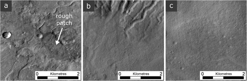
Lobate superposed floor terrain (a) describes the most textured area of Greg crater’s floor. Slightly raised lobate superposed structures are characteristic of this unit. The surface is maculated with relatively dark, rougher boulder-rich areas of bedrock protruding from the floor (CitationHartmann et al., 2014). It is otherwise cratered by small impacts and appears eroded by valleys. There is also a relatively high prevalence of sinuous ridges, up to ∼2 km long, raised above the surrounding terrain in this unit. Lobate superposed floor terrain is commonly draped by a layer of mantle deposit that is insufficiently thick to obscure underlying features. The lobate structures identified could be linked to alluvial fan systems (CitationHartmann et al., 2014) or to debris flows from the crater walls. This unit tends to grade into other Greg crater floor units, particularly along its northern edge. Where this boundary is difficult to delineate with confidence we indicate this uncertainty using a dashed line in the main map.
Figure 4. Terrain units located on the floor of Greg crater: (a) lobate superposed terrain, the arrow shows a patch of protruding rough bedrock, (b) common crater floor terrain, and (c) smooth crater floor terrain.
3.3.2. Common crater floor terrain
The common crater floor terrain unit (b) comprises intermediately textured terrains of Greg crater’s floor. Rougher patches of bedrock are also visible here, although less elongated and numerous than on the lobate superimposed floor terrain. The relatively smooth surface is cratered by impacts < 600 m in diameter and appears eroded by valleys that are sometimes terraced and usually larger (∼5-8 km in length) and more continuous than those located on the lobate superposed floor terrain. Valleys are traceable into the common crater floor unit for ∼3 km from the northern crater wall. Common crater floor terrain is also covered in what appears to be a thin layer of mantle deposit. Northeast of the central peak, this unit also hosts a deposit of dark, fine-grained material that fills valleys and craters, and forms dunes over an area of ∼250 km2 (Section 3.6).
3.3.3. Smooth crater floor terrain
Smooth crater floor terrain (c) comprises smooth terrain of low elevation located south of Greg crater’s central peak, covered by a mantling deposit of unknown thickness. Valleys and relatively small (less than ∼800 m diameter) impact craters within this unit appear degraded. The smooth crater fill is located downstream of numerous valleys running through the crater floor.
3.4. Ice-rich mantling deposits
Ice-rich mantling deposits fill the valleys all around Greg crater’s rim and craters throughout the mapped area. They are also present at the foot of pole-facing slopes. These mantling deposits show a range of textures that were subdivided into four categories: lineated, pitted, smooth and dune-dominated. These textures transition into one another (their boundary mapped as the approximate centreline of this transition) and appear to be at least partially dictated by slope, as described in relevant sections below.
In THEMIS night-time infrared imagery, areas covered in thicker mantling deposits appear dark, indicating low thermal inertia (CitationMellon et al., 2008). A similar observation was made by CitationHartmann et al. (2014) in Greg crater; comparable deposits of terrain draping units, referred to as latitudinal dependent mantle (LDM), are pervasive in the mid–high latitudes. Given its abundance elsewhere at similar latitudes (CitationKreslavsky & Head, 2002), we expect that units mapped here are ice-rich mantling deposits.
3.4.1. Lineated mantling deposits
Lineated mantling deposits (a) are characterised by pits, buttes and raised lineations. The deposits occupy steep (≥ ∼10°) pre-existing valleys and the edges of raised terrain. In narrow valleys (< 2 km wide), it forms a chevron texture (visible in CTX imagery), interpreted by CitationHartmann et al. (2014) to be due to a combination of sublimation lag forming knobby texture, and downslope transport with faster flow along the central valley axis. This texture is predominantly located on the southern wall of the crater which, at 12°, is steeper than the 9° northern wall (CitationBerman et al., 2009).
Figure 5. Terrain units (arrowed) formed of degraded icy material, predominantly found within the rim of Greg crater: (a) lineated mantling deposit, (b) pitted mantling deposit, (c) smooth mantling deposit, and (d) dune-dominated mantling deposit.
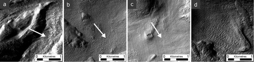
3.4.2. Pitted mantling deposits
Pitted mantling deposits (b) display a texture of pits and buttes at 1:50,000 scale that usually fills pre-existing alcoves, valleys and rims of raised areas with slopes lower than ∼10°. These are mainly found on the pole-facing inner wall and the outer walls of the crater (CitationBerman et al., 2009). Pits and buttes are related to sublimation processes (CitationBaker & Carter, 2019) and give no indication of flow.
3.4.3. Smooth mantling deposits
Smooth mantling deposits (c) appear smooth at 1:50,000 scale. They are commonly found on the northern inner wall covering glacier-like forms (GLFs) and transitioning to the crater floor.
3.4.4. Dune-dominated mantling deposits
Dune-dominated mantling deposits (d) are found on the inner rim of Greg crater and beyond the crater’s southern rim. The dunes appear to be transverse, indicating a roughly downslope wind direction on the inner rim of the crater (likely due to katabatic winds) and are aligned north–south outside the crater, implying a regional wind direction that is predominantly east–west. The spacing between crests is typically no more than ∼100 m. In the main map, a hatched symbol is used to indicate approximate crest direction.
3.5. Viscous flow features
Viscous flow features (VFFs; CitationMilliken et al., 2003) include several landforms that show evidence of gravity-driven downhill viscous flow, commonly bounded by lobate ridges (CitationSouness et al., 2012). Such flow is believed to occur by the deformation of water ice forming VFFs (CitationMilliken et al., 2003). Although the ice content of VFFs here is unknown, elsewhere up to 90% water ice content has been inferred (CitationHolt et al., 2008).
3.5.1. Concentric crater fill
Concentric crater fill (CCF) – a sub-type of VFF found throughout the mid to high latitudes (CitationLevy et al., 2010) – is a crater-filling unit found in the crater to the north east of Greg crater, superposed on its ejecta. Sharing the surface texture of VFF elsewhere (as well as extensive superposed mantling deposits) the lineations of the CCF mapped indicate both radial and concentric flow (a) of viscous material. Shared morphologies between CCF and other forms or VFFs is consistent with a common mode of origin (CitationDickson et al., 2012).
Figure 6. Viscous flow features (VFFs): (a) concentric crater fill (CCF), and (b) glacier-like forms (GLFs).
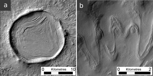
3.5.2. Glacier-like forms and arcuate ridges
Glacier-like forms (b) are the highest order (i.e. farthest upflow) VFFs, observed flowing into (CitationHubbard et al., 2011) and onto lower order VFFs (CitationHepburn et al., 2020), and are similar in appearance to valley glaciers on Earth (CitationSouness et al., 2012). In Greg crater, GLFs appear to be bound by bedrock above. They predominantly flow southwards down the inner slopes of Greg crater’s northern rim. The lowermost (i.e. downflow) boundary of GLFs is often defined by the presence of moraine-like arcuate ridges (sometimes nested), common on the southern facing slopes of Greg crater’s inner rim, and also on the outer slopes of its southern rim. Mantling deposits frequently overprint both arcuate ridges and GLFs, and we infer that GLFs underlie these deposits. Specific research attention has focused on Greg crater’s GLFs, reconstructing their extent (e.g. CitationArfstrom & Hartmann, 2005), surface composition, and flow history (CitationHubbard et al., 2011). As with VFFs elsewhere these GLFs are considered to be currently relict (e.g. CitationDickson et al., 2012; CitationHepburn et al., 2020). However, advanced (downflow) arcuate ridges suggest they may have reached their maximum activity during Mars’s last glacial maximum 4–6 Ma (CitationBrough et al., 2016).
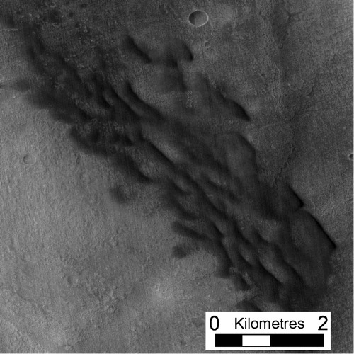
3.6. Dark dunes
A broad arcuate band of transverse dunes (CitationWard et al., 1985) wraps around the north and northeast side of Greg crater’s central peak (). These dunes differ from those present in the dune-dominated mantling deposits in size and texture, with spacing between crests ∼500 m. Although the dunes forming this band are somewhat irregular, they are typically hundreds of metres to several kilometres long and are aligned broadly parallel to the rim of the central peak. These dunes also appear to be asymmetric in cross-section (with the steeper face orientated towards the central peak) and formed of fine-grained material that is darker than their surroundings. Such transverse dunes generally form orthogonal to the direction of the wind responsible for their formation, with a relatively shallow stoss and steep lee face. Therefore, the orientation of dark dunes within Greg crater indicates that local winds may correspondingly blow radially towards its central pinnacle, particularly in the north and north east sectors of the crater’s floor.
Figure 7. Dark dunes located around the north and northeast side of the central peak.
3.7. Valleys and sinuous ridges
3.7.1. Valleys
Relict incisions appear as valleys (a and b) on many of the ground terrain types identified within Greg crater (e.g. b). Exceptions are more recent deposits formed of the ejecta from other craters (Section 3.2.3) and degraded icy material (Section 3.4). Valleys are typically several km long, forming dendritic and parallel networks. In certain cases, notably on the floor of Greg crater and ejecta mantle, valleys display terracing (b), indicating systematic variations in the elevation of past valley-forming processes, akin to fluvial features on Earth.
Figure 8. Valleys and sinuous ridges: (a) valley, (b) terraced valley, (c) sinuous ridge (shown by arrows).
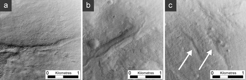
3.7.2. Sinuous ridges
Raised above the surrounding terrain are sinuous ridges (c). Some segments of these emerge from incised valleys, indicating a common origin subsequently altered by contrasting process domains, reflecting a possible change in the nature of a valley’s former sediment load or in the erodibility of the surrounding terrain (CitationBurr et al., 2010). In some instances, on Mars, sinuous ridges have been interpreted as eskers formed by sediment deposition beneath (warm-based) ice masses (CitationButcher et al., 2017; CitationGallagher & Balme, 2015). However, given the close relationship between sinuous ridges and valleys (and disconnect between GLFs), we suggest that both units form from fluvial processes.
4. Summary and conclusions
The geological landscape and geomorphological landforms of Greg crater, Mars, represent a focus of existing and continuing research, yet a large-scale map of the entire crater and its immediate surrounding has hitherto been unavailable. Here, we present such a map (main map), identifying 21 separate landforms or terrain types classified into seven landscape groups. In mapping these landforms and terrain types we identify numerous potential avenues for further research, including the following:
-
Analysing the distribution and orientation of dunes would provide insight into wind patterns within and around craters on Mars.
-
Mapping possible source areas for the material forming the dark dunes, as has been carried out elsewhere on Mars (e.g. CitationTirsch et al., 2011), would provide information on local or regional patterns of erosion, transport and deposition.
-
Comparing and contrasting the GLFs flowing southwards off the (outer) southern rim of Greg crater with those (already studied in detail) located inside the crater’s northern rim would contribute to understanding of the processes of GLF formation and/or preservation.
-
Modelling flow and geometry of former GLFs, possibly allied to DEM generation from overlapping CTX and/or HiRISE images (e.g. CitationHepburn et al., 2019), would improve knowledge of GLF dynamics and of the links between GLFs and martian climate change. Specific issues to be explored could include driving time-evolving GLF change with outputs from global circulation models for Mars, reconstructing multiple glacial advances by matching maximum modelled GLF extents to nested moraine sequences, and evaluating the likelihood of wet-based glaciation beneath thickest ice during periods of maximum GLF extent.
-
Investigating the apparent asymmetry in the slope of Greg crater’s inner walls (with the southern rim being steeper (∼12°) than the northern rim (∼9°)) would yield information relating to the original impact and/or to large-scale variations in surface properties.
-
Modelling the incision of Greg crater’s fluvial valleys would provide information relating to former water discharge and regional climate. Modelling multiple phases of channel incision, as evidenced by terraced channels, would provide additional information relating to variability in this climate history.
Software
ArcGIS 10.5 was used to produce the Main Map, with the CraterTools add-in used to digitise craters > 500 m diameter. The open source Ames Stereo Pipeline was used to create the DEM that aided feature identification.
Surficial Geology and Geomorphology of Crater Greg, eastern Hellas Planitia, Mars
Download PDF (87.9 MB)Acknowledgements
A.J. Hepburn is funded by an AberDoc PhD scholarship. We thank the reviewers and editors for their thorough and constructive comments that helped improve the quality of this manuscript and the main map.
Disclosure statement
No potential conflict of interest was reported by the author(s).
References
- Arfstrom, J. , & Hartmann, W. K. (2005). Martian flow features, moraine-like ridges, and gullies: Terrestrial analogs and interrelationships. Icarus , 174 (2), 321–335. https://doi.org/10.1016/j.icarus.2004.05.026
- Baker, D. M. , & Carter, L. (2019). Probing supraglacial debris on Mars 1: Sources, thickness, and stratigraphy. Icarus , 319 , 745–769. https://doi.org/10.1016/j.icarus.2018.09.001
- Berman, D. C. , Crown, D. A. , & Bleamaster, L. F. (2009). Degradation of mid-latitude craters on Mars. Icarus , 200 (1), 77–95. https://doi.org/10.1016/j.icarus.2008.10.026
- Beyer, R. A. , Alexandrov, O. , & McMichael, S. (2018). The Ames Stereo Pipeline: NASA’s open source software for deriving and processing Terrain data. Earth and Space Science , 5 (9), 537–548. https://doi.org/10.1029/2018EA000409
- Brough, S. , Hubbard, B. , & Hubbard, A. (2016). Former extent of glacier-like forms on Mars. Icarus , 274 , 37–49. https://doi.org/10.1016/j.icarus.2016.03.006
- Burr, D. M. , Williams, R. M. E. , Wendell, K. D. , Chojnacki, M. , & Emery, J. P. (2010). Inverted fluvial features in the Aeolis/Zephyria Plana region, Mars: Formation mechanism and initial paleodischarge estimates. Journal of Geophysical Research: Planets , 115 (E7), E07011. https://doi.org/10.1029/2009JE003496
- Butcher, F. E. G. , Balme, M. R. , Gallagher, C. , Arnold, N. S. , Conway, S. J. , Hagermann, A. , & Lewis, S. R. (2017). Recent basal melting of a mid-latitude glacier on Mars. Journal of Geophysical Research: Planets , 122 (12), 2445–2468. https://doi.org/10.1002/2017JE005434
- Christensen, P. R. , Jakosky, B. M. , Kieffer, H. H. , Malin, M. C. , McSween Jr., H. Y. , Nealson, K. , Mehall, G. L. , Silverman, S. H. , Ferry, S. , Caplinger, M. , & Ravine, M. (2004). The Thermal Emission Imaging System (THEMIS) for the Mars 2001 Odyssey mission. Space Science Reviews , 110 (1/2), 85–130. https://doi.org/10.1023/B:SPAC.0000021008.16305.94
- Dickson, J. L. , Head, J. W. , & Fassett, C. I. (2012). Patterns of accumulation and flow of ice in the mid-latitudes of Mars during the Amazonian. Icarus , 219 (2), 723–732. https://doi.org/10.1016/j.icarus.2012.03.010
- Dickson, J. L. , Kerber, L. A. , Fassett, C. I. , & Ehlman, B. L. (2018). A global, blended CTX mosaic of Mars with vectorized seam mapping: a new mosaicking pipeline using principles of non-destructive image editing. 49th Lunar and Planetary Science Conference, Abstract #2480.
- Edwards, C. S. , Nowicki, K. J. , Christensen, P. R. , Hill, J. , Gorelick, N. , & Murray, K. (2011). Mosaicking of global planetary image datasets: 1. Techniques and data processing for Thermal Emission Imaging System (THEMIS) multi-spectral data. Journal of Geophysical Research: Planets , 116 (E10), E10008. https://doi.org/10.1029/2010JE003755
- Forget, F. , Haberle, R. M. , Monmessin, F. , Levrard, B. , & Head, J. W. (2006). Formation of Glaciers on Mars by Atmospheric Precipitation at High Obliquity. Science , 311 (5759), 368–371. https://doi.org/10.1126/science.1120335
- Gallagher, C. , & Balme, M. (2015). Eskers in a complete, wet-based glacial system in the Phlegra Montes region, Mars. Earth and Planetary Science Letters , 431 , 96–109. https://doi.org/10.1016/j.epsl.2015.09.023
- Hartmann, W. K. , Ansan, V. , Berman, D. C. , Mangold, N. , & Forget, F. (2014). Comprehensive analysis of glaciated martian crater Greg. Icarus , 228 , 96–120. https://doi.org/10.1016/j.icarus.2013.09.016
- Hartmann, W. K. , & Thorsteinsson, T. (2002). Comparison of Icelandic and Martian Hillside Gullies. 33rd Lunar and Planetary Science Conference, Abstract #1904.
- Hepburn, A. J. , Holt, T. , Hubbard, B. , & Ng, F. (2019). Creating HiRISE digital elevation models for Mars using the open-source Ames Stereo Pipeline. Geoscientific Instrumentation, Methods and Data Systems , 8 (2), 293–313. https://doi.org/10.5194/gi-8-293-2019
- Hepburn, A. J. , Ng, F. , Livingstone, S. J. , Holt, T. , & Hubbard, B. (2020). Polyphase mid-latitude glaciation on Mars:Chronology of the formation of superposed glacier-like forms from crater-count dating. Journal OfGeophysical Research: Planets , 125 , e2019JE006102. https://doi.org/10.1029/2019JE006102
- Holt, J. W. , Safaeinili, A. , Plaut, J. J. , Head, J. W. , Phillips, R. J. , Seu, R. , Kempf, S. D. , Choudhary, P. , Young, D. A. , Putzig, N. E. , Biccari, D. , & Gim, Y. (2008). Radar sounding evidence for buried glaciers in the Southern Mid-Latitudes of Mars. Science , 322 (5905), 1235–1238. https://doi.org/10.1126/science.1164246
- Hubbard, B. , Milliken, R. E. , Kargel, J. S. , Limaye, A. , & Souness, C. (2011). Geomorphological characterisation and interpretation of a mid-latitude glacier-like form: Hellas Planitia, Mars. Icarus , 211 (1), 330–346. https://doi.org/10.1016/j.icarus.2010.10.021
- Jaumann, R. , Neukum, G. , Behnke, T. , Duxbury, T. C. , Eichentopf, K. , Flohrer, J. , Gasselt, S. v. , Giese, B. , Gwinner, K. , Hauber, E. , Hoffmann, H. , Hoffmeister, A. , Köhler, U. , Matz, K.-D. , McCord, T. B. , Mertens, V. , Oberst, J. , Pischel, R. , Reiss, D. , … the HRSC Co-Investigator Team (2007). The high-resolution stereo camera (HRSC) experiment on Mars Express: Instrument aspects and experiment conduct from interplanetary cruise through the nominal mission. Planetary and Space Science , 55 (7–8), 928–952. https://doi.org/10.1016/j.pss.2006.12.003
- Kargel, J. S. , & Furfaro, R. (2012). A frozen lake/glaciolacustrine model of crater Greg (Mars). 43rd Lunar and Planetary Science Conference, Abstract #2629.
- Kargel, J. S. , Furfaro, R. , Wibben, D. , Berman, D. , Hubbard, B. , Milliken, R. , Pelletier, J. , & Rodriguez, J. A. (2011, March 7–11). Melting a martian viscous flow feature: A modern-climate, dust-blanketed glacier model . 42nd Lunar and Planetary Science Conference, Abstract #2266.
- Kneissl, T. , Van Gasselt, S. , & Neukum, G. (2011). Map-projection-independent crater size-frequency determination in GIS environments - New software tool for ArcGIS. Planetary and Space Science , 59 (11–12), 1243–1254. https://doi.org/10.1016/j.pss.2010.03.015
- Kreslavsky, M. A. , & Head III J. W. (2002). Mars: Nature and evolution of young latitude-dependent water-ice-rich mantle. Geophysical Research Letters , 29 (15), 14–11. https://doi.org/10.1029/2002GL015392
- Levy, J. , Head, J. W. , & Marchant, D. R. (2010). Concentric crater fill in the northern mid-latitudes of Mars: Formation processes and relationships to similar landforms of glacial origin. Icarus , 209 (2), 390–404. https://doi.org/10.1016/j.icarus.2010.03.036
- Malin, M. C. , Bell, J. F. , Cantor, B. A. , Caplinger, M. A. , Calvin, W. M. , Clancy, R. T. , Edgett, K. S. , Edwards, L. , Haberle, R. M. , James, P. B. , Lee, S. W. , Ravine, M. A. , Thomas, P. C. , & Wolff, M. J. (2007). Context Camera Investigation on board the Mars Reconnaissance Orbiter. Journal of Geophysical Research: Planets , 112 , E05S04. https://doi.org/10.1029/2006JE002808
- McEwen, A. S. , Eliason, E. M. , Bergstrom, J. W. , Bridges, N. T. , Hansen, C. J. , Delamere, W. A. , Grant, J. A. , Gulick, V. C. , Herkenhoff, K. E. , Keszthelyi, L. , & Kirk, R. L. (2007). Mars reconnaissance orbiter's high resolution imaging science experiment (HiRISE). Journal of Geophysical Research: Planets , 112 (E5). https://doi.org/10.1029/2005JE002605
- Mellon, M. T. , Fergason, R. L. , & Putzig, N. E. (2008). The thermal inertia of the surface of Mars. In J. Bell (Ed.), The martian surface: Composition, mineralogy and physical properties (pp. 399–427). Chapter 18, Cambridge University Press. http://doi.org/10.1017/CBO9780511536076.019
- Mest, S. C. , & Crown, D. A. (2014). Geologic map of MTM –30247, –35247, and –40247 quadrangles, Reull Vallis region of Mars. U.S. Geological Survey Scientific Investigations, Map 3245, pamphlet 20 p., scale 1:1,000,000. http://dx.doi.org/10.3133/sim3245
- Milliken, R. E. , Mustard, J. F. , & Goldsby, D. L. (2003). Viscous flow features on the surface of Mars: Observations from high-resolution Mars Orbiter Camera (MOC) images. Journal of Geophysical Research: Planets , 108 , E65057. https://doi.org/10.1029/2002JE002005
- Ponderelli, M. , Baliva, S. , Di Lorenzo, S. , Marinangeli, L. , & Rossi, A. P. (2005). Complex evolution of paleolacustrine systems on Mars: An example from the Holden crater. Journal of Geophysical Research: Planets , 110 (E4), E04016. https://doi.org/10.1029/2004JE002335
- Potter, D. B. (1976). Geologic map of the Hellas Quadrangle of Mars. U.S. Geological Survey Miscellaneous Investigations Series, Map 941. https://doi.org/10.3133/i941
- Putzig, N. E. , & Mellon, M. T. (2007). Apparent thermal inertia and the surface heterogeneity of Mars. Icarus , 191 (1), 68–94. https://doi.org/10.1016/j.icarus.2007.05.013
- Souness, C. , Hubbard, B. , Milliken, R. E. , & Quincey, D. (2012). An inventory and population-scale analysis of martian glacier-like forms. Icarus , 217 (1), 243–255. https://doi.org/10.1016/j.icarus.2011.10.020
- Tirsch, D. , Jaumann, R. , Pacifici, A. , & Poulet, F. (2011). Dark aeolian sediments in Martian craters: Composition and sources. Journal of Geophysical Research , 116 (E3), E03002. https://doi.org/10.1029/2009JE003562
- Ward, A. W. , Doyle, K. B. , Helm, P. J. , Weisman, M. K. , & Witbeck, N. E. (1985). Global map of aeolian features on Mars. Journal of Geophysical Research: Solid Earth , 90 (B2), 2038–2056. https://doi.org/10.1029/JB090iB02p02038
- Wilson, S. A. , Howard, A. D. , Moore, J. M. , & Grant, J. A. (2007). Geomorphic and stratigraphic analysis of Crater Terby and layered deposits north of Hellas basin. Mars. Journal of Geophysical Research: Planets , 112 , E08009. https://doi.org/10.1029/2006JE002830
- Zuber, M. T. , Smith, D. E. , Solomon, S. C. , Muhleman, D. O. , Head, J. W. , Garvin, J. B. , Abshire, J. B. , & Bufton, J. L. (1992). The Mars observer laser altimeter investigation. Journal of Geophysical Research: Planets , 97 (E5), 7781–7797. https://doi.org/10.1029/92JE00341