
 ?Mathematical formulae have been encoded as MathML and are displayed in this HTML version using MathJax in order to improve their display. Uncheck the box to turn MathJax off. This feature requires Javascript. Click on a formula to zoom.
ABSTRACT
A near-equiatomic FeCoNiCuAl High-entropy alloy (HEA) was produced using laser powder bed fusion (L-PBF) pre-alloy powder. Microstructural characteristics and tribological properties of L-PBF specimens under various volumetric energy densities (VEDs) were investigated in detail. The results showed that the phase of L-PBF specimen consisted of BCC matrix + Cu-rich B2 precipitate. The microstructure of L-PBF specimen largely consisted of columnar grains perpendicular to the melt pool boundary (MPB) direction owing to the epitaxial growth along the temperature gradient. The preferred orientation of the L-PBF specimen was gradually transformed from the order of <001> to <101> as the VED rose. Larger size precipitates re-appeared and wider MPB were formed upon faster remelting and steeper cooling as a result of higher VED. Compared to the components produced by spark plasma sintering (SPS), L-PBF specimens presented better wear resistance owing to the ultra-fine substructure and nano-scaled precipitates. In addition, the L-PBF specimen produced with 83 J/mm3 VED exhibits the highest elastic strain to failure (H/Er) and yield stress (H2/Er3).
1. Introduction
With the ever-increasing demand for superior hardness, wear ability, and corrosion resistance of complexly shaped parts used in industries, traditional metallic alloys formed by one or two dominant elements and a number of minorities are hard to meet these requirements (Gludovatz et al. Citation2014; Li et al. Citation2019; Zhu et al. Citation2020). Since the concept of high-entropy alloy (HEA) was proposed by Yeh et al. (Citation2004), a series of HEAs, such as CoCrFeMoNi, VnbMoTaW and AlLiMgScTi, with excellent mechanical properties have been developed in the past decade (Li et al. Citation2018; Xin et al. Citation2018; Youssef et al. Citation2015). In general, an HEA is composed of at least five or more principal elements with an (near) equal mixing ratio. The high mixing entropy and small atomic size differences can slow diffusion and increase lattice distortion, thereby leading to the formation of a single or double phase crystalline structure such as face-centered cubic (FCC), body-centered cubic (BCC), or FCC + BCC (George, Curtin, and Tasan Citation2020). Recent studies have shown that adjusting the alloying elements is able to obtain the desired phases in HEA (Borkar et al. Citation2016; Zhang et al. Citation2017; Fang et al. Citation2018). For instance, as the Al content increases (x = 0.3, 0.6 and 0.85), the phase of AlxCoCrFeNi HEA changes from a disordered FCC to FCC + disordered BCC, and to BCC + ordered B2 (Joseph et al. Citation2017). In addition, it has been proven that the addition of Cu element can remarkably increase the structural energy difference (ΔE), resulting in a single FCC homogenous FeCoNi(Cu1.0Al)x at arbitrary temperatures (ideal state) (Yu et al. Citation2020). This means that Cu, as an FCC stabiliser, could make FeCoNiCuAl HEAs have a dual-phase structure of FCC + BCC. To avoid the segregation of alloying elements, a high cooling rate is desired. However, the natural intricacy of the HEA makes it difficult to ensure homogeneity of microstructures and suppress the formation of undesired precipitated compounds by using conventional methods, e.g. arc melting or casting (Joseph et al. Citation2015; Nagase et al. Citation2019). Additionally, due to its high hardness, it becomes rather challenging to process HEAs into complex-shaped structures in subsequent production.
Additive manufacturing (AM) presents a group of emerging technologies that a 3D complex shaped structure can be built by adding a tiny amount of material at one time, layer upon layer, guided by a computer model. AM technologies can offer great potential to rapidly manufacture high quality components at minimum waste regardless the geometric complexity (Herzog et al. Citation2016). Laser powder bed fusion (L-PBF) is one of the most significant and popular technologies in metal AM technologies (Long et al. Citation2018; Yin et al. Citation2019), which is able to manufacture functional parts with outstanding mechanical properties by using metal powders as the feedstock (Yu et al. Citation2019; Han et al. Citation2020b). This anomalous strengthening ascribes to the formation of ultrafine cellular subgrains, metastable phases and supersaturated solid solution caused by the extremely high cooling rate (103–108 K/s) during L-PBF processing (Wang et al. Citation2018; Messé et al. Citation2018; Zhao et al. Citation2019). To date, few studies on the L-PBF of FeCoNiCuAl HEAs are reported, but the formability and the microstructural evolution under various volumetric energy density (VED) are not clear yet (Han et al. Citation2020a). Whether the L-PBF FeCoNiCuAl HEA can still retain the FCC and BCC dual-phase or not remains in question. Although the laser-cladded FeCoNiCuAl HEA coating is composed of FCC and BCC phases with a typical dendritic microstructure (Jin et al. Citation2018), it is still unsure whether a second phase precipitate will appear during L-PBF processing or not, as the thermal history in L-PBF is rather different from that in laser cladding (Ma, Wang, and Zeng Citation2017). Therefore, to achieve a better understanding of the formability, microstructural evolution, and mechanical properties of the FeCoNiCuAl high-entropy alloy in the regards of L-PBF, it is worth investigating how the material behaves under different VEDs.
In the present study, the effect of various VEDs on densification, phase composition, and microstructural evolution in L-PBF FeNiCoAlCu HEA will be investigated. The relationship between microstructure and properties, including nano-indentation hardness and tribological behaviours, are discussed in detail. A comparison study on the wear resistance was carried out by utilising a specimen produced by spark plasma sintering (SPS) to understand the influence of the microstructure on tribological properties.
2. Experimental details
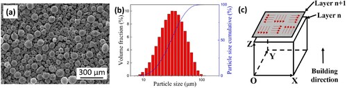
The equimolar FeCoNiCuAl HEA spherical pre-alloyed powders were prepared by an HERIMGA-100-20 close-coupled gas atomisation system (Phoenix Scientific Industries Ltd, UK) in a high-purity argon environment (>99.9%), see (a). The particle size distribution of the powders is shown in (b), i.e. the size ranges from 15 to 65 μm with an average size around 33 μm. Cubic specimens with a dimension of 10 mm × 10 mm × 10 mm were produced using an FS121M L-PBF machine equipped with 500 W fibre laser with 60 μm spot size (Farsoon Inc., China). The L-PBF chamber was flushed with high-purity Ar gas with an oxygen content less than 100 ppm throughout the process. The process parameters used to build the specimens were as following, the laser power (P) ranged between 100 and 400 W, the scanning velocity (v) was 400–1200 mm/s, the layer thickness (t) was 40 μm and the hatch space (h) was 80 μm. Herein, an integrated parameter VED, was introduced and defined as:
(1)
(1) Thus, specimens with various VED from 25 to 109 J/mm3 are presented in this work. The building platform was preheated to 120°C. The scanning strategy was a ‘checkboard’ type where the scanning direction rotated 67° between each layer. Different planes of the L-PBF FeCoNiCuAl specimen are shown in (c), where XY-plane represents the building plane and XZ-plane represents the building direction plane. The pre-alloyed powders were sintered at 1000°C for 10 min holding time by SPS furnace (SPS; FCT D25/3, Germany) with a heating rate of 100°C/min.
Figure 1. (a) Powder morphology, (b) powder size distribution, and (c) schematic of the XY- and XZ-planes and the checkboard scanning strategy.
The chemical composition of the powder and L-PBF specimens were examined by inductively coupled plasma optical emission spectrometry (ICP-OES), as listed in . The density of specimens was measured by Archimedes method (a theoretical density ∼7.47 g/cm3 was used). Phase identification was analysed by X-ray Diffraction (XRD) using Cu-Kα radiation. The 2θ scanning ranged from 10° to 90° with a step size of 0.02°. The specimens were ground, polished, and etched by a solution containing 30% HNO3 and 70% alcohol (% in volume) before examining the microstructures and textures in an FEI Quanta FEG250 scanning electron microscope with an X-ray energy dispersive spectroscopy (EDS), and an electron backscatter diffraction (EBSD) detector. To further characterise the precipitates in finer detail, specimens were extracted from certain areas and observed in a transmission electron microscope (TEM, FEI Talos F200X 300 kV) equipped with high resolution transmission electron microscope (HRTEM) and selective area electron diffraction (SAED). Nanoindentation tests were carried out on a nano-indenter (GSM) by applying a maximum indentation load of 30 mN for 15 s. The reduced Young's modulus (Er) of the specimen is extracted from the contact stiffness (S, measured by the upper portion of the unloading data) divided by the contact area Ac as following (Oliver and Pharr Citation1992):
(2)
(2) where hc is the contact depth under the peak load. Dry sliding wear tests were performed on a ball-on-disk HT 1000 machine in ambient environment (temperature: 28–30°C, humidity: 60%). A 6 mm diameter SiC ball with a load of 10 N was applied. The sliding velocity was fixed at 125 mm/s and the wear time lasted for 30 min. The wear loss was measured by a FA2104 precision balance. The morphologies and compositions of the worn surfaces were examined by the scanning electron microscope.
Table 1. Exact chemical composition of powder, L-PBF, and SPS specimens.
3. Results
3.1. Densification of L-PBF FeCoNiCuAl
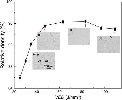
presents the density of L-PBF FeCoNiCuAl specimens built with different VEDs. The corresponding optical micrographs in XZ-plane are also depicted in the inset. The relative density of the specimens is firstly increased from ∼86% to ∼96%, but slightly dropped to ∼95%, where the VED increases from 25 to 109 J/mm3. Relatively larger amount of pores was found in the lower VED case owing to the lack of fusion, which was the main reason for the low density, as shown in (a). A high VED can not only reduce the viscosity of liquid metal but also enhance the flowability, thereby effectively inhibit the formation of pores defects (Xia et al. Citation2016). A close look at (c), a few microcracks could still discern. This suggests that the hot cracking might be the main dilemma for the formability of L-PBF FeCoNiCuAl. As the VED further increased, the density of specimens decreased slightly. This can be explained that an excessively higher VED could cause turbulent flow in the melt pool, which could trap the argon gas and form some extra pores (Dai et al. Citation2020), as shown in (d).
Figure 2. Relationship between VED and density of L-PBF FeCoNiCuAl specimens. The corresponding XZ-plane optical images are labelled on the graph.
3.2. Phase analysis
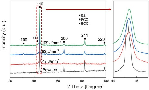
Typical XRD patterns of pre-alloyed FeCoNiCuAl powder and bulk L-PBF specimens with various VED (from 47 to 109 J/mm3) are presented in (a). Obviously, the virgin gas-atomised powder has two phases (FCC and B2/BCC) while the FCC peak (111) in L-PBF parts appears to weaken owing to the high cooling rate. This means a super-saturated BCC solid solution could be formed during L-PBF. It is evident in that all diffraction peaks of L-PBF specimens are shifted to the higher 2θ angle side compared with the virgin powder, suggesting that the evaporation of Al element () caused by the laser melting could lead to the decrease of lattice constant. The vacancies formed by the evaporation are possible to retain owing to sluggish diffusion. In addition, the half-height width of L-PBF specimen becomes broader than that of the original powder, which implies that the finer grain size could be formed by L-PBF (Geng, Kang, and Min Citation2004).
Figure 3. XRD spectra of FeCoNiCuAl powder and L-PBF parts for various VED.
3.3. Microstructural evolution
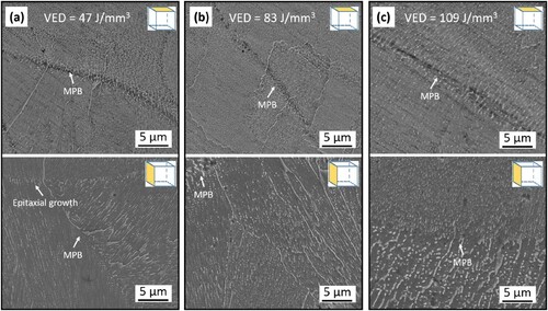
presents the XY- and XZ-plane secondary electron (SE) images of the L-PBF specimens with various VEDs ranges from 47 to 109 J/mm3. Both the cellular networks and columnar grains could be observed in the XY-plane (details in Figure S1). As the VED increases, this unique microstructure becomes bright nanoparticles distributed along the maximal thermal dissipation direction. The melt pool boundary (MPB) in both XY- and XZ-plane can be clearly identified. In XY-plane, the size of cellular networks inside the melt track is apparently coarser than that in the MPB ((a)), and these cellular networks in MPB have been replaced by granular microstructures at a higher VED (109 J/mm3). However, there are no cellular networks in the XZ-plane. Bunches of columnar grains grow perpendicular to the direction of the MPB, which illuminates the heat flow direction during L-PBF processing (Chen, Phan, and Darvish Citation2017). Besides, MPB does not prevent the epitaxial growth of columnar grains, as marked in (a). The precipitates inside the melt pool upon cooling and re-precipitates in MPB by the heat conduction from the following scans are much more severe at higher VED (Xiong et al. Citation2019). This is responsible for the formation of larger size re-precipitates and wider MPB as the VED increases.
Figure 4. SE images of L-PBF FeCoNiCuAl specimens for various VEDs: (a) 47 J/mm3, (b) 83 J/mm3 and (c) 109 J/mm3.
3.4. TEM analysis
The bright field (BF) TEM image shown in displays finer details of XZ-plane of the L-PBF specimen produced with a VED of 83 J/mm3. It shows a polycrystalline structure with plentiful regularly arranged precipitates in nanometer scale. The corresponding SAED (inset of (a)) pattern shows the disordered BCC phase (matrix) in the [−111] zone axis. The higher magnification in (b) clearly shows that the nano-scaled precipitates (about 90 nm) are dispersed parallel along the heat flow direction in the matrix. Dislocation tangles are present around the nano-scaled precipitates. The inset of (b) shows the SAED pattern indexed along the [001] zone axis of the BCC phase from the precipitate, clearly indicating the diffraction spots corresponding to the superlattice of the ordered BCC (B2) phase. The HRTEM image and corresponding enlarged Fourier-filtered HRTEM are shown in (c). It is evident that a high density of dislocations and stacking faults coexists in the precipitates. Combined with the EDS point analysis results, this nano-scaled precipitate is considered as Cu-rich B2 phase.
Figure 5. TEM analysis of L-PBF FeCoNiCuAl alloy (VED = 83 J/mm3): (a) BF image shows a polycrystalline BCC structure, confirmed by the inserted [−111] zone axis SAED; (b) high-magnification BF image of Cu-rich nano-scaled B2 precipitates, confirmed by the inserted [001] zone-axis SAED; (c) HRTEM image of a precipitate along with the FFTs; (d) corresponding EDS point analysis results.
![Figure 5. TEM analysis of L-PBF FeCoNiCuAl alloy (VED = 83 J/mm3): (a) BF image shows a polycrystalline BCC structure, confirmed by the inserted [−111] zone axis SAED; (b) high-magnification BF image of Cu-rich nano-scaled B2 precipitates, confirmed by the inserted [001] zone-axis SAED; (c) HRTEM image of a precipitate along with the FFTs; (d) corresponding EDS point analysis results.](/cms/asset/54b8414c-b5bd-4e4c-afbf-9709695d5020/nvpp_a_1848284_f0005_oc.jpg)
3.5. EBSD and texture analysis
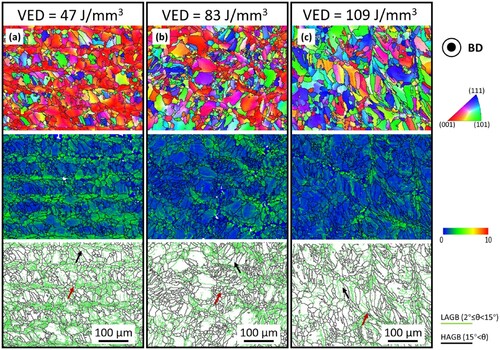
The EBSD analysis depicted in presents the microstructural evolution of L-PBF specimens for various VEDs. All EBSD maps were taken from the XY-plane perpendicular to the building direction. The inverse pole figure (IPF) clearly exhibits the typical melt track morphology with a rotation angle of 67°. The averaged distance between parallel equiaxed grain zones is about 80 μm, which is consistent with the hatching space. Equiaxed grains (marked by red arrows) mainly exist in the melt track boundary, while the majority of grains inside the melt track are still in columnar shape (marked by black arrows). Although the average grain size of all the L-PBF specimens is around 10 μm, the proportion of small-sized grains is increased at high VED (Figure S2). The Pole Figures (PF) and IPF shown in Figure S3 indicate that the L-PBF specimen has a strong preferred orientation in <001> at a lower VED (47 J/mm3), and is gradually transformed into a weaker <101> at a higher VED (109 J/mm3). It is well-known that the preferred orientation for cubic metals is <001>. Generally, the grain growth direction is parallel to the direction of maximum temperature gradient (perpendicular to the MPB). As the VED increases, the melt pool changes from shallow to deep, and the degree of melt flow fluctuation and multiple re-melting intensifies. Thus, the orientation of the grain is weakened and changed. Kernel average misorientation (KAM) map reveals the average misorientation between each pixel and its nearest neighbours. In this study, the KAM plot is used to estimate the degree of deformation in grains. Blue colour (0°) marks grains without any misorientation, whereas red colour (10°) denotes those of highest misorientation (Zhou et al. Citation2019). The specimen produced with 47 J/mm3 VED shows an intense local deformation, indicating the presence of high strain concentration. However, the specimen produced with 109 J/mm3 VED only retains partial residual strain and manifests less green traces in the blue matrix. Therefore, it can be seen that a larger VED leads to less degree of misorientation in the L-PBF specimens. Besides, it is evident that all L-PBF specimens are composed of large angle grain boundaries regardless the VED is at low or high level. A large amount of low angle grain boundaries (LAGBs) and high density of geometrically necessary dislocations (GNDs) can also be found. The HAGBs provide a larger driving force for grain boundary segregation, which can contribute to the segregation of Cu at the subgrain boundary (Figure S1) (Wang et al. Citation2020). It is worth noting that high angle grain boundaries (HAGBs) gradually decrease from 76% to 64% while the VED was increased from 47 to 109 J/mm3.
Figure 6. Inverse pole figure (IPF), Kernel average misorientation (KAM) maps, and Image quality (IQ) maps of L-PBF FeCoNiCuAl HEAs for various VEDs: (a) 47 J/mm3, (b) 83 J/mm3 and (c) 109 J/mm3.
3.6. Hardness and wear behaviour
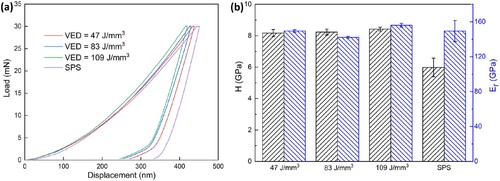
(a) shows the nanoindentation load-depth curves collected from L-PBF and SPS specimens. It can be observed that the indentation depth on L-PBF specimens decreases gradually with the increase of VED. On the contrary, the SPS specimen has the largest depth indicating the lowest hardness. The corresponding nano-hardness, depicted in (b), it increases slightly with the increase of VED from ∼8.17 GPa at 47 J/mm3 to ∼8.42 GPa at 109 J/mm3. This enhancement of hardness is probably attributed to the extremely high cooling rate (fine grain) and severe re-melting (large precipitate) at higher VED. Surprisingly, the lowest reduced Young’s modulus (∼142 GPa) is recorded on the specimen produced with a VED of 83 J/mm3. It is well known that the Young's modulus exhibits pronounced anisotropy in single crystal (Wang, Todai, and Nakano Citation2019). Recent studies (Kunze et al. Citation2015; Karre, Niranjan, and Dey Citation2015) have shown that Young's modulus is also highly correlated with crystallographic orientations, even in a BCC-structured crystal. For example, Ishimoto et al. (Citation2017) demonstrated that Young’s modulus of L-PBF Ti–15Mo–5Zr–3Al alloy along the <011> orientation (∼100 GPa) was much higher than that along the <001> orientation (∼68 GPa). This phenomenon is highly consistent with our results in this study. For the specimen produced with 47 J/mm3 VED, the abnormally high reduced Young's modulus is probably attributed to the high residual stress (Dong, Du, and Zhang Citation2013). The error bars for SPS specimens are obvious wider, and the hardness has decreased significantly (∼5.98 GPa).
Figure 7. (a) Load-displacement curves and the (b) values of H and Er.
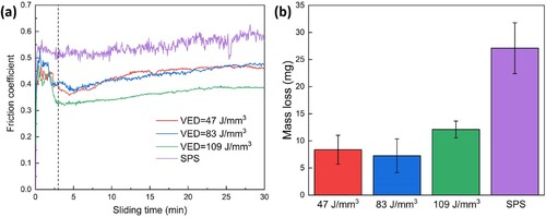
The friction coefficients versus sliding time and mass losses of both the L-PBF and SPS specimens are shown in . The friction coefficient curves of L-PBF specimens fluctuate within a short run-in period (about 3 min) and then become stable. The average friction coefficients of L-PBF specimens produced with 47, 83, and 109 J/mm3 VEDs in steady wear state are calculated as 0.442, 0.438, and 0.365, respectively. For SPS specimens, it shows a high friction coefficient (0.542) with a large fluctuation. Concerning the wear loss ((b)), the specimen produced with 83 J/mm3 VED exhibits the lowest wear loss of about 7.3 mg. One can notice that this specimen does not present the highest hardness. As the VED reached to 109 J/mm3, the wear loss increases up to 12.1 mg. In addition, the wear loss of SPS specimens (∼27.1 mg) is significantly higher than that of L-PBF specimens.
Figure 8. (a) Friction coefficients versus sliding time and (b) mass loss for the L-PBF and SPS specimens.
shows the details about worn surfaces and corresponding EDS mappings of the L-PBF and SPS specimens. The SPS specimen shows an irregular and rough worn surface with severe plastic deformation ((d)). Combined with the results of EDS mapping, the wear of SPS specimens is mainly attributed to the following two mechanisms, which are delamination and oxidative wear. At the beginning of sliding, the specimen surface is in tangential contact with the SiC ball. Large strain is induced by a small contact surface resulting in relative high friction coefficients in the early stage of run-in period. Once the local pressure exceeds the yield stress of the materials, microcracks are preferentially formed in the soft FCC matrix (Prashanth et al. Citation2014). Meanwhile, the sliding of the SiC ball against the materials promotes an intense temperature rise on the surface (Mao et al. Citation2019). After reaching to a certain temperature, a stable oxidation layer is formed on the worn surface. Subsequently, in the steady wear state, the cracks propagat and become interconnected, and eventually result in delamination of the oxidation layer. The new rough surface is exposed to the SiC ball at the same time. This repeated oxidation-delamination processing gives rise to the high friction coefficient and large fluctuation.
Figure 9. SE images of the worn surfaces and corresponding EDS mapping.
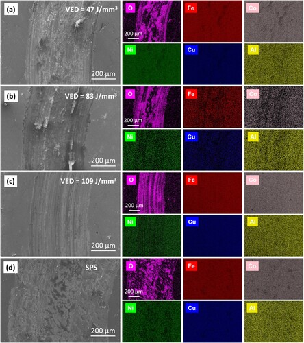
It can be found from EDS mappings ((a–c)) that the oxidation layers can be also observed on the surface of L-PBF specimens during the sliding. This means that oxidative wear is not the main factor affecting the wear mechanism. Comparing with SPS specimens, the higher hardness in L-PBF specimens leads to different wear mechanisms. It appears clearly that the wear mechanism changes from adhesive to abrasive with the increase of VED. The worn surfaces of specimens produced with 47 and 83 J/mm3 VED ((a,b)) exhibited wear debris and scars but no significant layer delamination was observed. Notice that only abrasive grooves existed in the specimen produced with 109 J/mm3 VED ((c)), implying an abrasive-dominated wear mechanism. In this situation, the oxidation layer is plowed by high hardness and large size spalling debris. This accounts for the low friction coefficients and relative high wear loss.
4. Discussion
4.1. Analysis of densification behaviour and phase composition
In general, whether or not the laser sufficiently melts the powder during L-PBF processing is the key factor in forming quality (Saedi et al. Citation2018). An appropriate VED will not only produce a larger melting pool, but also reduce the amount of porosities and then achieve higher density. The melting temperature of aluminium is much lower and its vaporisation tendency is higher than that of other elements (Dai and Gu Citation2015). All laser melted HEA specimens showed a sign of vaporisation, which was similar to the phenomena observed in L-PBF of Al–Si alloys. It is worth noting that the degree of vaporisation during L-PBF process is not related to the level of VEDs. Similar phenomena can also be found in Zhao and DebRoy’s report (Citation2001), the concentration of magnesium in the weld metal was not affected by changes in laser power.
Based on the observed microstructures and element distribution, it is believed that the L-PBF FeCoNiCuAl is composed of BCC matrix + Cu-rich B2 precipitate. This result shows that, although Cu is an FCC stabiliser, the final phase composition is mainly determined by the cooling rate during solidification. Ma, Wang, and Zeng (Citation2017) investigated the melting and solidification behaviours of L-PBF and laser cladding deposition (LCD) and pointed out that the cooling rate of L-PBF (>106 K/s) is 2–4 orders of magnitude higher than that of LCD (102–104 K/s). The melting point of Fe, Co, Ni, Cu, and Al are 1538°C, 1495°C, 1453°C, 1083°C, and 660°C, respectively. The difference in mixing enthalpy also affects the tendencies of the element segregation and partitioning. The mixing enthalpy of elements in FeCoNiCuAl HEAs is shown in (Takeuchi and Inoue Citation2005). Obviously, Cu shows a tendency to separate and form new phases, and Al has a strong segregation drive (except for Cu). Thus, the specimen produced by LCD primarily solidifies into a Fe-rich BCC dendritic region (DR) and finally solidifies into a Cu-rich FCC inter-dendritic region (ID) (Jin et al. Citation2018). During L-PBF processing, laser irradiates and melts metal powder, and then forms several melt pools of tens to hundreds of microns. Plenty of fine equiaxed grains nucleate at MPB. The coarse columnar grains are grown epitaxially along the building direction owing to the directional heat flux and thermal gradient. The unique high cooling rate of L-PBF can greatly shorten the time between the two-stage solidification, thereby effectively inhibiting the segregation of Cu and Al. However, a large amount of nanoscale Cu-rich B2 precipitates is still formed inside the matrix owing to the positive mixing enthalpy. The sluggish diffusion effects in HEA can reduce the atomic diffusion rate, and hinder the transformation of nanoscale Cu-rich precipitates from B2 phase to FCC phase (Xu et al. Citation2015). Unlike rapidly cooling in L-PBF, the SPS process has much lower cooling rates (∼7 K/s) (Mavros et al. Citation2019). Since the sintering temperature is 1000°C, the SPS FeCoNiCuAl specimen is composed of Cu-rich FCC and Al-rich BCC, as shown in Figure S4.
Table 2. The mixing enthalpy of elements in FeCoNiCuAl HEAs.
4.2. Anti-wear behaviours of the L-PBF and SPS specimens
To better understand the mechanical behaviours (elastic and plastic) of the materials, the elastic recovery (We/Wt) and plasticity (Wp/Wt) indices are used in this study. The value of We/Wt represents the amount of energy released by the material after being loaded. A higher value normally indicates a better resistance to impact loading on the materials, while the value of Wp/Wt reveals the intrinsic plasticity of the material (Zhou et al. Citation2020). A high Wp/Wt value normally denotes a high ductility and a good workability. As can be seen from (a), the specimen produced with 83 J/mm3 VED shows the highest elastic recovery index. For SPS specimen, it shows the minimum elastic recovery index owing to the dual-phase microstructure.
Figure 10. (a) Elastic recovery (We/Wt) and plasticity (Wp/Wt) indices; (b) elastic strain to failure (H/Er) and yield pressure (H2/Er3).
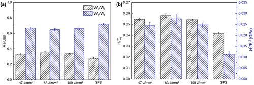
Classical wear theories (Suh Citation1973; Khruschov Citation1974; Zeng et al. Citation2018) tend to emphasise hardness as the main characteristic that determines the resistance to localised plastic deformation. Generally, materials with higher hardness usually demonstrate a high Young's modulus, which means the materials are hard to deform under a constant load (Musil et al. Citation2002). Recently, it is increasingly recognised that Young’s modulus, particularly in abrasion wear, is an equally (if not more) important factor as hardness (Moharrami et al. Citation2013; Okoro et al. Citation2019). However, it is difficult to quantitatively describe the anti-wear ability of materials by using the value of any of these factors (H and Er). Thus, the ratio of the nano hardness to the reduced elastic modulus (H/Er) and the yield pressure (H2/Er3) were introduced to further assess the anti-wear properties of the L-PBF and SPS specimens. The value of H/Er represents the elastic strain to failure, which means that the higher the value, the better the wear resistance will be. While a higher value of H2/Er3 indicates a better resistance to plastic deformation. (b) shows that the specimen produced with 83 J/mm3 VED has the highest H/Er and H2/Er3 (∼0.058 and ∼0.028 GPa), while the SPS specimen has the opposite results: it exhibits the lowest H/Er and H2/Er3 (∼0.041 and ∼0.011 GPa). This means that tribological properties of materials can be effectively adjusted by the change of VED. As mentioned earlier, high hardness can be obtained under high VED through a high cooling rate (fine grain) and severe re-melting (large precipitate). Young’s modulus is relevant to the orientation of the crystalline structure and L-PBF typically leads to directional grain growth. Therefore, it is possible to adjust the anti-wear abilities of the HEA alloy component by exposing the preferred orientation to the wearing load.
Besides, the yield pressure of SPS specimen is significantly lower than that of L-PBF specimen due to its coarse grain and dual-phase structure. The L-PBF technique provides a novel way for material processing that can be used to refine microstructures as well as adjust the Young’s modulus for improved tribological properties.
5. Conclusions
In this study, the influences of volume energy density (VED) during laser powder bed fusion (L-PBF) on the microstructure, mechanical properties, and tribological behaviour of a near-equiatomic FeCoNiCuAl High-entropy alloy were systematically investigated. Based on the experimental results, the following conclusions can be drawn:
As the VED escalates from 47 to 83 J/mm3, the relative density of the L-PBF FeCoNiCuAl HEA increases to its maximum level (∼96%), beyond which the density drops slightly. The laser-melted component consists of BCC matrix + Cu-rich B2 precipitates, which is different from SPS specimen with Cu-rich FCC and Al-rich BCC phases.
The L-PBF specimen shows a strong texture in <001> orientation at 47 J/cm3 VED. As the VED increases, the texture becomes weaker and finally converts into <101> crystallographic direction families at 109 J/cm3.
The nano hardness is gradually improved as the VED rises and the maximum nano hardness is ∼8.42 GPa. The Young's modulus of the L-PBF FeCoNiCuAl HEA exhibits strong anisotropy and the lowest modulus was found along the <001> direction, i.e. ∼142 GPa.
The L-PBF FeCoNiCuAl HEA shows a higher elastic strain to failure (H/Er) and yield stress (H2/Er3), which accounts for better wear resistance compared with SPS counterparts. The L-PBF specimen produced with 83 J/mm3 VED exhibits the highest anti-wear ability combined with low Young's modulus.
Supplemental Material
Download MS Word (1,021.8 KB)Acknowledgements
The authors would thank Sinoma Institute of Materials Research (Guang Zhou) Co., Ltd. for the assistance in TEM characterisation.
Disclosure statement
No potential conflict of interest was reported by the author(s).
Correction Statement
This article has been republished with minor changes. These changes do not impact the academic content of the article.
Additional information
Funding
Notes on contributors
Yaojia Ren
Yaojia Ren is a currently PhD candidate of Central South University.
Luxin Liang
Luxin Liang is a currently PhD candidate of Central South University.
Quan Shan
Quan Shan is an associate professor of Kunming University of Science and Technology.
Anhui Cai
Anhui Cai is a professor of Hunan Institute of Science and Technology.
Jingguang Du
Jingguang Du is a currently Master's candidate of Central South University.
Qianli Huang
Qianli Huang is an associate professor of Central South University.
Shifeng Liu
Shifeng Liu is a professor of Xi'an University of Architecture & Technology.
Xin Yang
Xin Yang is a professor of Xi'an University of Technology.
Yingtao Tian
Yingtao Tian is a lecturer of Lancaster University. His research interests focus on advanced laser processing, additive manufacturing & 3D printing, micro-fabrication, etc.
Hong Wu
Hong Wu is a professor of Central South University.
References
- Borkar, T., B. Gwalani, D. Choudhuri, C. V. Mikler, C. J. Yannetta, Xiaodong Chen, Raju Vijayaraghavan Ramanujan, M. J. Styles, M. A. Gibson, and Rajarshi Banerjee. 2016. “A Combinatorial Assessment of AlxCrCuFeNi2 (0< x < 1.5) Complex Concentrated Alloys: Microstructure, Microhardness, and Magnetic Properties.” Acta Materialia 116: 63–76.
- Chen, Z. W., M. A. L. Phan, and K. Darvish. 2017. “Grain Growth During Selective Laser Melting of a Co-Cr-Mo Alloy.” Journal of Materials Science 52 (12): 7415–7427.
- Dai, Donghua, and Dongdong Gu. 2015. “Effect of Metal Vaporization Behavior on Keyhole-Mode Surface Morphology of Selective Laser Melted Composites Using Different Protective Atmospheres.” Applied Surface Science 355: 310–319.
- Dai, Donghua, Dongdong Gu, Qing Ge, Yanze Li, Xinyu Shi, Yixuan Sun, and Shuhui Li. 2020. “Mesoscopic Study of Thermal Behavior, Fluid Dynamics and Surface Morphology During Selective Laser Melting of Ti-Based Composites.” Computational Materials Science 177: 109598.
- Dong, Jian, Ping Du, and Xin Zhang. 2013. “Characterization of the Young’s Modulus and Residual Stresses for a Sputtered Silicon Oxynitride Film Using Micro-Structures.” Thin Solid Films 545: 414–418.
- Fang, Qihong, Yang Chen, Jia Li, Yanbin Liu, and Yong Liu. 2018. “Microstructure and Mechanical Properties of FeCoCrNiNbX High-Entropy Alloy Coatings.” Physica B: Condensed Matter 550: 112–116.
- Geng, Hong Bin, Suk Bong Kang, and Bok Ki Min. 2004. “High Temperature Tensile Behavior of Ultra-Fine Grained Al-3.3Mg-0.2Sc-0.2Zr Alloy by Equal Channel Angular Pressing.” Materials Science and Engineering: A 373 (1–2): 229–238.
- George, Easo P., W. A. Curtin, and Cemal Cem Tasan. 2020. “High Entropy Alloys: A Focused Review of Mechanical Properties and Deformation Mechanisms.” Acta Materialia 188: 435–474.
- Gludovatz, Bernd, Anton Hohenwarter, Dhiraj Catoor, Edwin H. Chang, Easo P. George, and Robert O. Ritchie. 2014. “A Fracture-Resistant High-Entropy Alloy for Cryogenic Applications.” Science 345 (6201): 1153–1158.
- Han, Changjun, Qihong Fang, Yusheng Shi, Shu Beng Tor, Chee Kai Chua, and Kun Zhou. 2020a. “Recent Advances on High-Entropy Alloys for 3D Printing.” Advanced Materials: 1903855.
- Han, Changjun, Babicheva Rita, Jasper Chua Dong Qiu, Upadrasta Ramamurty, and Kun Zhou. 2020b. “Microstructure and Mechanical Properties of (TiB + TiC)/Ti Composites Fabricated in Situ via Selective Laser Melting of Ti and B4C Powders.” Additive Manufacturing: 101466.
- Herzog, Dirk, Vanessa Seyda, Eric Wycisk, and Claus Emmelmann. 2016. “Additive Manufacturing of Metals.” Acta Materialia 117: 371–392.
- Ishimoto, Takuya, Koji Hagihara, Kenta Hisamoto, Shi-Hai Sun, and Takayoshi Nakano. 2017. “Crystallographic Texture Control of Beta-Type Ti-15Mo-5Zr-3Al Alloy by Selective Laser Melting for the Development of Novel Implants with a Biocompatible low Young’s Modulus.” Scripta Materialia 132: 34–38.
- Jin, Guo, Zhaobing Cai, Yajie Guan, Xiufang Cui, Zhe Liu, Yang Li, and Meiling Dong. 2018. “High Temperature Wear Performance of Laser-Cladded FeNiCoAlCu High-Entropy Alloy Coating.” Applied Surface Science 445: 113–122.
- Joseph, Jithin, Tom Jarvis, Xinhua Wu, Nicole Stanford, Peter Hodgson, and Daniel Mark Fabijanic. 2015. “Comparative Study of the Microstructures and Mechanical Properties of Direct Laser Fabricated and Arc-Melted AlxCoCrFeNi High Entropy Alloys.” Materials Science and Engineering: A 633: 184–193.
- Joseph, Jithin, Nicole Stanford, Peter Hodgson, and Daniel Mark Fabijanic. 2017. “Understanding the Mechanical Behaviour and the Large Strength/Ductility Differences Between FCC and BCC AlxCoCrFeNi High Entropy Alloys.” Journal of Alloys and Compounds 726: 885–895.
- Karre, Rajamallu, Manish K. Niranjan, and Suhash R. Dey. 2015. “First Principles Theoretical Investigations of low Young’s Modulus Beta Ti-Nb and Ti-Nb-Zr Alloys Compositions for Biomedical Applications.” Materials Science and Engineering: C 50: 52–58.
- Khruschov, M. M. 1974. “Principles of Abrasive Wear.” Wear 28 (1): 69–88.
- Kunze, Karsten, Thomas Etter, Jürgen Grässlin, and Valery Shklover. 2015. “Texture, Anisotropy in Microstructure and Mechanical Properties of IN738LC Alloy Processed by Selective Laser Melting (SLM).” Materials Science and Engineering: A 620: 213–222.
- Li, W. P., X. G. Wang, B. Liu, Q. H. Fang, and C. Jiang. 2018. “Fracture Mechanisms of a Mo Alloyed CoCrFeNi High Entropy Alloy: In-Situ SEM Investigation.” Materials Science and Engineering: A 723: 79–88.
- Li, Zezhou, Shiteng Zhao, Robert O. Ritchie, and Marc A. Meyers. 2019. “Mechanical Properties of High-Entropy Alloys with Emphasis on Face-Centered Cubic Alloys.” Progress in Materials Science 102: 296–345.
- Long, Teng, Xiaohong Zhang, Qianli Huang, Ling Liu, Yong Liu, Junye Ren, Yong Yin, Dengke Wu, and Hong Wu. 2018. “Novel Mg-Based Alloys by Selective Laser Melting for Biomedical Applications: Microstructure Evolution, Microhardness and In Vitro Degradation Behaviour.” Virtual and Physical Prototyping 13 (2): 71–81.
- Ma, Mingming, Zemin Wang, and Xiaoyan Zeng. 2017. “A Comparison on Metallurgical Behaviors of 316L Stainless Steel by Selective Laser Melting and Laser Cladding Deposition.” Materials Science and Engineering: A 685: 265–273.
- Mao, Cong, Fangjian Zhou, Yongle Hu, Peihao Cai, Yifeng Jiang, Zhuming Bi, and Guanqing Peng. 2019. “Tribological Behavior of cBN-WC-10Co Composites for Dry Reciprocating Sliding Wear.” Ceramics International 45 (5): 6447–6458.
- Mavros, Nicholas, Taban Larimian, Javier Esqivel, Rajeev Kumar Gupta, Rodrigo Contieri, and Tushar Borkar. 2019. “Spark Plasma Sintering of Low Modulus Titanium-Niobium-Tantalum-Zirconium (TNTZ) Alloy for Biomedical Applications.” Materials & Design 183: 108163.
- Messé, O. M. D. M., R. Muñoz-Moreno, T. Illston, S. Baker, and H. J. Stone. 2018. “Metastable Carbides and Their Impact on Recrystallisation in IN738LC Processed by Selective Laser Melting.” Additive Manufacturing 22: 394–404.
- Moharrami, N., D. J. Langton, O. Sayginer, and S. J. Bull. 2013. “Why Does Titanium Alloy Wear Cobalt Chrome Alloy Despite Lower Bulk Hardness: A Nanoindentation Study?” Thin Solid Films 549: 79–86.
- Musil, J., F. Kunc, H. Zeman, and H. Poláková. 2002. “Relationships Between Hardness, Young’s Modulus and Elastic Recovery in Hard Nanocomposite Coatings.” Surface and Coatings Technology 154 (2–3): 304–313.
- Nagase, Takeshi, Tomoyuki Kakeshita, Kotaro Matsumura, Koichiro Nakazawa, Satoshi Furuya, Nobuaki Ozoe, and Katsumi Yoshino. 2019. “Development of Fe-Co-Cr-Mn-Ni-C High Entropy Cast Iron (HE Cast Iron) Available for Casting in Air Atmosphere.” Materials & Design 184: 108172.
- Okoro, Avwerosuoghene Moses, Ronald Machaka, Senzeni Sipho Lephuthing, Samuel Ranti Oke, Mary Ajimegoh Awotunde, and Peter Apata Olubambi. 2019. “Nanoindentation Studies of the Mechanical Behaviours of Spark Plasma Sintered Multiwall Carbon Nanotubes Reinforced Ti6Al4V Nanocomposites.” Materials Science and Engineering: A 765: 138320.1–138320.8.
- Oliver, Warren Carl, and George Mathews Pharr. 1992. “An Improved Technique for Determining Hardness and Elastic Modulus Using Load and Displacement Sensing Indentation Experiments.” Journal of Materials Research 7 (6): 1564–1583.
- Prashanth, K. G., B. Debalina, Z. Wang, P. F. Gostin, A. Gebert, M. Calin, U. Kuehn, M. Kamaraj, S. Scudino, and J. Eckert. 2014. “Tribological and Corrosion Properties of Al-12Si Produced by Selective Laser Melting.” Journal of Materials Research 29 (17): 2044–2054.
- Saedi, Soheil, Narges Shayesteh Moghaddam, Amirhesam Amerinatanzi, Mohammad Elahinia, and E. Haluk Karaca. 2018. “On the Effects of Selective Laser Melting Process Parameters on Microstructure and Thermomechanical Response of Ni-Rich NiTi.” Acta Materialia 144: 152–560.
- Suh, Nam P. 1973. “The Delamination Theory of Wear.” Wear 25 (1): 111–124.
- Takeuchi, Akira, and Akihisa Inoue. 2005. “Classification of Bulk Metallic Glasses by Atomic Size Difference, Heat of Mixing and Period of Constituent Elements and Its Application to Characterization of the Main Alloying Element.” Materials Transactions 46 (12): 2817–2829.
- Wang, Yin, Ruidi Li, Pengda Niu, Zhijian Zhang, Tiechui Yuan, Jiwei Yuan, and Kun Li. 2020. “Microstructures and Properties of Equimolar AlCoCrCuFeNi High-Entropy Alloy Additively Manufactured by Selective Laser Melting.” Intermetallics 120: 106746.
- Wang, Pan, Mitsuharu Todai, and Takayoshi Nakano. 2019. “Beta Titanium Single Crystal with Bone-Like Elastic Modulus and Large Crystallographic Elastic Anisotropy.” Journal of Alloys and Compounds 782: 667–671.
- Wang, Y. Morris, Thomas Voisin, Joseph T. McKeown, Jianchao Ye, Nicholas P. Calta, Zan Li, Zhi Zeng, Yin Zhang, Wen Chen, and Tien Tran Roehling. 2018. “Additively Manufactured Hierarchical Stainless Steels with High Strength and Ductility.” Nature Materials 17 (1): 63–71.
- Xia, Mujian, Dongdong Gu, Guanqun Yu, Donghua Dai, Hongyu Chen, and Qimin Shi. 2016. “Selective Laser Melting 3D Printing of Ni-Based Superalloy: Understanding Thermodynamic Mechanisms.” Science Bulletin 61 (13): 1013–1022.
- Xin, S. W., M. Zhang, T. T. Yang, Y. Y. Zhao, B. R. Sun, and T. D. Shen. 2018. “Ultrahard Bulk Nanocrystalline VNbMoTaW High-Entropy Alloy.” Journal of Alloys and Compounds 769: 597–604.
- Xiong, Z. H., S. L. Liu, S. F. Li, Y. Shi, Y. F. Yang, and R. D. K. Misra. 2019. “Role of Melt Pool Boundary Condition in Determining the Mechanical Properties of Selective Laser Melting AlSi10Mg Alloy.” Materials Science and Engineering: A 740–741: 148–156.
- Xu, X. D., Pan Liu, Sheng Guo, Akihiko Hirata, Takeshi Fujita, T. G. Nieh, C. T. Liu, and M. W. Chen. 2015. “Nanoscale Phase Separation in a fcc-Based CoCrCuFeNiAl0.5 High-Entropy Alloy.” Acta Materialia 84: 145–152.
- Yeh, J.-W., S.-K. Chen, S.-J. Lin, J.-Y. Gan, T.-S. Chin, T.-T. Shun, C.-H. Tsau, and S.-Y. Chang. 2004. “Nanostructured High-Entropy Alloys with Multiple Principal Elements: Novel Alloy Design Concepts and Outcomes.” Advanced Engineering Materials 6 (5): 299–303.
- Yin, Yong, Qianli Huang, Luxin Liang, Xiaobo Hu, Tang Liu, Yuanzhi Weng, Teng Long, Yong Liu, Qingxiang Li, and Shaoqiang Zhou. 2019. “In Vitro Degradation Behavior and Cytocompatibility of ZK30/Bioactive Glass Composites Fabricated by Selective Laser Melting for Biomedical Applications.” Journal of Alloys and Compounds 785: 38–45.
- Youssef, Khaled M., Alexander J. Zaddach, Changning Niu, Douglas L. Irving, and Carl C. Koch. 2015. “A Novel Low-Density, High-Hardness, High-Entropy Alloy with Close-Packed Single-Phase Nanocrystalline Structures.” Materials Research Letters 3 (2): 95–99.
- Yu, Wen Hui, Swee Leong Sing, Chee Kai Chua, Che-Nan Kuo, and Xue Lei Tian. 2019. “Particle-Reinforced Metal Matrix Nanocomposites Fabricated by Selective Laser Melting: A State of the Art Review.” Progress in Materials Science 104: 330–379.
- Yu, Qiang, Wei-Wei Xu, Can Cui, Xiaoguo Gong, Wei Li, Lijie Chen, Xiaoqing Li, and Levente Vitos. 2020. “Unveiling Segregation-Induced Evolution in Phase Constitution of Cu-Containing High-Entropy Alloys.” Journal of Alloys and Compounds 843: 156109.
- Zeng, Xiang, Jingang Yu, Dingfa Fu, Hui Zhang, and Jie Teng. 2018. “Wear Characteristics of Hybrid Aluminum-Matrix Composites Reinforced with Well-Dispersed Reduced Graphene Oxide Nanosheets and Silicon Carbide Particulates.” Vacuum 155: 364–375.
- Zhang, Q., H. Xu, X. H. Tan, X. L. Hou, S. W. Wu, G. S. Tan, and L. Y. Yu. 2017. “The Effects of Phase Constitution on Magnetic and Mechanical Properties of FeCoNi(CuAl)x (x = 0–1.2) High-Entropy Alloys.” Journal of Alloys and Compounds 693: 1061–1067.
- Zhao, H., and T. DebRoy. 2001. “Weld Metal Composition Change During Conduction Mode Laser Welding of Aluminum Alloy 5182.” Metallurgical and Materials Transactions B 32 (1): 163–172.
- Zhao, Danlei, Changjun Han, Yan Li, Jingjing Li, Kun Zhou, Qingsong Wei, Jie Liu, and Yusheng Shi. 2019. “Improvement on Mechanical Properties and Corrosion Resistance of Titanium-Tantalum Alloys In-Situ Fabricated via Selective Laser Melting.” Journal of Alloys and Compounds 804: 288–298.
- Zhou, Feifei, L. P. Xu, C. M. Deng, J. B. Song, and Maochuan Liu. 2020. “Nanomechanical Characterization of Nanostructured La2(Zr0.75Ce0.25)2O7 Thermal Barrier Coatings by Nanoindentation.” Applied Surface Science 505: 144585.
- Zhou, Xiaojie, Jian Zhang, Xiaomin Chen, Xu Zhang, and Mengjia Li. 2019. “Fabrication of High-Strength AZ80 Alloys via Multidirectional Forging in Air with No Need of Ageing Treatment.” Journal of Alloys and Compounds 787: 551–559.
- Zhu, Tie, Hong Wu, Rui Zhou, Ningyi Zhang, Yong Yin, Luxin Liang, Yong Liu, Jia Li, Quan Shan, and Qingxiang Li. 2020. “Microstructures and Tribological Properties of TiC Reinforced FeCoNiCuAl High-Entropy Alloy at Normal and Elevated Temperature.” Metals 10 (3): 387.