
 ?Mathematical formulae have been encoded as MathML and are displayed in this HTML version using MathJax in order to improve their display. Uncheck the box to turn MathJax off. This feature requires Javascript. Click on a formula to zoom.
ABSTRACT
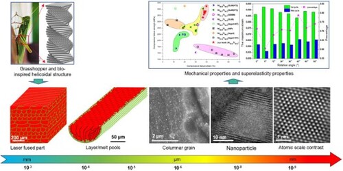
A hierarchical microstructure was obtained, including the unique interlaced dual-phase structure, the solidified molten pool, the coarse columnar B2 grains and fine equiaxed B19’ grains, and a great many nanoparticles, during laser powder bed fusion (LPBF) of NiTi alloys. The effect of laser processing parameter on the growth of nanoparticles was assessed. A combination of low laser power and high scanning speed was conducive to the formation of fine granular nanoparticles with a more uniform distribution. Subsequently, effects of rotation angle between adjacent layers on the compressive deformation behaviour of LPBF-processed NiTi alloys were studied. At a small rotation angle (6–36°), the samples could exhibit an excellent combination of high compressive fracture strength and ductility (e.g. 3094 MPa/39.85%). Meanwhile, samples with small rotation angle tended to get a large strain span for the martensite transformation stage and a large deformation capacity (e.g. 4.64% and 9.25% for θ = 6° and σmax = 800 MPa).
GRAPHICAL ABSTRACT
1. Introduction
NiTi-based shape memory alloys (SMAs) are known to exhibit unique shape memory effect and superelasticity due to a reversible martensite phase transformation (Mitchell et al. Citation2018; Ma et al. Citation2018a; Wang et al. Citation2020). This intrinsic functionality makes NiTi-based SMAs a candidate class for shock-absorbing, inflatable or actuating structures applied in aerospace, automobiles and medical implants (Li et al. Citation2016). However, poor material-processing ability during conventional processes brings about high cost and limited development of NiTi-based components (Elahinia et al. Citation2012). In recent years, NiTi SMAs, as a typical metal-based smart material, have been regaining a remarkably increasing interest, owing to the rapid development of additive manufacturing (AM)/3D printing and the emergence of 4D printing. What’s more, investigations on additive manufactured NiTi-based SMAs have stepped into a new stage where more attention is paid to the comprehensive improvement of mechanical property as well as functionality, after a long time of dedication to the densification and forming quality (Elahinia et al. Citation2016; Mahmoudi et al. Citation2018). For instance, a recent research work about 3D printed NiTi alloys has been reported in Science (Hou et al. Citation2019). High-performance low-hysteresis elastocaloric nanocomposite alloys with a typical microstructure, consisting of transforming NiTi and non-transforming Ni3Ti phases, were created by chemical composition and process control. In B. Lu’s work (Lu et al. Citation2020), columnar-to-equiaxed transition with improved superelasticity was achieved during directed energy deposited NiTi alloy, based on the addition of nanoparticle La2O3.
To enhance the mechanical property or functionality of additive manufactured components, current research interests or hotspots mainly focus on two prevailing directions, including multi-scale porous structures (Zheng et al. Citation2016; Vyatskikh et al. Citation2018; Zhu et al. Citation2018) and hierarchical microstructures (Wang et al. Citation2018b; Hou et al. Citation2019; Zhu et al. Citation2019; Gu et al. Citation2020; Lu et al. Citation2020). For instance, Zheng et al designed and fabricated a series of hierarchical metamaterials with disparate three-dimensional features spanning seven orders of magnitude, from nanometres to centimetres (Zheng et al. Citation2016). These metamaterials showed the ultrahigh tensile elasticity with two orders of magnitude higher specific tensile strength relative to the density of the lattices than Al foams and lattices (Andrews, Sanders, and Gibson Citation1999 Olurin, Fleck, and Ashby Citation2000;). In terms of hierarchical microstructures, by comparison with conventional processing technologies, AM can provide an extra hierarchy of the microstructural features – the solidified molten pool, in which condition the typical AM solidified structure includes nanoscale precipitates or dislocation structures (10−9–10−8 m), submicron-scale subgrains (∼10−7 m), micron-scale grains (10−6–10−5 m) and molten pools (10−4–10−3 m) (Wang et al. Citation2018b). Similar to large cross-scale architectures with superior properties or functions (Zheng et al. Citation2016; Vyatskikh et al. Citation2018; Zhu et al. Citation2018), hierarchical solidified structures are also able to efficiently enhance the strength and ductility of materials (Wang et al. Citation2018b; Zhu et al. Citation2019; Gu et al. Citation2020). Given the ultrafast heating/cooling rate of 103–8 K/s and the nonequilibrium metallurgical process during the laser AM (Han et al. Citation2020), the highly localised melting/solidification during AM is prone to induce the hierarchical microstructure which engenders excellent mechanical properties. Zhu et al achieved a hierarchically heterogeneous microstructure by the tailored AM process of an interstitial solute-strengthened high entropy alloy, Fe49.5Mn30Co10Cr10C0.5 (at. %), including the molten pool, cellular structures, a high density of dislocations and a few Al-rich oxides, contributing to a combination of high yield strength (∼710 MPa) and excellent uniform elongation (∼28%) (Zhu et al. Citation2019). Besides, C. Zhao et al used a series of novel in-situ technologies to monitor the laser melting process, aiming to ease the understanding for the formation of hierarchical microstructure (Zhao et al. Citation2017; Leung et al. Citation2018; Parab et al. Citation2018; Zhao et al. Citation2019). It is worth to point out that apart from an increase of the hierarchy of the microstructural features, AM also enables the tailored arrangement of laser scanned tracks, thus bringing more freedoms for the control of the solidified structure. Fewer attention has been paid to the building of hierarchical microstructures in AM, rather than to the multi-scale porous structures.
How to efficiently design and tailor hierarchical microstructures or multi-scale porous structures is another critical challenge. Bionic design may be an excellent alternative to provide a solution. Most of nature biomaterials, e.g. wood, nacre, bone, etc., have evolved through a strategy of organising three-dimensional architectures from the nano- to macroscale after thousands of years to better adapt to the nature (Zheng et al. Citation2016). These large cross-scale features existing in the nature biomaterials give the researchers a great many enlightenment. F. Bouville et al fabricated dense ceramic materials with structural features spanning several length scales, inspired by structural guidelines derived from the study of nacre (Bouville et al. Citation2014). As a result, the bioinspired ceramics showed a unique combination of high strength (470 MPa), high toughness (17.3 MPa m1/2) and high stiffness (290 GPa). Bührig-Polaczek et al designed and developed a type of biomimetic cellular metals characterised by hierarchical structures, inspired by fruit walls as well as nut and seed shells (Bührig-Polaczek et al. Citation2016). This hierarchically structured bio-inspired cellular metals exhibited a superior energy absorption capability, compared by the traditional metal foams. At present, limited investigations on hierarchical structures and their building approaches in additive manufactured NiTi SMAs have been reported.
In the exoskeletons of several crustacean (Ma et al. Citation2019) and insect (e.g. grasshopper) (Zimmermann et al. Citation2013) as well as fish scales (Naleway et al. Citation2015), the typically helicoidal structure known by Bouligand where each layer of fibres is rotated from the previous stacked layer by a constant angle and the arrangement completes a full 180̊ rotation in a period, is common to provide significant resistance to mechanical stress (Naleway et al. Citation2015). In this work, inspired by the Bouligand structure emerging in the grasshopper’s exoskeleton (Lenau and Barfoed Citation2008), we created hierarchical NiTi alloys with high strength and toughness via laser powder bed fusion (LPBF) AM approach using a bioinspired arrangement for the laser scanned tracks. Hierarchical microstructure features and mechanical behaviour of LPBF-processed NiTi alloys were studied and discussed. A fundamental understanding of the microstructure-property relationship in this work was elaborated.
2. Experimental procedure and modelling approach
2.1. Bio-inspired process design
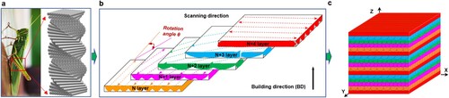
(a) shows the macro-image of grasshopper and the corresponding schematic of the Bouligand structure. To achieve the excellent mechanical properties of the Bouligand structure, the similar stacked structure could be obtained by 3D printing process using a scan strategy mimicking the arrangement of fibres in the Bouligand structure, in consideration of the forming principle of track-by-track and layer-by-layer mode, as shown in (b,c), respectively. But the individual feature of the laser-scanned track gets weakened due to the strong metallurgical bonding during the LPBF process, which makes it difficult to achieve the superior properties of the Bouligand structure. However, in this work, unique interlaced dual-phase microstructure induced by the nature of laser processing was obtained, efficiently decreasing the influence of the metallurgical bonding, which would be described and discussed in the following sections.
Figure 1. Bio-inspired process design: (a) The Bouligand structure emerging in the exoskeleton of grasshopper; (b) The laser scanning strategy mimicking the arrangement of fibres in the Bouligand structure; (c) A schematic of the helically stacked laser tracks.
2.2. LPBF fabrication process
Regularly spherical NiTi pre-alloyed powder with a particle size of 15–53 µm was used in this work ((a)). The original chemical composition of the NiTi powder is listed in . According to the data in , nominal composition of the pre-alloyed powder could be described as Ni50.6Ti49.4. A series of cylinder-shaped samples with a diameter of 4 mm and a height of 8 mm as well as box-shaped samples with a dimension of 4 mm × 4 mm × 8 mm were fabricated ((c,d)), using the SLM-150 machine developed by the Nanjing University of Aeronautics and Astronautics (NUAA) and equipped with a 500 W IPG ytterbium fibre laser, an automatic powder spreading device with flexible scraper blade, an inert argon gas circulatory protection system and an Industrial Personal Computer (IPC) system for process control. Before LPBF consolidation, the vacuum pump was run and meanwhile the argon gas was fed inside to make the O2 content in the building chamber maintain around 250 ppm. Then, during the LPBF process, a series of laser power (P = 200–375 W) and scanning speed (v = 1000–1400 mm/s) were selected to analyse the densification behaviour. The increase steps for the laser power and scanning speed were 25 W and 100 mm/s, respectively, and the rotation angle kept a constant value of 36°. Subsequently, different rotation angles, including θ = 0°, 6°, 12°, 24°, 36°, 45°, 60°, and 90° were set, to investigate the effect of rotation angle on microstructures and mechanical properties of the as-printed samples, in which case the rest of main parameters remained the same, including a laser power of 250 W, scanning speed of 1200 mm/s, layer thickness of 30 µm and hatch spacing of 60 µm.
Figure 2. The raw material and LPBF process for sample preparation: (a) and (b) NiTi pre-alloyed powder; (c) Smooth interaction between laser beam and powder bed during LPBF; (d) Bulk-form samples for microstructural analysis and compressive test.
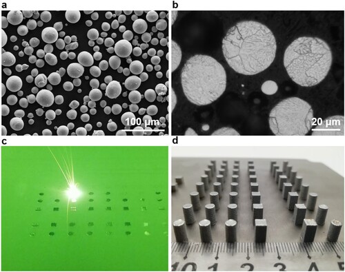
Table 1. The chemical compositions of raw NiTi pre-alloyed powder.
2.3. Microstructure characterisation and mechanical property tests
The relative densities of SLM-processed NiTi samples were evaluated based on the Archimedes method and meanwhile the image method was used to further assess the pore shape, size and distribution. The detailed microstructures were investigated using electron Backscatter Diffraction (EBSD) performed by an FEI Quanta 650 FEG FESEM (FEI. co., the U.S.A.) equipped with HKL Channel 5 system. The voltage for EBSD was 20 keV. The transmission electron microscope (TEM) and high resolution TEM (HRTEM) were carried out by using a Tecnai G2 F20 S-TWIN (operated at 200 kV) (FEI. co., the U.S.A.) to further analyse the nanoscale particles and deformation twins. The phase transformation temperature of LPBF-fabricated NiTi sample was revealed by using DSC 3 (METTLER TOLEDO, Switzerland) differential scanning calorimetry (DSC) with a heating and cooling rate of 10 °C/min from −50 °C to 150 °C. Subsequently, the compressive behaviour was studied on a CMT5205 testing machine (MTS Industrial Systems, China) at a cross-head velocity of 1 mm/min. For the compressive fracture behaviour, it was tested at a room temperature, while the testing environment was heated to Af+10 °C (Af: the martensite-to-austenite finish temperature) for the cyclic compressive behaviour. Besides, the maximum stress, the minimum stress and the cycle numbers were set as 800, 0 MPa and 10, respectively.
2.4. Modelling approach
A three-dimensional thermal-stress coupling finite element model was established, in order to disclose the role of stress distribution within the laser scanned track in the formation of dual-phase microstructure. The relative modelling parameters including thermal physical properties (e.g. thermal conductivity, the special heat capacity, coefficient of thermal expansion, etc.) and temperature-dependent mechanical properties (such as the Young modulus) of NiTi alloys, as well as the modelling size, boundary conditions and controlling equations, could be achieved from our previous work (Gu and He Citation2016). The specific description on this model was not repeated here.
In addition, the numerical simulation work on compression of helicoidal structures with various interlayer rotation angles was also performed by the static structural module in ANSYS Workbench software, to disclose the influence of rotation angle on deformation behaviour and stress distribution feature. Here, the laser scanned track was assumed to be a cylinder rod with a diameter of 70 µm, and the height of all helicoidal structures referred to that of the structure with a rotation angle of 6° where only one period existed. Hence, for the structure with 36°, it consisted of six periods. The material of helicoidal structure in this model was set as the NiTi alloys with the density of 6500 kg/m3, the Young modulus of 43 GPa and the Poisson’s ratio of 0.33 (Ma et al. Citation2019). Two rigid structural steel plates were modelled and attached to the top and bottom surfaces of the helicoidal structure, and the friction coefficient was set to 0.1. The helicoidal structure model was meshed by the program-controlled Triangle Surface Mesher and the minimum element size was 10.495 μm, while two plate models were meshed by the sweep method with the element size of 40 × 40 μm2. Then, the displacement control mode was adopted in the compression process, the bottom steel plate was fixed, and the upper steel plate moved along the direction perpendicular to the upper steel plate, with the movement speed of 1 mm/min.
3. Results
3.1. Densification evolution and phase constitution and distribution
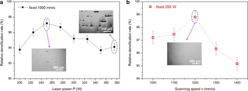
gives the evolution of the relative densification rate of the LPBF-fabricated samples at different laser processing parameters. It shows that relative densification rate firstly increased and then continuously decreased with laser power rising at a fixed scanning speed of 1000 mm/s. Excessive laser power tended to induce a plenty of interlayer pores or keyholes (Cunningham et al. Citation2019; Zhao et al. Citation2020) due to melt flow instability and severe Ni evaporation. At a fixed laser power (250 W), the relative densification rate with scanning speed increasing exhibited a similar evolution rule. High scanning speed was prone to result in insufficient liquid phase within the molten pool and attendant interlayer or intertrack metallurgical pores. The highest densification rate of 98.89% was obtained at a P of 250 W and a v of 1200 mm/s according to .
Figure 3. Effects of the applied laser powers and scan speeds on densification rates and cross-sectional microstructures of LPBF-processed NiTi alloy samples.
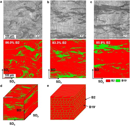
shows the XRD pattern of LPBF-processed NiTi alloy using 250 W, 1200 mm/s and rotation angle of 36°, within a wide 2θ range of 30–90°. It indicates that there only existed B2 phase and B19’ phase in the LPBF-processed NiTi alloy and B2 phase dominated. Then, (a–c) display the band contrast images (indexed areas) and the corresponding phase distribution patterns of three typical cross-sections XY, XZ and YZ of the above LPBF-processed NiTi sample, based on the EBSD characterisation. It clearly showed that there existed two different phases in the LPBF-processed NiTi sample and the red phase dominated within the microstructure, roughly reaching 83.3–86% areal fraction. Combining with the XRD result, it could be speculated that the red phase was austenite B2 phase and the green phase was martensite B19’ phase. What’s more, the B19’ phase tended to nucleate and grow along the molten pool boundaries, while the B2 phase mainly occupied the interior zones of these molten pools. Then, the three-dimensional (3D) phase distribution mapping within the sample is shown in (d). Furthermore, according to the above-mentioned features, the equivalent 3D phase distribution schematic diagram is also depicted reasonably ((e)), showing the unique interlaced dual-phase structure. It is worth noting that B2 and B19’ have different crystal structures, corresponding to CsCl type ordered structure and monoclinic structure, respectively, therefore able to trigger two different mechanical properties (Otsuka and Ren Citation2005). Normally, B2 possesses higher stiffness with ∼70 GPa elastic modulus, while the elastic modulus of B19’ is only approximately 30 GPa (Šittner et al. Citation2014). In this sense, the LPBF-processed NiTi alloys in this work could exhibit unique mechanical deformation behaviour.
Figure 4. XRD pattern of LPBF-processed NiTi alloy using a laser power of 250 W, a scan speed of 1200 mm/s and a rotation angle of 36°.
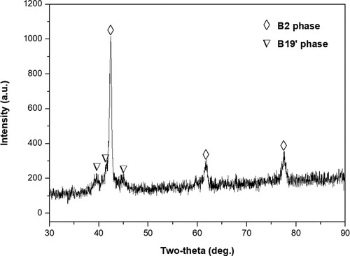
Figure 5. Distribution features of B2 and B19’ phases on three different cross-sections in LPBF-processed NiTi alloy sample: (a) XY section perpendicular to building direction (BD); (b) XZ section parallel to BD; (c) YZ section parallel to BD. X, Y and Z axials correspond to SDx, SDy and BD, respectively. The grey images are the band contrast images. (d) 3D mapping of phase distribution; (e) A schematic of the corresponding phase distribution and expanded microstructure configuration.
3.2. Grains orientation and crystallographic texture
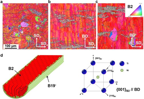
For this dual-phase microstructure, it was necessary to achieve more insights into the grain features from three different cross-sections, in order to better understand the potentially unique mechanical behaviour. (a–c) depicts the EBSD orientation image maps where the SDy was chosen as the projection axis of XY, XZ and YZ sections. For B2 phase, strong orientation texture {001}B2//BD could be observed and a great many elongated columnar grains run through several layers, which was consistent with the previously reported results (Dadbakhsh et al. Citation2016; Saedi et al. Citation2017). Different from B2 phase, B19’ phase existed with very fine equiaxed grains, showing a randomly distributed texture feature in all observed sections. According to the grain morphology and orientation of B2 and B19’ within the LPBF-fabricated NiTi sample, a characteristic microstructure within a single laser-processed track could be elaborated clearly ((d)): the interior, relatively coarse column B2 grains with dominated {001}B2 orientation along BD; the boundary, relatively fine equiaxed B19’ grains without apparent orientations.
Figure 6. EBSD orientation image maps on three different cross-sections of XY (a), XZ (b) and YZ (c) in LPBF-processed NiTi alloy sample. (d) Schematics of columnar grain growth and crystalline structure of B2 phase.
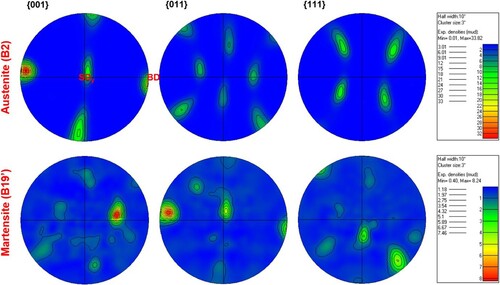
further exhibits the pole figures (PFs) of B2 and B19’ as well as the corresponding texture index in XZ cross-sections. The texture index was introduced to assess the relative texture strength of different grain orientations, which can be calculated using the following formula (Bunge Citation1993):
(1)
(1) where f is the orientation distribution and g is the Eulerspace coordinate. Normally, there exists an apparent preferred orientation when the material possesses a texture index higher than 2. Based on Equation (1), the maximum texture index nmax of B2 phase and B19’ phase in XZ section was 33.82 and 8.24, respectively, which indicated that there existed a significant orientation texture in B2 phase. As for the specific grain orientations, the strongest grain orientation {001}B2 actually oriented about 2–5° with BD in XZ section. For B19’ phase, {001}B19’ and {011}B19’ exhibited relatively apparent preferred orientations in XZ section, orienting about 45° with BD and about 5° with BD, respectively.
Figure 7. Pole figures of B2 phase (a) and B19’ phase (b) on XZ cross-section of LPBF-processed NiTi alloy sample.
3.3. Ti-rich nanoscale dispersed particles
During the high-temperature laser-based AM of NiTi alloys, an inevitable challenge is nickel evaporation due to the remarkable difference in boiling point between nickel (2732°C) and titanium (3287°C) (Lin et al. Citation2006; Sam et al. Citation2018). As a result, some Ti-rich intermetallic is often observed within the as-fabricated samples (Franco et al. Citation2017; Ma et al. Citation2017), further resulting in the change of transformation temperature/path and mechanical response behaviour. Similar to the previously reported investigations, a plenty of nanoscale particles were found to uniformly disperse within both the interior and the boundary of the molten pool in this work ((a–e)). With the help of TEM observation ((f,g)), the nanoparticle diameter was approximately estimated as 10 nm, accompanying some Moiré fringes emerging in the particle/matrix interface. By the Fast Fourier Transform (FFT), the selective area diffraction pattern (SADP) of the whole region of (h) was achieved, from which the matrix B2 and the nanoparticle Ti4Ni2O were distinctly identified. Meanwhile, the corresponding EDS point analysis of the matrix and the nanoparticle was performed and the detailed chemical compositions are displayed in . It shows that apparent oxygen constituent existed in the nanoparticle and the atomic ratio of Ti, Ni and O was just 4:2:1, verifying the SADP results. The matrix kept a Ni-rich composition, which could be able to contribute to a low transformation temperature. Furthermore, through the inverse FFT, atomically resolved images, respectively, corresponding to region C and D in (g) are presented ((i,j)). For region C (namely the matrix B2), different indices of crystallographic plane including (100) B2, (010) B2 and (110) B2 were marked, according to the calculated crystalline interplanar spacings and the JCPDS Card No.18-0899. Besides, the ordered atomic arrangement with a body centred cubic (bcc) could be easily discerned from the image ((i)) where red atom was on behalf of Ti atom and green one represented Ni atom, showing the typical austenite structure with the zone axis [00-1] B2. For the region D, the indices of crystallographic plane corresponding to (2-33) Ti4Ni2O, (422) Ti4Ni2O and (6-15) Ti4Ni2O could be confirmed based on the JCPDS Card No.72-0443, as shown in (h). The zone axis of region D was [−324] Ti4Ni2O. Hence, the orientation relationship of B2 and Ti4Ni2O could be expressed as [00-1] B2 // [−324] Ti4Ni2O. The misfit degree of crystalline interplanar spacings of (110)B2 and (422)Ti4Ni2O was 14.56%, showing a semi-coherent relationship. In consideration of the limited oxygen concentration in the raw powder and processing chamber, some of these nanoparticles might exist in the form of Ti2Ni which has the same face centred cubic (fcc) lattice and close lattice parameters as Ti4Ni2O (Meisner et al. Citation2016). The previous studies have implied that formation of Ti4Ni2O derived from the reaction between Ti2Ni and oxygen pick-up, and oxygen element could help stabilise Ti2Ni phase (Chuprina and Shalya Citation2002; Zhang, Sato, and Ishida Citation2003; Toro et al. Citation2009).
Figure 8. Nanoparticles dispersed within the LPBF-processed part. (a)–(c) Microstructure features located at the molten pool boundary (corresponding to region A in (a)); (d)–(f) Microstructure features located at the molten pool interior (corresponding to region B in (a)); (g) High-resolution TEM image of the nanoparticle with Moire fringe; (h) SADP based on FFT showing the diffraction lattices of B2 and Ti4Ni2O phase; (i) and (j) Atomically resolved images respectively corresponding to region C and D in (g).
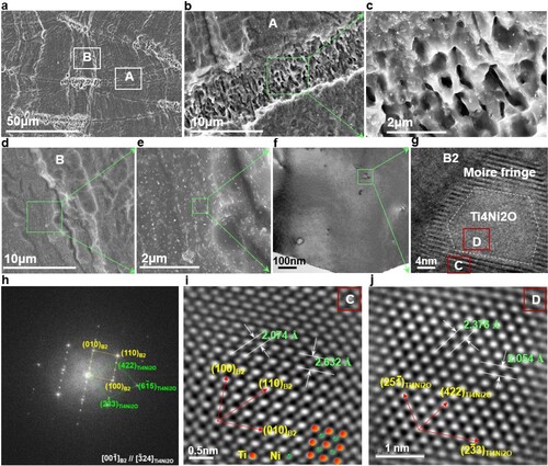
Table 2. The chemical compositions of the matrix and the precipitate in the as-fabricated NiTi sample.
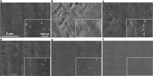
Generally, Ti4Ni2Ox phase always shows the micron scale and is regarded as the detrimental phase which can cause crack initiation due to the incoherency and weak joint with the matrix during the conventional manufacturing process (Meisner et al. Citation2016). But during the LPBF processing, the laser beam-induced nonequilibrium metallurgical behaviour contributed to the formation and uniform distribution of semi-coherent Ti4Ni2Ox nanoparticles, thus efficiently alleviating the stress concentration in the interface. Here, we further studied the influence of laser processing parameters on the morphology and distribution of Ti4Ni2Ox nanoparticles (). At a high laser power of 375 W ((a)), nanoparticles demonstrated a relatively uniform distribution and the average particle size roughly fluctuated around 80 nm. As laser power gradually decreased, nanoparticles tended to distribute along the columnar grain boundaries of the matrix, simultaneously exhibiting an apparent orientation similar to the growth direction of B2 columnar grains. At a laser power of 275 W, the morphology of nanoparticles evolved from fine granular form to coarsened dendritic shape ((c)). When the applied laser power further decreased to 250 W, the morphology of nanoparticles showed the fine granular feature again ((d)). As the laser power was fixed at 250 W, the size of nanoparticles significantly got refined and meanwhile more uniform distribution was achieved, with the laser scanning speed increasing ((d–f)).
Figure 9. Distribution and content of nanoparticles within the matrix at different laser parameters. (a) P = 375 W, v = 1000 mm/s; (b) P = 325 W, v = 1000 mm/s; (c) P = 275 W, v = 1000 mm/s; (d) P = 250 W, v = 1000 mm/s; (e) P = 250 W, v = 1100 mm/s; (f) P = 250 W, v = 1200 mm/s.
3.4. Mechanical properties
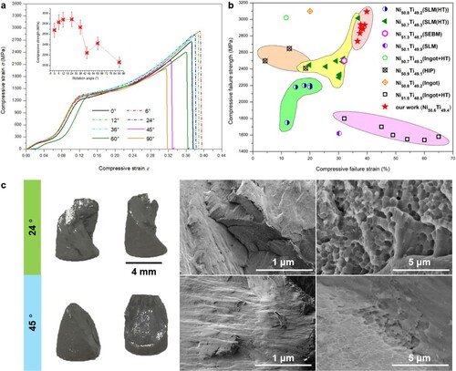
Based on the above-mentioned microstructure evolution, we found that a combination of low laser power and high laser scanning speed (e.g. 250 W–1200 mm/s) could contribute to the finer precipitate particles with a more uniform distribution. further shows the compressive fracture curves and the corresponding fracture surface morphology of LPBF-fabricated samples at 250 W–1200 mm/s but various rotation angles. Taking the fluctuation of compressive properties into consideration, three samples with the same laser processing parameter were tested during the compression. It revealed that high rotation angle was prone to inducing a low compressive fracture strength ((a)). At a relatively small rotation angle (e.g. 6–36°), the samples could exhibit an excellent combination of high compressive fracture strength (2629–3094 MPa) and good compressive fracture ductility (32.48–39.85%). In comparison with previously reported compressive properties of Ni-rich NiTi alloys fabricated by AM and conventional methods (Elahinia et al. Citation2016; Farvizi et al. Citation2016; Andani et al. Citation2017; Fan et al. Citation2017; Saedi et al. Citation2017; Zhou et al. Citation2019), our work showed a simultaneous enhancement of strength and ductility ((b)). (c) gives the fracture surface morphologies at the rotation angle of 24° and 45°, respectively. It was found that the sample with a rotation angle of 24° displayed the more complicated crack propagating path (showing a torsion-like fracture) with more small fractured surfaces, by comparing with that of the sample with 45°. In this case, more fine dimples emerged in the sample with 24°, while the fracture morphology of the sample with 45° was mainly characterised by a relatively flat surface with shallow dimples.
Figure 10. Compressive fracture behaviour of LPBF-fabricated NiTi alloy parts at different rotation angles. (a) The image showing compressive stress–strain curves, insert by a small picture displaying a plot of compressive strength–rotation angle; (b) A comparison between the mechanical properties of the LPBF-fabricated NiTi samples and other Ni-rich NiTi alloys processed by different techniques; (c) The compressive fracture surface features of the LPBF-fabricated NiTi samples with 24° and 45°.
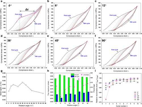
Besides, the influence of rotation angle on superelasticity properties of LPBF-fabricated Ni-rich NiTi alloys was also assessed. For the first loading–unloading cycle, the maximum irrecoverable strain was observed to exist in the sample with 6°, compared with other samples, and the maximum hysteresis loop area was obtained by the sample with 0° ((a–f)). Based on the first cycle curve, the strain span Δϵ for the martensite transformation stage, which was determined through the tangent method ((a)), was plotted as a function of rotation angle ((g)). It was found that the Δϵ for the sample with 0° or high rotation angle (e.g. 60° and 90°) was apparently lower than that for the sample with a relatively small rotation angle. The maximum Δϵ of 0.051 was obtained for the sample with 36°. (h) shows the maximum strain ϵmax (referred to the strain when the stress came to 800 MPa during the loading process) for the first and the 10th loading–unloading cycles at different rotation angles. The sample with 6° exhibited the maximum ϵmax for the first cycle and the minimum ϵmax for the 10th cycle, thus showing the largest accumulated permanent deformation, while the samples with high rotation angles displayed the lower permanent deformation. The recoverable strain ϵrev denoted the difference value between the maximum strain and the residual strain after unloading. After 10 cycles, the hysteresis loop area tended to get a steady value and the relative recoverable strain (ϵrev/ϵmax) reached a great value close to 1 for all samples ((i)). It was worth noting that the ϵrev/ϵmax still maintained a relatively low level of ∼0.95 for the sample with 0° ((f)).
Figure 11. Cyclic compressive behaviour of the LPBF-fabricated NiTi alloy parts at different rotation angles. (a)–(f) Cyclic compressive curves; (g) A plot of the strain span of the martensite transformation stage and rotation angle; (h) The maximum compressive strain at the first and 10th cycle; (i) The relative recoverable strain at different cycle numbers.
4. Discussion
4.1. LPBF developed unique interlaced dual-phase microstructure
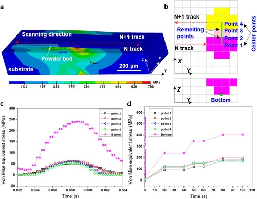
As for LPBF-fabricated Ni-rich NiTi alloys, it suggests that B2 phase dominates within the solidified microstructure in many studies including this work () (Dadbakhsh et al. Citation2015; Dadbakhsh et al. Citation2016; Saedi et al. Citation2018; Wang et al. Citation2018a). Besides, the processing parameters have significant influence on the orientation texture of the matrix phase but a limited effect on the relative diffraction intensity ratio of B2/B19’ (Saedi et al. Citation2018). According to the Ti-Ni binary phase diagram, excessive Ni is conducive to stabilise the austenite formed in LPBF with ultra-high cooling rate (Frenzel et al. Citation2010). Solved Ni atoms in B2 can significantly increase the shearing barrier of martensite transformation. On the other hand, (Nagarajan and Chattopadhyay Citation1994) found that nano-dispersions of Ti2Ni phase could form during melt spinning of NiTi alloy with 0.3 wt.% silicon due to the existence of large undercooling (ΔT/TM∼0.4) that suppresses nucleation of equilibrium phases. As for the LPBF process, stronger undercooling can be induced, accompanying remarkable Ni evaporation, thus leading to a metastable eutectic reaction of L→Ti2Ni + TiNi (Lin et al. Citation2006) and attendant mass production of nano-Ti4Ni2Ox particles. The Ti4Ni2Ox phase in return further promotes an increase of Ni content in the matrix. However, there still exists a small quantity of B19’ phase identified in the final sample, mainly distributing around the molten pool boundary, which might result from the LPBF-induced considerable thermal stress. (a) demonstrates the predicted thermal stress distribution contour within LPBF processed tracks, indicating the formation of considerable stress in the molten pool bottom. To quantitatively give the stress evolution of various positions within the molten pool, five points are selected including point 1 and point 4 at the centre position on the top surface of molten pool, point 2 and point 3 locating at the overlap zone between the N track and the N+1 track, as well as the point at the molten pool bottom ((b)). Their thermal stress developments are then displayed in (c,d). It shows that the slightly higher thermal stress can be induced in the laser overlap zone in comparison with that in the centre of laser scanned track. Meanwhile, much higher thermal stress is produced in the bottom of the molten pool during the solidification process ((c)). When the as-fabricated part gets cooled, the residual stress within the part gradually increases due to the thermal accumulation and then reaches a relatively steady value ((d)). The heterogeneous stress distribution within the molten pool mainly results from the differentiated thermal histories (including temperature, temperature gradient and cooling rate) in different positions. More remarkable constraint effect occurs in molten pool bottom or boundary, simultaneously accompanying apparently higher temperature gradient than that in the interior of the molten pool, contributing to the considerable residual stress in molten pool bottom or boundary (Du et al. Citation2018; Ma et al. Citation2018a). Based on the tangent method, the critical stress for martensite transformation of the LPBF-fabricated NiTi alloys in this work can be estimated from as 350–450 MPa, which also suggests that the residual stress in the molten pool bottom is enough to activate martensite transformation.
Figure 12. Stress field numerical simulation for the LPBF process of NiTi tracks. (a) The stress field cloud picture; (b) The schematics of heat source model showing the positions of the selected points; (c) and (d) The evolution of Von Mise equivalent stress with laser irradiation time in different time scales.
4.2. Influence of the bioinspired arrangement of laser scanned tracks
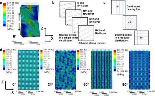
Based on the results of section 3.4, it is believed that the bioinspired arrangement of laser scanned tracks plays a crucial role in high strength/toughness and excellent fracture resistance of LPBF-processed NiTi alloys. In order to reveal the influencing mechanism of the bioinspired arrangement, the corresponding simulation work is performed. The laser scanned track is here simplified as a rod in a helicoid, from spatial construction aspects of view (as shown in (a)). shows the stress distribution contours of these helicoids with different rotation angles at the same displacement. The helical structure with a constant rotation angle of 6° is focused on first ((a)). It is found that an apparent twisting deformation occurs and stress concentration area emerges with a diagonal distribution. According to the micropolar theory (Li, Yang, and Lu Citation2019), the twisting behaviour can be attributed to the off-axial stress transfer induced by the broken centrosymmetry ((b)). As the rotation angle increases, the distribution of stress bearing points evolves from a single linear one to a reticular one ((c)), thus leading to an enhanced in-plane (x-y plane) isotropy, a more uniform stress distribution and lower stress level in the whole structure ((d)). Note that, the compression-shear coupling effect gets weakened due to the improvement of the centrosymmetry in this condition. Two special cases come from the helicoids with the rotation angles of 0° and 90° ((d)). For the former, it shows that the stress level in the whole structure is highest and the maximum stress reaches as high as 1063.8 MPa. In this case, there is no compression-shear coupling effect and the in-plane anisotropy rises to the maximum. For the latter, the stress level increases slightly, comparing with that with 60°. The compression-shear coupling effect is also absent and the isotropic in-plane stiffness is obtained for this case. Based on the above analysis, it suggests that both compression-shear coupling effect and in-plane isotropy are conducive to improve the toughness of the helicoid.
Figure 13. Numerical simulations on compressive process of stacking structures with various interlayer rotation angles. (a) The predicted stress distribution contour at the θ of 6°; (b) The distribution feature of the bearing points in the adjacent several layers for the structure with 6°; (c) The distribution feature of the bearing points for different rotation angles; (d) The predicted stress distribution contours at different rotation angles.
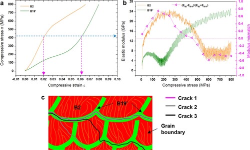
Due to the similar spatial construction, the LPBF-fabricated NiTi parts can exhibit a similar deformation behaviour. As the applied stress rises to a critical value when a crack initiates in a more compliant region (here refers to molten pool boundary region), B19’ phase is believed to play a crucial role in the propagation of the crack. According to Weaver’s work (Weaver et al. Citation2012), cracks tend to propagate between tracks rather than to severe them in a helicoidal architecture, following the path with less resistance, further resulting in a twisting crack front which creates a much larger surface area per unit crack length ((c)). During this process, an elastic modulus mismatch α = (EB2-EB19’)/(EB2+EB19’) is the key factor (Weaver et al. Citation2012). describes the deformation behaviours of the sample with the initial phase of B2 and the sample with B19’ phase. It is found that larger strain is induced in B19’ than B2 under the same stress level ((a)). During the loading process of SLM-fabricated NiTi alloys in this work, for the mesoscale molten pool (B2 phase dominates the interior, while B19’ occupies the boundary), an assumption is made that the stress condition is the same within the molten pool. Given the Young moduli of these two phases were different, the strain or deformation in B2 and B19’ was different. Hence, more detwinning and slips occur in B19’ due to its lower Young moduli, in which case the elastic modulus mismatch occurs to fluctuate as the applied load increases ((b)). When a crack initiates in the molten pool boundary, it may advance by either crossing the boundary (B19’ phase) or deflecting into boundary, which depends on the fracture toughness ratio GB19’/GB2. There exists a critical value C0, if the GB19’< C0GB2, a crack will tend to be deflected into the boundary (e.g. crack 1 in (c)); if the GB19’> C0GB2, the relative tendency of a crack to cross the boundary can occur (e.g. crack 2 in (c)). According to He and Hutchinson’s work (He and Hutchinson Citation1989), the GB19’/GB2 is proportional to (1-α)−1. Therefore, the fluctuation of the α directly brings about the change of GB19’/GB2, consequently guiding the cracks propagating circuitously and an increase of ductility (e.g. crack 3 in (c)). However, for LPBF-fabricated NiTi part with a large rotation angle (e.g. 45°), more homogenous stress distribution is obtained due to the increased bearing points and consequently the sample might exhibit a catastrophic failure once the stress reaches the critical value (Suksangpanya et al. Citation2018). Since a strong crystallographic texture {001}B2 along BD exists within B2 matrix, the close-packed plane {110}B2 , in which the dislocation slip resistance is lowest, orientates around 45° with the BD, therefore parallel to the maximum shear stress plane. For the sample with a small rotation angle, the off-axial stress transfer behaviour can change the above orientation relationship between {110}B2 and the maximum shear stress plane (Taylor et al. Citation2018), thus effectively avoiding the catastrophic failure.
Figure 14. (a) Compressive stress–strain curves of the sample with the initial phase of B2 and the sample with B19’ phase; (b) The corresponding calculated elastic modulus and modulus mismatch as a function of compressive stress; (c) The schematic of crack propagation.
The superelastic properties of LPBF-fabricated NiTi parts are also influenced significantly by the rotation angle (). For a small rotation angle (e.g. 6°), the relatively higher twisting tendency is prone to induce the local stress concentration, thus resulting in slips or twinning and a resultant increase of the irrecoverable deformation and the maximum strain ((h)). But , stress transfer direction keeps changing due to twisting deformation, consequently extending the martensite variant reorientation stage. As the rotation angle increases, more uniform stress distribution effectively decreases the slips or irreversible twinning, contributing to a decrease of the irrecoverable strain and the maximum strain. Meanwhile, weakened twisting tendency makes the martensite variant reorientation stage shrink. When the rotation angle increases to 60° or 90°, the stress distribution becomes more uniform. The overall modulus of the structure decreases apparently, consequently leading to an increase in elastic strain. Meanwhile, the elastic strain increment induced by uniform stress distribution exceeds the decrease in plastics strain induced by the decreased slips or irreversible twinning, therefore accounting for the abnormal increase in the total strain. For the cyclic loading/unloading process, the accumulated irrecoverable strain causes the minimum deformation at 10th cycle for the sample with 6°, compared with that for other samples. Although the cycle number increases, the irreversible martensite variants get reduced. As a result, the relative recoverable strain gradually increases. Besides, as for the sample with 0°, it is found that its relative recoverable strain is always the lowest after two cycles, which can be attributed to the local remarkable stress concentration ((d)).
4.3. Contribution from nanoscale particles to mechanical properties
In this work, a great many nanoscale Ti4Ni2Ox particles are found to disperse uniformly within the matrix at an optimised laser processing parameter, which is believed to play an important role in the improvement of mechanical properties of LPBF-fabricated NiTi alloys. Firstly, owing to the ultrahigh cooling rate (103-6 K/s) and oxygen pickup deriving from powder materials and the environment during LPBF processing (Li et al. Citation2020), an ordered interstitial atom O sited at (1/8, 1/8, 1/8) structure ((k)) and the supersaturated solid solution Ti(Ni) can be obtained (Takeshita et al. Citation2000), during the non-equilibrium formation process of Ti2Ni phase. Based on Lei et al’s work (Lei et al. Citation2018), interstitial atoms (e.g. O) in bcc meatal can produce a tetragonal distortion of the lattice which helps induce much larger hardening than substitutional solid-solution strengthening (e.g. Ni). The corresponding yield strength increment Δσ can be estimated as
(2)
(2) where G is the shear modulus, Δλ is the difference between the longitudinal and transverse strain of the tetragonal distortion and c is the atomic concentration of oxygen atoms. According to Finlay and Snyder’s work (Finlay and Snyder Citation1950), Δλ can be roughly considered as 0.10 for oxygen-type interstitial atom. For LPBF-fabricated NiTi alloys in this study, c is around 0.06 (). Hence, the Δσ is calculated as 81.65 MPa here.
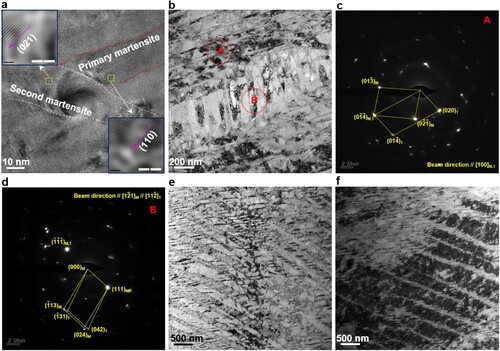
On the other hand, considering that Ti4Ni2Ox originates from the non-equilibrium nucleation process with great undercooling, Ti4Ni2Ox can exhibit a semi-coherent relationship with the matrix, namely [00-1] B2 // [−324] Ti4Ni2O (). Compared with traditional micro-scale non-coherent Ti2Ni phase, it is speculated that nanoscale Ti4Ni2Ox phase can exhibit superior strengthening effect. Here, by using the image processing technique, the volume fraction fv of nanoparticles is roughly estimated as 3.22 vol. % and the average particle size rp is approximately 7.56 nm. As a result, the particle number density ψ can reach as high as 1.78 × 10²²/m3 according to the equation of fv = (4/3)π(rp)3ψ. In this condition, the material can be strengthened significantly by the interaction between the nanoparticles and the dislocations or twinning/detwinning. During the external loading, local strain field forms around the nanoparticles due to the shearing modulus mismatch between the nanoparticle (49.4 GPa) and the matrix (B2: 10 GPa, B19’: 7.3 GPa) (Mehrabi et al. Citation2015 Toprek, Belosevic-Cavor, and Koteski Citation2015;). As shown in (a), the shearing deformation is terminated at the edge of the nanoparticle for the primary twinned martensite Mprimary. Meanwhile, another local strain field with a different orientation grows, accompanying the formation of the second detwinned martensite Msecond. As the applied stress increases, the martensite variant Msecond gets further developed. (b) shows two different groups of twin systems in another zone. Then, Msecond has exhibited a clear morphology. Based on SADP, the Mprimary contains a twinning relationship of [100]M//[100]T, while the Msecond possesses a twinning relationship of [1-21]M//[11-2]T ((c,d)). Due to the impeding effect of nanoparticles, these second twins cannot be recoverable after unloading ((e)). Besides, dislocation slips initiate and start to dominate with the accumulated strain increasing, further leading to severe dislocation pile-up ((f)) and subsequent modulus hardening. This part of strengthening contribution τcF from modulus hardening can be calculated according to the following equation (Nembach Citation1983):
(3)
(3)
(4)
(4) where CF is a constant (about 1.4), ΔG is the difference between the shearing modulus of the matrix and the nanoparticle, b is the Burgers vector, α and β are also constants, S is the dislocation line tension, t is the ratio of the outer to the inner cut-off radius of the curved dislocation and ν is the Poisson’s ratio. The result can reach as high as 749 MPa. It implies that this strengthening mode dominates in the enhancement of mechanical properties of the material.
Figure 15. TEM characterisation. (a) The impeding effect of the nanoparticle on martensite transformation and the surrounding strain field; (b) The developed second detwinned martensite variant; (c) and (d) The SADPs corresponding to regions A and B in (b); (e) and (f). The development of dislocations within the detwinned martensite.
Furthermore, either the ordered interstitial O atom structure or the modulus mismatch makes internal strain field become more complicated, thus resulting in a delay of martensite variant reorientation stage and resultant better ductility.
5. Conclusions
In this study, we fabricated a NiTi alloy with a hierarchical microstructure via LPBF technology. The hierarchical microstructure typically contained a meso-scale interlaced dual-phase structure and a nanoscale oxide phase-decorated nanostructure. To achieve the excellent mechanical properties of Bouligand structure in the grasshopper’s exoskeleton, the bioinspired scan strategy by mimicking the arrangement of fibres in the Bouligand structure was set. In this case, the effect of rotation angle between adjacent layers on the mechanical properties of LPBF-fabricated NiTi alloy parts was studied. The following conclusions could be drawn:
The unique interlaced dual-phase microstructure, containing the coarsening columnar B2 grains within the molten pool interior and the fine equiaxed B19’ grains in the molten pool boundary, was obtained after LPBF, which could be attributed to heterogeneous thermal stress distribution.
Due to strong undercooling and remarkable Ni evaporation during LPBF, the semi-coherent Ti4Ni2Ox nanoparticles formed massively, exhibiting an orientation relationship of [00-1] B2 // [−324] Ti4Ni2O with the matrix. By the image processing technique, the particle number density ψ could reach as high as 1.78 × 10²² /m3. A combination of low laser power and high laser scanning speed could contribute to the finer particles with a more uniform distribution.
At a small rotation angle (6–36°), the samples could exhibit an excellent combination of high compressive fracture strength (2629–3094 MPa) and good compressive fracture ductility (32.48–39.12%). The enhanced strength was mainly ascribed to the modulus hardening induced by modulus mismatch between the matrix and the precipitate, while an increase of ductility derives from off-axial stress transfer behaviour, twisting crack propagation and a delay of martensite variant reorientation stage.
During the cyclic compressive process, the sample with small rotation angle tended to initially exhibit a lower relative recoverable strain but a larger deformation capacity, comparing the sample with a high rotation angle. With the cyclic number increasing, the accumulated irrecoverable strain in the sample with small rotation angle firstly reached steady.
Acknowledgements
This work was supported by the financial support from the National Natural Science Foundation of China (No. U1930207 and No. 51735005), National Key Research and Development Program ‘Additive Manufacturing and Laser Manufacturing’ (Nos. 2016YFB1100101, 2018YFB1106302), National Natural Science Foundation of China for Creative Research Groups (grant number 51921003), The 15th Batch of ‘Six Talents Peaks’ Innovative Talents Team Program ‘Laser Precise Additive Manufacturing of Structure-Performance Integrated Lightweight Alloy Components’ (No. TD-GDZB-001) (Jiangsu Provincial Department of Human Resources and Social Security of China), 2017 Excellent Scientific and Technological Innovation Teams of Universities in Jiangsu ‘Laser Additive Manufacturing Technologies for Metallic Components’ (Jiangsu Provincial Department of Education of China) and the Priority Academic Program Development of Jiangsu Higher Education Institutions.
Disclosure statement
No potential conflict of interest was reported by the author(s).
Additional information
Funding
Notes on contributors
Dongdong Gu
Dongdong Gu is currently a Full Professor in College of Materials Science and Technology, Nanjing University of Aeronautics and Astronautics (NUAA), PR China.
Chenglong Ma
Chenglong Ma is currently a Lecturer in School of Mechanical Engineering, Jiangnan University, PR China.
Donghua Dai
Donghua Dai is currently a Lecturer in College of Materials Science and Technology, Nanjing University of Aeronautics and Astronautics (NUAA), PR China.
Jiankai Yang
Jiankai Yang, is currently a PhD student in College of Materials Science and Technology, Nanjing University of Aeronautics and Astronautics (NUAA), PR China.
Kaijie Lin
Kaijie Lin is currently a Lecturer in College of Materials Science and Technology, Nanjing University of Aeronautics and Astronautics (NUAA), PR China.
Hongmei Zhang
Hongmei Zhang is currently a PhD student in College of Materials Science and Technology, Nanjing University of Aeronautics and Astronautics (NUAA), PR China.
Han Zhang
Han Zhang is currently a PhD student in College of Materials Science and Technology, Nanjing University of Aeronautics and Astronautics (NUAA), PR China.
References
- Andani, M. T., S. Saedi, A. S. Turabi, M. R. Karamooz, C. Haberland, H. E. Karaca, and M. Elahinia. 2017. “Mechanical and Shape Memory Properties of Porous Ni50.1Ti49.9 Alloys Manufactured by Selective Laser Melting.” Journal of the Mechanical Behavior of Biomedical Materials 68: 224–231.
- Andrews, E., W. Sanders, and L. J. Gibson. 1999. “Compressive and Tensile Behaviour of Aluminum Foams.” Materials Science and Engineering A 270: 113–124.
- Bouville, F., E. Maire, S. Meille, B. Van de Moortèle, A. J. Stevenson, and S. Deville. 2014. “Strong, Tough and Stiff Bioinspired Ceramics from Brittle Constituents.” Nature Materials 13: 508–514.
- Bunge, H. J. 1993. Texture Analysis in Materials Science. Mathematical Methods. Göttingen: Cuvillier Verlag.
- Bührig-Polaczek, A., C. Fleck, T. Speck, P. Schüler, S. F. Fischer, M. Caliaro, and M. Thielen. 2016. “Biomimetic Cellular Metals – Using Hierarchical Structuring for Energy Absorption.” Bioinspiration & Biomimetics 11: 045002.
- Chuprina, V. G., and I. M. Shalya. 2002. “Reactions of TiNi with Oxygen.” Powder Metallurgy and Metal Ceramics 41: 85–89.
- Cunningham, R., C. Zhao, N. Parab, C. Kantzos, J. Pauza, K. Fezzaa, T. Sun, and A. D. Rollett. 2019. “Keyhole Threshold and Morphology in Laser Melting Revealed by Ultrahigh-Speed X-Ray Imaging.” Science 363: 849–852.
- Dadbakhsh, S., M. Speirs, J.-P. Kruth, and J. V. Humbeeck. 2015. “Influence of LPBF on Shape Memory and Compression Behaviour of NiTi Scaffolds.” CIRP Annals – Manufacturing Technology 64: 209–212.
- Dadbakhsh, S., B. Vrancken, J.-P. Kruth, J. Luyten, and J. V. Humbeeck. 2016. “Texture and Anisotropy in Selective Laser Melting of NiTi Alloy.” Materials Science & Engineering A 650: 225–232.
- Du, L., D. D. Gu, D. H. Dai, Q. M. Shi, C. L. Ma, and M. J. Xia. 2018. “Relation of Thermal Behavior and Microstructure Evolution During Multi-Track Laser Melting Deposition of Ni-Based Material.” Optics & Laser Technology 108: 207–217.
- Elahinia, M. H., M. Hashemi, M. Tabesh, and S. B. Bhaduri. 2012. “Manufacturing and Processing of NiTi Implants: a Review.” Progress in Material Science 57: 911–946.
- Elahinia, M., N. S. Moghaddam, M. T. Andani, A. Amerinatanzi, B. A. Bimber, and R. F. Hamilton. 2016. “Fabrication of NiTi Through Additive Manufacturing: A Review.” Progress in Materials Science 83: 630–663.
- Fan, Q. C., Y. H. Zhang, Y. Y. Wang, M. Y. Sun, Y. T. Meng, S. K. Huang, and Y. H. Wen. 2017. “Influences of Transformation Behavior and Precipitates on the Deformation Behavior of Ni-Rich NiTi Alloys.” Materials Science and Engineering: A 700: 269–280.
- Farvizi, M., M. R. Akbarpour, D.-H. Ahn, and H. S. Kim. 2016. “Compressive Behavior of NiTi-Based Composites Reinforced with Alumina Nanoparticles.” Journal of Alloys and Compounds 688: 803–807.
- Finlay, W. L., and J. A. Snyder. 1950. “Effects of Three Interstitial Solutes (Nitrogen, Oxygen, and Carbon) on the Mechanical Properties of High-Purity, Alpha Titanium.” Transactions AIME- Journal of Metals 188: 277–286.
- Franco, B. E., J. Ma, B. Loveall, G. A. Tapia, K. Karayagiz, J. Liu, A. Elwany, R. Arroyave, and I. Karaman. 2017. “A Sensory Material Approach for Reducing Variability in Additively Manufactured Metal Parts.” Scientific Reports 7: 3604.
- Frenzel, J., E. P. George, A. Dlouhy, C. Somsen, M. F.-X. Wagner, and G. Eggeler. 2010. “Influence of Ni on Martensitic Phase Transformations in NiTi Shape Memory Alloys.” Acta Materialia 58: 3444–3458.
- Gu, D., H. Chen, D. Dai, C. Ma, H. Zhang, K. Lin, L. Xi, et al. 2020. “Carbon Nanotubes Enabled Laser 3D Printing of High-Performance Titanium with Highly Concentrated Reinforcement.” IScience 23: 101498.
- Gu, D. D., and B. B. He. 2016. “Finite Element Simulation and Experimental Investigation of Residual Stresses in Selective Laser Melted Ti-Ni Shape Memory Alloy.” Computational Materials Science 117: 221–232.
- Han, C., Q. Fang, Y. Shi, S. B. Tor, C. K. Chua, and K. Zhou. 2020. “Recent Advances on High-Entropy Alloys for 3D Printing.” Advanced Materials 32: 1903855.
- He, M. Y., and J. W. Hutchinson. 1989. “Crack Deflection at an Interface Between Dissimilar Elastic Materials.” International Journal of Solids and Structures 25: 1053–1067.
- Hou, H., E. Simsek, T. Ma, N. S. Johnson, S. Qian, C. Cissé, D. Stasak, et al. 2019. “Fatigue-Resistant High-Performance Elastocaloric Materials Via Additive Manufacturing.” Science 366: 1116–1121.
- Lei, Z., X. Liu, Y. Wu, H. Wang, S. Jiang, S. Wang, X. Hui, et al. 2018. “Enhanced Strength and Ductility in a High-Entropy Alloy Via Ordered Oxygen Complexes.” Nature 563: 546–550.
- Lenau, T., and M. Barfoed. 2008. “Colours and Metallic Sheen in Beetle Shells – A Biomimetic Search for Material Structuring Principles Causing Light Interference.” Advanced Engineering Materials 10: 299–314.
- Leung, C. L. A., S. Marussi, R. C. Atwood, M. Towrie, P. J. Withers, and P. D. Lee. 2018. “In Situ X-Ray Imaging of Defect and Molten Pool Dynamics in Laser Additive Manufacturing.” Nature Communications 9: 1355.
- Li, S., H. Hassanin, M. M. Attallah, N. J. E. Adkins, and K. Essa. 2016. “The Development of TiNi-Based Negative Poisson’s Ratio Structure Using Selective Laser Melting.” Acta Materialia 105: 75–83.
- Li, X., Z. Yang, and Z. Lu. 2019. “Design 3D Metamaterials with Compression-Induced-Twisting Characteristics Using Shear–Compression Coupling Effects.” Extreme Mechanics Letters 29: 100471.
- Li, J., X. Zhou, M. Brochu, N. Provatas, and Y. F. Zhao. 2020. “Solidification Microstructure Simulation of Ti-6Al-4V in Metal Additive Manufacturing: A Review.” Additive Manufacturing 31: 100989.
- Lin, X., T. M. Yue, H. O. Yang, and W. D. Huang. 2006. “Microstructure and Phase Evolution in Laser Rapid Forming of a Functionally Graded Ti–Rene88DT Alloy.” Acta Materialia 54: 1901.
- Lu, B., X. Cui, W. Ma, M. Dong, Y. Fang, X. Wen, G. Jin, and D. Zeng. 2020. “Promoting the Heterogeneous Nucleation and the Functional Properties of Directed Energy Deposited NiTi Alloy by Addition of La2O3.” Additive Manufacturing 33: 101150.
- Ma, J., B. Franco, G. Tapia, K. Karayagiz, L. Johnson, J. Liu, R. Arroyave, I. Karaman, and A. Elwany. 2017. “Spatial Control of Functional Response in 4D-Printed Active Metallic Structures.” Scientific Reports 7: 46707.
- Ma, C., D. Gu, D. Dai, M. Xia, and H. Chen. 2018a. “Selective Growth of Ni4Ti3 Precipitate Variants Induced by Complicated Cyclic Stress During Laser Additive Manufacturing of NiTi-Based Composites.” Materials Characterization 143: 191–196.
- Ma, C. L., D. D. Gu, D. H. Dai, H. M. Zhang, L. Du, and H. Zhang. 2018b. “Development of Interfacial Stress During Selective Laser Melting of TiC Reinforced TiAl Composites: Influence of Geometric Feature of Reinforcement.” Materials & Design 157: 1–11.
- Ma, C., D. Gu, K. Lin, D. Dai, M. Xia, J. Yang, and H. Wang. 2019. “Selective Laser Melting Additive Manufacturing of Cancer Pagurus’s Claw Inspired Bionic Structures with High Strength and Toughness.” Applied Surface Science 469: 647–656.
- Mahmoudi, M., G. Tapia, B. Franco, J. Ma, R. Arroyave, I. Karaman, and A. Elwany. 2018. “On the Printability and Transformation Behavior of Nickel-Titanium Shape Memory Alloys Fabricated Using Laser Powder-bed Fusion Additive Manufacturing.” Journal of Manufacturing Processes 35: 672–680.
- Mehrabi, R., M. T. Andani, M. Kadkhodaei, and M. Elahinia. 2015. “Experimental Study of NiTi Thin-Walled Tubes Under Uniaxial Tension, Torsion, Proportional and Non-Proportional Loadings.” Experimental Mechanics 55: 1151–1164.
- Meisner, L. L., A. B. Markov, D. I. Proskurovsky, V. P. Rotshtein, G. E. Ozur, S. N. Meisne, E. V. Yakovlev, T. M. Poletika, S. L. Girsova, and V. O. Semin. 2016. “Effect of Inclusions on Cratering Behavior in TiNi Shape Memory Alloys Irradiated with a Low-Energy, High-Current Electron Beam.” Surface and Coatings Technology 302: 495–506.
- Mitchell, A., U. Lafont, M. Hołyńska, and C. Semprimoschnig. 2018. “Additive Manufacturing – A Review of 4D Printing and Future Applications.” Additive Manufacturing 24: 606–626.
- Nagarajan, R., and K. Chattopadhyay. 1994. “Intermetallic Ti2Ni/TiNi Nanocomposite by Rapid Solidification.” Acta Metallurgica et Materialia 42: 947–958.
- Naleway, S. E., M. M. Porter, J. McKittrick, and M. A. Meyers. 2015. “Structural Design Elements in Biological Materials: Application to Bioinspiration.” Advanced Materials 27: 5455–5476.
- Nembach, E. 1983. “Precipitation Hardening Caused by a Difference in Shearing Modulus Between Particle and Matrix.” Physica Status Solidi 78: 571–581.
- Olurin, O. B., N. A. Fleck, and M. F. Ashby. 2000. “Deformation and Fracture of Aluminium Foams.” Materials Science and Engineering A 291: 136–146.
- Otsuka, K., and X. Ren. 2005. “Physical Metallurgy of Ti-Ni-Based Shape Memory Alloys.” Progress in Materials Science 50: 511–678.
- Parab, N. D., C. Zhao, R. Cunningham, L. I. Escano, K. Fezzaa, W. Everhart, A. D. Rollett, L. Chen, and T. Sun. 2018. “Ultrafast X-Ray Imaging of Laser–Metal Additive Manufacturing Processes.” Journal of Synchrotron Radiation 25: 1467–1477.
- Saedi, S., N. S. Moghaddam, A. Amerinatanzi, M. Elahinia, and H. E. Karaca. 2018. “On the Effects of Selective Laser Melting Process Parameters on Microstructure and Thermomechanical Response of Ni-Rich NiTi.” Acta Materialia 144: 552–560.
- Saedi, S., A. S. Turabi, M. T. Andani, N. S. Moghaddam, M. Elahinia, and H. E. Karaca. 2017. “Texture, Aging, and Superelasticity of Selective Laser Melting Fabricated Ni-Rich NiTi Alloys.” Materials Science & Engineering A 686: 1–10.
- Sam, J., B. Franco, J. Ma, I. Karaman, A. Elwany, and J. H. Mabe. 2018. “Tensile Actuation Response of Additively Manufactured Nickel-Titanium Shape Memory Alloys.” Scripta Materialia 146: 164–168.
- Suksangpanya, N., N. A. Yaraghi, R. B. Pipes, D. Kisailus, and P. Zavattieri. 2018. “Crack Twisting and Toughening Strategies in Bouligand Architectures.” International Journal of Solids and Structures 150: 83–106.
- Šittner, P., L. Heller, J. Pilch, C. Curfs, T. Alonso, and D. Favier. 2014. “Young’s Modulus of Austenite and Martensite Phases in Superelastic NiTi Wires.” Journal of Materials Engineering and Performance 23: 2303–2314.
- Takeshita, H. T., H. Tanaka, N. Kuriyama, T. Sakai, I. Uehara, and M. Haruta. 2000. “Hydrogenation Characteristics of Ternary Alloys Containing Ti4Ni2X (X = O, N, C).” Journal of Alloys and Compounds 311: 188–193.
- Taylor, S. L., A. J. Ibeh, A. E. Jakus, R. N. Shah, and D. C. Dunand. 2018. “NiTi-Nb Micro-Trusses Fabricated via Extrusion-Based 3D-Printing of Powders and Transient-Liquid-Phase Sintering.” Acta Biomaterialia 76: 359–370.
- Toprek, D., J. Belosevic-Cavor, and V. Koteski. 2015. “Ab Initio Studies of the Structural, Elastic, Electronic and Thermal Properties of NiTi2 Intermetallic.” Journal of Physics and Chemistry of Solids 85: 197–205.
- Toro, A., F. Zhou, M. H. Wu, W. V. Geertruyden, and W. Z. Misiolek. 2009. “Characterization of Non-Metallic Inclusions in Superelastic NiTi Tubes.” Journal of Materials Engineering and Performance 18: 448–458.
- Vyatskikh, A., S. Delalande, A. Kudo, X. Zhang, C. M. Portela, and J. R. Greer. 2018. “Additive Manufacturing of 3D Nano-Architected Metals.” Nature Communications 9: 593.
- Wang, X., M. Speirs, S. Kustov, B. Vrancken, X. Li, J.-P. Kruth, and J. V. Humbeeck. 2018a. “Selective Laser Melting Produced Layer-Structured NiTi Shape Memory Alloys with High Damping Properties and Elinvar Effect.” Scripta Materialia 146: 246–250.
- Wang, Y. M., T. Voisin, J. T. McKeown, J. Ye, N. P. Calta, Z. Li, Z. Zeng, et al. 2018b. “Additively Manufactured Hierarchical Stainless Steels with High Strength and Ductility.” Nature Materials 17: 63.
- Wang, X., J. Yu, J. Liu, L. Chen, Q. Yang, H. Wei, J. Sun, et al. 2020. “Effect of Process Parameters on the Phase Transformation Behavior and Tensile Properties of NiTi Shape Memory Alloys Fabricated by Selective Laser Melting.” Additive Manufacturing 36: 101545.
- Weaver, J. C., G. W. Milliron, A. Miserez, K. Evans-Lutterodt, S. Herrera, I. Gallana, W. J. Mershon, et al. 2012. “The Stomatopod Dactyl Club: A Formidable Damage-Tolerant Biological Hammer.” Science 336: 1275–1281.
- Zhang, J. X., M. Sato, and A. Ishida. 2003. “On the Ti2Ni Precipitates and Guinier–Preston Zones in Ti-Rich Ti–Ni Thin Films.” Acta Materialia 51: 3121–3130.
- Zhao, C., K. Fezzaa, R. W. Cunningham, H. Wen, F. D. Carlo, L. Chen, A. D. Rollett, and T. Sun. 2017. “Real-Time Monitoring of Laser Powder Bed Fusion Process Using High-Speed X-Ray Imaging and Diffraction.” Scientific Reports 7: 3602.
- Zhao, C., Q. Guo, X. Li, N. Parab, K. Fezzaa, W. Tan, L. Chen, and T. Sun. 2019. “Bulk-Explosion-Induced Metal Spattering During Laser Processing.” Physical Review X 9: 021052.
- Zhao, C., N. D. Parab, X. Li, K. Fezzaa, W. Tan, A. D. Rollett, and T. Sun. 2020. “Critical Instability at Moving Keyhole Tip Generates Porosity in Laser Melting.” Science 370: 1080–1086.
- Zheng, X., W. Smith, J. Jackson, B. Moran, H. Cui, D. Chen, J. Ye, et al. 2016. “Multiscale Metallic Metamaterials.” Nature Materials 15: 1100.
- Zhou, Q., M. D. Hayat, G. Chen, S. Cai, X. Qu, H. Tang, and P. Cao. 2019. “Selective Electron Beam Melting of NiTi: Microstructure, Phase Transformation and Mechanical Properties.” Materials Science & Engineering A 744: 290–298.
- Zhu, Z. G., X. H. An, W. J. Lu, Z. M. Li, F. L. Ng, X. Z. Liao, U. Ramamurty, S. M. L. Nai, and J. Wei. 2019. “Selective Laser Melting Enabling the Hierarchically Heterogeneous Microstructure and Excellent Mechanical Properties in an Interstitial Solute Strengthened High Entropy Alloy.” Materials Research Letters 7: 453–459.
- Zhu, C., Z. Qi, V. A. Beck, M. Luneau, J. Lattimer, W. Chen, M. A. Worsley, J. C. Ye, E. B. Duoss, and C. M. Spadaccini. 2018. “Toward Digitally Controlled Catalyst Architectures: Hierarchical Nanoporous Gold via 3D Printing.” Science Advance 4: 9459–9490.
- Zimmermann, E. A., B. Gludovatz, E. Schaible, N. K. N. Dave, W. Yang, M. A. Meyers, and R. O. Ritchie. 2013. “Mechanical Adaptability of the Bouligand-Type Structure in Natural Dermal Armour.” Nature Communications 4: 2634.