
 ?Mathematical formulae have been encoded as MathML and are displayed in this HTML version using MathJax in order to improve their display. Uncheck the box to turn MathJax off. This feature requires Javascript. Click on a formula to zoom.
ABSTRACT
Selective laser-melted (SLMed) 7075 aluminium alloy is prone to cracking. Erbium (Er) could modify the aluminium alloys to prevent cracking in traditional manufacturing processes. In the present study, Er-modified 7075 aluminium alloy powders are prepared to investigate the influence of Er element on crack reduction in SLM. The evolution of Er is characterised by a scanning electron microscope (SEM), a X-ray diffraction (XRD) and high-resolution transmission electron microscope (HRTEM). The results show that the crack density is reduced with Er addition, but the porosity increases, a new discovery. Based on the SEM and TEM results, Er addition exists in the form of unmelted particles and Al3Er of sub-micrometer scale. The Er particles in the molten pool deteriorate the fluidity and result in higher porosity. The coherency between aluminium matrix and Al3Er favours the grain refinement, therefore the crack reduction.
1. Introduction
High-performance, lightweight alloys have become an integral component of the modern strategies for sustainable development (Shuai et al. Citation2019; Yang et al. Citation2019; Sing et al. Citation2021b). 7××× series aluminium alloys have become popular in aerospace, automobile, and military industries due to their low density, high specific strength, and good corrosion resistance (Heinz et al. Citation2000; Zhang et al. Citation2019). With the rapid development in these industries, the requirements for complex and integral products, which are difficult to be achieved by traditional manufacturing processes (Prashanth et al. Citation2014; Rodriguez-Salvador and Ruiz-Cantu Citation2019; Yu et al. Citation2019; Chen et al. Citation2020; Greco et al. Citation2020; Zolfagharian et al. Citation2020; Nadammal et al. Citation2021), are dramatically more demanding. Recently, selective laser melting (SLM), a powder bed fusion (PBF) additive manufacturing process (Martinez, Todd, and Mumtaz Citation2019), has been a potential technique to accelerate material innovation because SLM allows rapid fabrication with high design freedom for part complexity (Murr et al. Citation2012; Ding and Wang Citation2017; Liu et al. Citation2020; Sing et al. Citation2021a). In the past decades, considerable research efforts were devoted to adopting SLM in fabricating various aluminium (Al) alloy products (Cai et al. Citation2015; Li et al. Citation2020; Zhang et al. Citation2020; Hu et al. Citation2021). Indeed, remarkable achievements have been made in near eutectic Al-Si series alloys with fabrication of highly dense parts (Trevisan et al. Citation2017; Wenhui et al. Citation2019; Salmi and Atzeni Citation2020; Wu et al. Citation2020). However, the uptake of SLM in the fabrication of 7××× series wrought alloys was hindered by many technical problems. Apart from the intrinsic features of aluminium alloys, such as low laser energy absorption rate, high thermal conductivity and high susceptibility to oxidation (Stojanovic, Мilan, and Epler Citation2018; Lei et al. Citation2019), 7××× series alloys are less friendly to the SLM technique due to their high hot-tearing susceptibility. Diminishing defects, especially absence of cracking in high-strength aluminium alloys processed with SLM, are significantly important.
In recent years, significant efforts are upon parameter and alloying chemical optimisation to overcome the obstacles. Liu et al. (Citation2018) investigated the influence of laser parameters on single tracks of 7075 aluminium alloy fabricated with SLM, to establish the correlation between the process parameters and the continuity and dimensional uniformity. Kaufmann et al. (Citation2016) explored a wide range of process parameters to optimise the process in terms of optimum volume density. Even though the reported relative density was over 99%, all the laser-melted parts exhibited hot cracks. Qi et al. (Citation2017) investigated the effect of different melting modes on SLM defects formed 7050 aluminium alloy parts by varying the scanning speed and defocusing distance. In their research, the keyhole mode was demonstrated to effectively reduce the cracking density of the specimens, even though complete elimination was not achieved.
Although the optimisation of processing parameters has improved the SLM processability of 7××× series alloys as far as possible, it remains insufficient because of the limitation of material properties. Therefore, it is of necessity to investigate altering the compositions of materials. Different elements additions based on varying principles have been studied. In Otani and Sasaki (Citation2020), different amounts of Si addition into 7075 aluminium alloy achieved a significant advancement of the microstructure and mechanical properties. 5 w.t. % Si additions help to suppress crack and increase tensile strength to 537 MPa and ductility to 9.7%. Crack inhibition by the Si element was believed to be due to a reduction in thermal expansion, which further suppresses the driving forces of cracking. Grain refinement has been another effective way in various aluminium alloys for diminishing defects and improving mechanical properties. Qbau et al. (Citation2020) reported that 0.15 w.t. % Sc addition in AA6061 aluminium alloy allows a reduced crack generation and an increase in ultimate tensile strength to ∼ 350 MPa with a high elongation of 31%. Croteau et al. (Citation2018) elucidated the dual roles of Al3Zr sub-micrometer particles and nano-precipitates in SLMed Al-Mg-Zr ternary alloy. Tan et al. (Citation2021) inoculated the 7075 alloy powder with 1 w.t.% Ti submicron particles, which refined the aluminium grains, showing a significant increase in the cracking resistance. These results are based on the fact that the L12 structured compounds, such as Al3Sc, Al3Zr, Al3Ti, share a similar lattice structure with aluminium, allowing equiaxial and refined grains and therefore preventing cracking (Martin et al. Citation2017).
To the authors' best knowledge of the authors, Sc is the most promising and effective element to improve the processability of aluminium alloys. However, as a costly alloying element, Sc finds limited applications in industry, making it urgent and necessary to find alternatives. Er, which shows a price advantage over Sc, can form L12 structured Al3Er phase (Wen et al. Citation2011). Extensive research on the influence of Er on the microstructure and mechanical properties of aluminium alloy has been reported in traditional processing, such as casting and laser processing. Xing et al. (Citation2010) investigated the properties and microstructure of eutectic Al-12.6 w.t.% Si alloys with various contents of the rare earth element Er by the conventional casting technique. Improved anti-wear properties and reduced friction coefficient of the alloys were found due to the grain refinement. Wang, Xu, and Pan (Citation2018) verified the coherent/semi-coherent relationship between Al3Er of 20–30 nm and aluminium matrix in Er-modified 5052 alloys in continuous casting, hot-rolled, cold-rolled and annealed state. Jia et al. (Citation2018) investigated AlScZr and AlErZr alloys with laser remelting. They found that the generation of a small amount of Al3(Er, Zr) precipitation contributed to improving hardness. Laser surface remelting in Jia et al. (Citation2018) is a technique similar to SLM, thus showing the possibility of the effectiveness of Er in SLM. However, there is a limited investigation of Er-modified aluminium alloy fabricated with SLM (Hu et al. Citation2012; DebRoy et al. Citation2018).
In the present study, Er is mechanically mixed with 7075 alloy powders to investigate the influence of Er addition on the defects of SLMed 7075 aluminium alloy. It is believed that adopting SLM in Er-modified 7××× series aluminium alloy is a novel and promising research direction to fulfill the increasing demand for high-performance complex structural components. We eleaborate a fundamental understanding of the Er evolution and defect formation.
2. Experimental materials and methods
2.1. Materials
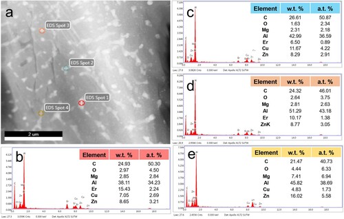
Samples were fabricated using 7075 aluminium alloy powders without and with 2 w.t.% Er elemental powder blended. Morphologies of the commercial spherical 7075 aluminium alloy powders (supplied by Beijing Crigoo Materials Technology Co., Ltd.) are shown in (a). The powders have a particle size distribution range between 20 and 63 μm. The chemical composition of 7075 aluminium alloy powders is provided in . Er elemental powders were supplied in random shape (shown in (b)) and sieved to remove powders with a size over 75 μm. 7075 powders with Er addition were prepared with a ball milling machine in a corundum jar. ZrO2 milling balls, which consisted of 20% of milling balls with a diameter of 15 mm, 50% with a diameter of 12 mm, and 30% with a diameter of 5 mm, were employed. The weight ratio of ball-to-powder was set as 1:1. A rotation speed of 300 rpm for 8 h was employed. (c) and d depict the morphology of the mixed powders. The aluminium powders remain spherical while irregular particles of different sizes ranging from about 1 to 20 μm distribute around them as satellites. These irregular particles are identified as Er, according to the EDS results in (e). In the corresponding EDS spectra of spots 2–4, Er accounts for the main element. The existence of Al and other alloying elements can be due to the resolution limit of EDS. No reaction between Al and Er is expected to occur during the ball milling process, indicating that small elemental Er particles of about 1 μm are obtained.
Figure 1. SEM and EDS images of the powders: (a) 7075 powders, (b) Er powders, (c) mixed powders, (d) high magnification of mixed powders, (e–h) corresponding EDS spectra of spot 1–4 marked in c and d.
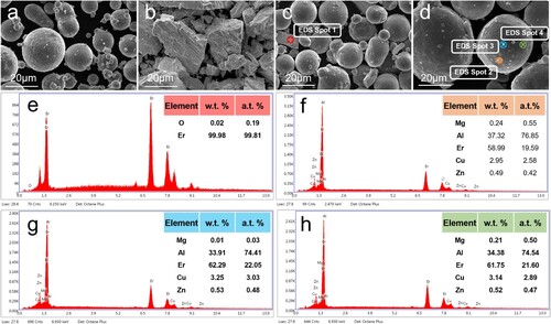
Table 1. Chemical composition of 7075 aluminium powders in w.t. %.
2.2. SLM process
The fabrication process was conducted using an SLM 125 HL machine (SLM Solutions Group AG). The machine was customised to be equipped with a fibre laser (1064 nm), with a maximum laser power of 400 W and a focus diameter of 80 μm. To prevent oxidation and interstitial element contaminations, the sample fabrication was carried out in an argon atmosphere with less than 0.1% oxygen. A 150°C preheat procedure of the substrate was employed before fabrication. The scanning strategy recommended by the machine program is illustrated in . Samples with a 5 × 5 × 6 mm dimension were fabricated with parameters listed in . Four samples for each group were fabricated. The volumetric energy density (E) in can be calculated by Equation (1).
(1)
(1) where P is the laser power (W), v is the scanning speed (mm/s), h is the hatching space (μm) and t is the layer thickness (μm).
Figure 2. (a) Schematic illustration of the sample with the coordinate system showing the orientations. A scanning strategy with a layer-by-layer 67° rotation and the characterised planes are displayed. (b) The position and dimension of the specimen used for Micro-CT characterisation.
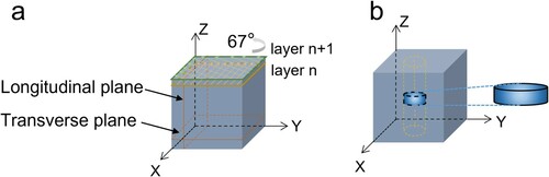
Table 2. The processing parameters of the respective samples.
2.3. Defects analysis
After detaching the samples from the substrate by wire-cut electrical discharge machining (EDM), density was subsequently measured based on Archimedes’ principle. To analyse the defects, two cross-sectional areas, illustrated in (a), were ground and polished. An optical microscope (OM, Olympus BX53M) was employed to characterise both planes. Five selected areas in each plane were captured and analysed. The crack density and porosity measurements in the present study were conducted based on these OM images. The crack density is defined as the crack length per unit area by Equation (2).
(2)
(2)
Similarly, the definition of porosity is the area percentage of pores, as shown in Equation (3).
(3)
(3)
A micro-computerised tomography (CT) scanner (Brucker Skyscan 2211) scanned the parts to further reveal the distribution of pores. A limited volume of Φ 0.7 × 0.2 mm column, illustrated in (b), was scanned due to the resolution consideration. X-ray scanning was performed at a voltage of 50 kV and a current of 390 mA to collect 2D slice image data. NRecon software was subsequently employed to reconstruct the 3D models through the 2D slice image data.
2.4. Phase identification and microstructure characteristics
After being etched with Keller’s reagent, microstructural characterisation was performed using OM and a scanning electron microscope (SEM, Quanta 250). The phase constitution of powders and bulk specimens was examined by X-ray diffraction (XRD, Bruker D8 Advance), using Cu Kα radiation at 40 kV and 40 mA, respectively. Transmission electron microscopy (TEM), scanning transmission electron microscopy (STEM), high-resolution TEM (HRTEM) and EDS spectroscopy were carried out at 200 kV using a Tecnai G2 Spirit TWIN equipped with an EDS system to identify the sub-micrometer and nanometer compounds.
3. Results
3.1. Defects analysis
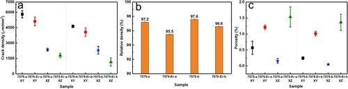
The crack density of the samples was measured, according to Equation (2) in Section 2.3. (a) compares the crack density of samples with different treatments. It shows that the crack density on the transversal XY plane of the samples fabricated with as-received 7075 powders is as much as 5806 and 4632 μm/mm2 at the volumetric energy density of 69 and 90 J/mm3, respectively. After Er modification, the crack density is reduced to 5117 and 4073 μm/mm2, respectively. In contrast, the crack density on the longitudinal XZ plane along the building direction is much lower than that on the XY plane. It was measured as 2354 and 2305 μm/mm2 on the XZ plane in Sample 7075-a and 7075-b, respectively. Similarly, it shows a decreasing trend when Er is added. There are 1792 and 1157 μm/mm2 crack density values in Sample 7075-Er-a and 7075-Er-b, respectively. Unfortunately, the relative density of the Er-modified parts decreases to a lower level compared with that of the 7075 counterparts (shown in (b)). For higher volumetric energy density, the relative density decreases from 97.6% to 96.6%. The seemingly anomalous phenomenon can be well explained after the porosity is measured. Based on Equation (3), the porosity measured is plotted in (c). The pores displayed on the XY plane show a higher percentage than those on the XZ plane. Increasing volumetric energy density decreases the porosity slightly as well. With Er addition, the porosity dramatically increases, especially that on the plane along building direction. It witnesses an increase from 0.05% to 1.37% on the XZ plane at the volumetric energy density of 90 J/mm3, which reduces the relative density of the sample.
Figure 3. Crack density at transverse XY and longitudinal XZ plane (a), Relative density (b), and Porosity at transverse XY and longitudinal XZ plane (c) of samples with different treatments.
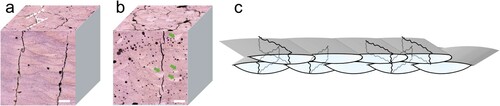
The distribution of cracks and pores on each surface of Sample 7075-b and 7075-Er-b was depicted after slight etching, as illustrated in . Melting boundaries with ellipsoid shapes on the XY plane were generated due to the rotation during the track-by-track building process. Reticular distribution of cracks can be easily observed. The majority of the cracks on the XY plane are along the centre area of the molten pools, where cellular or dendritic grains grow with long channels of interdendritic liquid trapped between solidified regions. At a later stage of solidification, hot tearing cracks may form and propagate along the length of the columnar grain due to volumetric solidification shrinkage and thermal contraction. Other cracks propagate, crossing the molten pools perpendicularly or along the boundaries of the molten pool, resulting in a network distribution. A hypothesis is proposed that cracks in neighbouring layers propagate along the building direction and join together because of the layer-bylayer 67° rotation build-up. An approximate 70° angle between neighbouring cracks is marked by the dashed lines in (a). Massive molten pool boundaries with arc shapes were formed on the XZ plane owing to the layer-by-layer manufacturing process. The linear cracks along the building direction are witnessed. Undoubtedly the cracks on the plane along the building direction mainly extend along the centre of the molten pools. There is little shift of the cracks because of the layer-by-layer 67° rotation. An illustration of crack distribution from a 3D view is displayed in (c). Cracks in neighbouring layers may propagate along the building direction and join each other, resulting in the reticular distribution of cracks.
Figure 4. Optical isometric macrographs of (a) Sample 7075-b, and (b) Sample 7075-Er-b. (c) The schematic illustration of the crack distribution corresponding to the layer-by-layer 67° rotation scanning strategies. Scale bar in a and b is 100 μm. An approximate 70° angle between neighbouring cracks is marked by the dashed line in a. Green arrows indicate the bright molten pools with fewer defects.
After being further etched, cracks between the grains are revealed. In contrast to the plain 7075 alloy, the Er addition reduces these cracks, as displayed in Figure S1(a,b). Some molten pools with higher contrast emerge in (b), marked by the green arrows. It is interesting that fewer defects appear in these molten pools, which have a higher aspect ratio (Figure S1(c)). The molten pools with such features are assumed to be subjected to a higher laser energy. A further study is thus worthily planned.
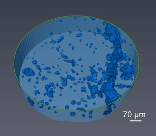
Meanwhile, the porosity increased significantly with Er addition on each surface (), consistent with the data in (c). Both large irregular pores and spherical pores with size in a wide range emerge in Sample 7075-Er-b. As shown in Figure S1(b,c), some particles are distributed at the bottom of the molten pool or between the laser tracks. Some pores are spread around these particles. Micro-CT was performed to reveal the spatial distribution of cracks and pores. As seen in (c), the defects of Sample 7075-Er-b are reduced at elevated laser energy density. Therefore, micro-CT of Sample 7075-Er-b was performed, as shown in . It shows that there are large irregular pores, indicating a high percentage of lack-of-fusion pores after Er modification. This accounts for the insufficient relative density. Planar-like cracks can be found, verifying the crack propagation hypothesis, shown in (c). Volumetric porosity and crack density are calculated thereby. A total vacancy of crack and pores is as high as 2.99%, which agrees with the relative density.
Figure 5. Reconstructed micro-CT image of Sample 7075-Er-b. The dimension is Φ 0.7 × 0.2 mm.
3.2. Phase identification
shows the SEM images of the XY plane of Samples 7075-b and 7075-Er-b. A reduced crack density and an increased porosity with Er addition show consistency with and . Details of defects and microstructure are shown. After being etched, the cracks and pores are enlarged and more clearly displayed. Apart from the wide cracks along the centre of the molten pool, some thinner micro-cracks also appear. Micro-cracks propagate along with the molten pools in adjacent layers in Sample 7075-b, as depicted in (a). It is an indication that coarse columnar grains grow along longitudinal building directions due to epitaxial growth. Cracks propagate along the vulnerable regions between the columnar grains. In Sample 7075-Er-b, micro-cracks appear in shorter in length, distributing mainly around the molten pool boundaries (MPB). Different orientations of grains are marked by the dashed lines in (d), signifying that epitaxial growth is distracted. In comparison with the microstructure in (c), it seems that the columnar grains grow further into the molten pool. However, finer inter-granular space is recognised, allowing fewer micro-cracks to initiate and propagate along with them. A similar reduction of micro-cracks on the XZ plane in Er-modified sample is also observable in (a,b), consistent with the initial analysis.
Figure 6. SEM images of the XZ plane in (a, c) Sample 7075-b and (b, d) Sample 7075-Er-b. (e) Magnified SEM image showing white particles in the XZ plane.
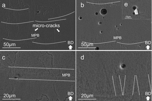
Figure 7. The SEM images of the XY plane in (a) Sample 7075-b, (b) Sample 7075-Er-b. (c) Corresponding EDS results of the white particles in the XY plane.
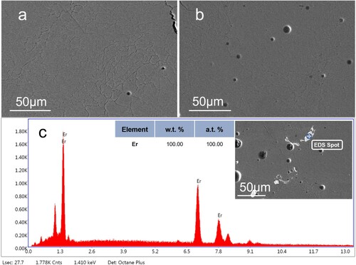
White particles, corresponding to the particles circled in Figure S1, can be observed in both XY and XZ planes, as shown in (e) and (c), respectively. These phases can be identified with EDS spectra. The EDS results in (c) show that Er element accounts for the only metallic element. Therefore, these particles can be identified as unmelted Er elements. Some pores spread around the unmelted Er particles, indicating gas absorption on them.
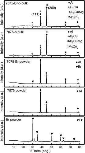
XRD was carried out to analyse the phases of the alloys. shows the XRD results of the materials used in the present study. Unoubted, only Er peaks can be detected in the elemental powder. In the mixed powders, Er peak remains. However, even though unmelted Er particles exist in the printed bulks, it is difficult to find the corresponding peaks. There are no other Er-containing compounds as well. Therefore, detailed information is of necessity to further characterise the evolution of Er. Interestingly, the main orientation of aluminium is to convert from (111) in powders to (200) in bulks. It is little relevant to the present study but can be explored in future study.
Figure 8. XRD spectra of powder and bulk materials.
(HR)TEM observations were carried out on a Tecnai G2 Spirit TWIN transmission electron microscope. shows that particles with different scales distribute in the matrix of the alloys. EDS spectra of spot 1–3 obtained in the STEM mode show that the particles with a size of around 200 nm contain Er, Al, Cu, and Zn, etc. The high carbon contents can be due to the residual ethanol with which the TEM specimen was kept. In the EDS spectrum of spot 4, only alloying elements, such as Al, Cu, Mg and Zn, appear, signifying the existence of sub-micrometer secondary phases of the 7075 alloy. It is concluded that Er-containing sub-micrometer particles distribute among the secondary phases of the 7075 alloy. It is worthy to note that although the laser energy is insufficient to fully melting the large Er powders, small ones do melt and react to form intermetallics.
Figure 9. The EDS results of Sample 7075-Er-b obtained in the STEM mode. The majority of particles with a size of around 200 nm contain Er.
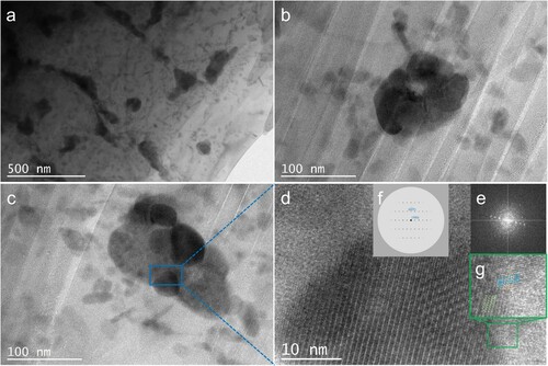
(a) shows the same kind of particles as those in . Magnification images of these particles in (b,c) show that smaller Er-containing particles with nano-scale aggregate form a sub-micrometer one. (d) is the HRTEM image, taken along a [0 1 2] zone axis, for the particle marked in (c). The inset (e) shows the corresponding FFT image of (d), while the one in (f) is the simulated FFT image of Al3Er along a [0 1 2] zone axis. The consistency of the simulated and the experimental FFT images identifies the Al3Er compound. Although other elements are detected in the EDS spectra, it is believed to be due to the resolution limit. It is obvious that the precipitate with a diameter of about 30 nm is coherent with the matrix, as marked by the dashes in the inset (g). Therefore, Al3Er is assumed to be able to act as the potent nuclear agent of aluminium grains. In the SEM images, it has been shown that finer columnar grains form. Therefore, it can be induced that Al3Er can refine the grains although further research is required to obtain fully equiaxed grains.
Figure 10. TEM microstructural characterisation. (a) Low magnification TEM images taken from 7075-Er-b show the same type of particles as those in , (b–c) Er containing particles of high magnification, (d) the corresponding HRTEM of the particle marked in c. The insets e and f are experimental and stimulated FFT images, respectively. The enlarged inset g shows the coherency between the particle and the matrix.
4. Discussion
The present study aims to reduce the defects of cracks with Er modification. Er was used to refine α-Al grains in Al(-Si)-Mg alloys and improve mechanical properties (Wen et al. Citation2009; Kuo et al. Citation2020). Therefore, it is important to explore the influence of Er on defects of SLM-fabricated aluminium alloys. However, it is found that porosity increased due to the Er addition, which must be explained and further avoided. The pores can be divided into two categories according to their shapes and sizes. The first type with irregular morphology and larger sizes can be referred to as ‘lack-of-fusion’ pores (Maskery et al. Citation2016). As the melting point of Er is 1529°C (Okamoto Citation2011), the laser energy density and the beam-material interaction time of the study are not sufficient to melt all the Er particles. If the Er particles are at the boundaries of the laser track, the lack-of-fusion pores may emerge between the tracks of the scanning laser beams. Spherical pores are referred to as metallurgical pores, which are assumed to be formed because of entrapped gases in the molten pool (Weingarten et al. Citation2015; Yu et al. Citation2019). The gas pores possibly originate from the gas or moisture absorbed on the powder or from inside the environmental chamber. Keyhole porosity is less considered because few pores spread at the bottom of the molten pools with a low aspect ratio.
In wide and shallow molten pools, the fluid is dominated by an outward Marangoni flow, which tends to sweep the bubbles towards the solidification front, resulting in a high porosity (Le and Yu-Lung Citation2019). By the Marangoni convection, most pores are driven outwards and downwards along the solidification front. As the temperature and velocity decrease at a later stage of solidification, pores rise because of the buoyancy. Poor velocity leaves high porosity in the molten pools, with some pores coalescing to form larger pores (Martin et al. Citation2019; Zhao et al. Citation2020; Leung et al. Citation2018). When survival Er particles exist, they tend to spread at the bottom of the molten pool due to the high density. Increased viscosity of the molten pool is predictable, making it difficult for the pores to escape.
illustrates how Er-modified 7075 powders are different from the as-received 7075 powders. When 7075 powders with spherical morphology were subjected to laser beam, a shallow and wide molten pool was formed. The viscosity of the liquid is low, and the pores in the molten pools find it easy to escape. However, in the solidifying process, the cooling rate in the SLM process is as high as ∼106 K/s (Tan et al. Citation2020), large coarse columnar grains along the temperature gradient are consequently formed. The cavity forms because of poor interdendritic fluidity. This initial cavity would propagate through interdendritic colonies and layers under the thermal stress caused by the cycled heat input. Hence, cracks oriented parallel to the columnar grains can be witnessed.
Figure 11. Schematic illustration of how Er-modified 7075 powders are different from the as-received 7075 powders. (a) When 7075 powders are subjected to laser beam, wide and shallow molten pools are formed, resulting in the outward Marangoni flow. Coarse columnar grains form due to epitaxial growth and temperature gradient in the molten pool. Long and wide cracks, therefore, initiate and propagate along the interdendritic colonies. (b) Irregular Er powders distribute around spherical 7075 powders. When exposed to laser beam, outward Marangoni flow, which tends to sweep the bubbles towards the solidification front, together with the unmelted Er particles, leads to increased gas porosity. When the Er particles reside in between the molten pools, lack-of-fusion pores may form. Because of the formation of Al3Er intermetallic, the nucleation of α-Al is facilitated, with finer grains in the molten pools. Cracks are thus reduced.
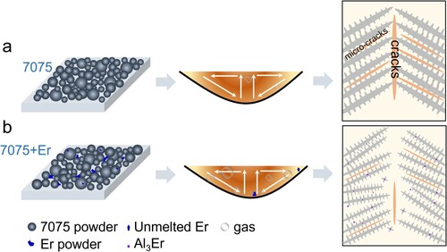
When irregular Er particles are mixed with 7075 powders, the laser beam would not fully melt Er particles due to their high melting temperature. However, it is believed that more laser energy is absorbed because specific surface area increases. Some molten pools are thus deeper with a higher aspect ratio. In the molten pools, unmelted Er particles are represented by blue particles. Compared with the raw mixed powders, the final Er particles decrease in size after partial melting in aluminium melts. When the temperature decreases, the Er and Al atoms form Al3Er compounds with nano-scale and sub-micrometer scales. Al3Er, with an L12 structure, exhibits less than 4.1% lattice mismatch with the primary face-centred-cubic aluminium phase, and provides an ideal low-energy heterogeneous nucleation site (van Dalen et al. Citation2009). The numerous particles can also be expelled at the grain boundary, restricting the growth of grains (Huang et al. Citation2021). Both effects facilitate the finer grains. However, as the impact of Al3Er is inferior to Al3Sc (van Dalen et al. Citation2009), columnar grains cannot be fully avoided. Therefore, cracks can still be observed despite a crack reduction.
5. Conclusion
In the present work, Er-modified 7075 aluminium alloys powders prepared with ball milling effectively reduced crack. However, the porosity was increased from 0.05% to 1.37% on the XZ plane with the volumetric energy density of 90 J/mm3. The phenomenon is well interpreted by the evolution of Er. Due to the insufficient energy density, Er with a high melting point was not completely melted. The survival Er particles deteriorate the fluidity of the molten pool and lead to higher porosity. The product of the melting Er and Al is identified to be Al3Er intermetallic, which help to refine the grains and reduce the cracks. The work sheds some new light in the investigation of 7075 aluminium alloys fabricated with SLM.
Supplemental Material
Download TIFF Image (6.7 MB)Disclosure statement
No potential conflict of interest was reported by the author(s).
Additional information
Funding
Notes on contributors
Xuhui Zhang
Xuhui Zhang is currently a postgraduate student from the Centre for Advanced Laser Manufacturing, Shandong University of Technology. Her research interest is selective laser melting of aluminium alloys.
Zhen Xiao
Zhen Xiao is a lecturer at the Centre for Advanced Laser Manufacturing, Shandong University of Technology. He is mainly working on additive manufacturing of metals.
Wenhui Yu
Wenhui Yu is a lecturer at the Centre for Advanced Laser Manufacturing, Shandong University of Technology. She is mainly working on additive manufacturing of metals.
Chee Kai Chua
Chee Kai Chua is the Head of Pillar for Engineering Product Development (EPD) and Cheng Tsang Man Chair Professor at SUTD. His research area is in 3D Printing & Rapid Prototyping or Additive Manufacturing.
Lihua Zhu
Linhua Zhu is a lecturer at the Centre for Advanced Laser Manufacturing, Shandong University of Technology. He is mainly working on laser materials processing.
Zongshen Wang
Zongshen Wang is Associate Professor at the Centre for Advanced Laser Manufacturing, Shandong University of Technology. He is mainly working on laser materials processing and surface engineering.
Peng Xue
Peng Xue is an engineer in Shengli Oilfield Highland Petroleum Equipment Co., Ltd.
Shuai Tan
Shuai Tan is an engineer in Shengli Oilfield Highland Petroleum Equipment Co., Ltd.
Yongling Wu
Yongling Wu is a professor at the Centre for Advanced Laser Manufacturing, Shandong University of Technology. Her research area is in surface engineering and characterisation of materials.
Hongyu Zheng
Hongyu Zheng is the dean of the School of Mechanical Engineering, Shandong University of Technology. His research area is in laser manufacturing.
Related Research Data
References
- Cai, Xingfang, Andrew Alexander Malcolm, Brian Stephen Wong, and Zheng Fan. 2015. “Measurement and Characterization of Porosity in Aluminium Selective Laser Melting Parts Using X-Ray CT.” Virtual and Physical Prototyping 10 (4): 195–206. doi:https://doi.org/10.1080/17452759.2015.1112412.
- Chen, Shengyang, Tae-Sik Jang, Houwen Matthew Pan, Hyun-Do Jung, Ming Wei Sia, Shuying Xie, Yao Hang, Mark Chong Seow Khoon, Dongan Wang, and Juha Song. 2020. “3D Freeform Printing of Nanocomposite Hydrogels Through in Situ Precipitation in Reactive Viscous Fluid.” International Journal of Bioprinting 6 (2): 21. doi:https://doi.org/10.18063/ijb.v6i2.258.
- Croteau, Joseph R., Seth Griffiths, Marta D. Rossell, Christian Leinenbach, Christoph Kenel, Vincent Jansen, David N. Seidman, David C. Dunand, and Nhon Q. Vo. 2018. “Microstructure and Mechanical Properties of Al-Mg-Zr Alloys Processed by Selective Laser Melting.” Acta Materialia 153: 35–44. doi:https://doi.org/10.1016/j.actamat.2018.04.053.
- DebRoy, T., H. L. Wei, J. S. Zuback, T. Mukherjee, J. W. Elmer, J. O. Milewski, A. M. Beese, A. Wilson-Heid, A. De, and W. Zhang. 2018. “Additive Manufacturing of Metallic Components – Process, Structure and Properties.” Progress in Materials Science 924: 112–224. doi:https://doi.org/10.1016/j.pmatsci.2017.10.001.
- Ding, Xueping, and Linzhi Wang. 2017. “Heat Transfer and Fluid Flow of Molten Pool During Selective Laser Melting of AlSi10Mg Powder: Simulation and Experiment.” Journal of Manufacturing Processes 26: 280–289. doi:https://doi.org/10.1016/j.jmapro.2017.02.009.
- Greco, Sebastian, Kevin Gutzeit, Hendrik Hotz, Benjamin Kirsch, and Jan C. Aurich. 2020. “Selective Laser Melting (SLM) of AISI 316L – Impact of Laser Power, Layer Thickness, and Hatch Spacing on Roughness, Density, and Microhardness at Constant Input Energy Density.” The International Journal of Advanced Manufacturing Technology 108 (5–6): 1551–1562. doi:https://doi.org/10.1007/s00170-020-05510-8.
- Heinz, A., A. Haszler, C. Keidel, S. Moldenhauer, R. Benedictus, and W. S. Miller. 2000. “Recent Development in Aluminium Alloys for Aerospace Applications.” Materials Science and Engineering: A 280 (1): 102–107. doi:https://doi.org/10.1016/S0921-5093(99)00674-7.
- Hu, Xiaowu, Fugang Jiang, Fanrong Ai, and Hong Yan. 2012. “Effects of Rare Earth Er Additions on Microstructure Development and Mechanical Properties of Die-Cast ADC12 Aluminum Alloy.” Journal of Alloys and Compounds 538: 21–27. doi:https://doi.org/10.1016/j.jallcom.2012.05.089.
- Hu, Zhiheng, Xiaojia Nie, Yang Qi, Hu Zhang, and Haihong Zhu. 2021. “Cracking Criterion for High Strength Al–Cu Alloys Fabricated by Selective Laser Melting.” Additive Manufacturing 37: 101709. doi:https://doi.org/10.1016/j.addma.2020.101709.
- Huang, Sheng, R. Lakshmi Narayan, Kuan Tan Joel Heang, Swee Leong Sing, and Wai Yee Yeong. 2021. “Resolving the Porosity-Unmelted Inclusion Dilemma During in-Situ Alloying of Ti34Nb via Laser Powder Bed Fusion.” Acta Materialia 204: 116522. doi:https://doi.org/10.1016/j.actamat.2020.116522.
- Jia, Qingbo, Paul Rometsch, Sheng Cao, Kai Zhang, Aijun Huang, and Xinhua Wu. 2018. “Characterisation of AlScZr and AlErZr Alloys Processed by Rapid Laser Melting.” Scripta Materialia 151: 42–46. doi:https://doi.org/10.1016/j.scriptamat.2018.03.035.
- Kaufmann, N., M. Imran, T. M. Wischeropp, C. Emmelmann, S. Siddique, and F. Walther. 2016. “Influence of Process Parameters on the Quality of Aluminium Alloy EN AW 7075 Using Selective Laser Melting (SLM).” Physics Procedia 83: 918–926. doi:https://doi.org/10.1016/j.phpro.2016.08.096.
- Kuo, C. N., C. K. Chua, P. C. Peng, Y. W. Chen, S. L. Sing, S. Huang, and Y. L. Su. 2020. “Microstructure Evolution and Mechanical Property Response via 3D Printing Parameter Development of Al–Sc Alloy.” Virtual and Physical Prototyping 15 (1): 120–129. doi:https://doi.org/10.1080/17452759.2019.1698967.
- Le, Trong-Nhan, and Lo Yu-Lung. 2019. “Effects of Sulfur Concentration and Marangoni Convection on Melt-Pool Formation in Transition Mode of Selective Laser Melting Process.” Materials & Design 179: 107866. doi:https://doi.org/10.1016/j.matdes.2019.107866.
- Lei, Zhenglong, Jiang Bi, Yanbin Chen, Xi Chen, Xikun Qin, and Ze Tian. 2019. “Effect of Energy Density on Formability, Microstructure and Micro-Hardness of Selective Laser Melted Sc- and Zr- Modified 7075 Aluminum Alloy.” Powder Technology 356: 594–606. doi:https://doi.org/10.1016/j.powtec.2019.08.082.
- Leung, Chu Lun Alex, Sebastian Marussi, Robert C. Atwood, Michael Towrie, Philip J. Withers, and Peter D. Lee. 2018. “In Situ X-Ray Imaging of Defect and Molten Pool Dynamics in Laser Additive Manufacturing.” Nature Communications 9 (1): 1355. doi:https://doi.org/10.1038/s41467-018-03734-7.
- Li, Ruidi, Minbo Wang, Zhiming Li, Peng Cao, Tiechui Yuan, and Hongbin Zhu. 2020. “Developing a High-Strength Al-Mg-Si-Sc-Zr Alloy for Selective Laser Melting: Crack-Inhibiting and Multiple Strengthening Mechanisms.” Acta Materialia 193: 83–98. doi:https://doi.org/10.1016/j.actamat.2020.03.060.
- Liu, Peng, Jia-ying Hu, Huai-xue Li, Si-yu Sun, and Yuan-bin Zhang. 2020. “Effect of Heat Treatment on Microstructure, Hardness and Corrosion Resistance of 7075 Al Alloys Fabricated by SLM.” Journal of Manufacturing Processes 60: 578–585. doi:https://doi.org/10.1016/j.jmapro.2020.10.071.
- Liu, Xuefeng, Ang Li, Baoqiang Yin, Bo Yu, and Yang Yan. 2018. “Influence Law of Process Parameters on the Continuity and Dimensional Uniformity of 7075 Aluminum Alloy Single Tracks Manufactured by Selective Laser Melting.” In Advances in Materials Processing, edited by Yafang Han, 243–255. Singapore: Springer. Lecture Notes in Mechanical Engineering. doi:https://doi.org/10.1007/978-981-13-0107-0_23.
- Martin, Aiden A., Nicholas P. Calta, Saad A. Khairallah, Jenny Wang, Phillip J. Depond, Anthony Y. Fong, Vivek Thampy, et al. 2019. “Dynamics of Pore Formation During Laser Powder Bed Fusion Additive Manufacturing.” Nature Communications 10 (1): 1987. doi:https://doi.org/10.1038/s41467-019-10009-2.
- Martin, John H., Brennan D. Yahata, Jacob M. Hundley, Justin A. Mayer, Tobias A. Schaedler, and Tresa M. Pollock. 2017. “3D Printing of High-Strength Aluminium Alloys.” Nature 549 (7672): 365–369. doi:https://doi.org/10.1038/nature23894.
- Martinez, Rafael, Iain Todd, and Kamran Mumtaz. 2019. “In Situ Alloying of Elemental Al-Cu12 Feedstock Using Selective Laser Melting.” Virtual and Physical Prototyping 14 (3): 242–252. doi:https://doi.org/10.1080/17452759.2019.1584402.
- Maskery, I., N. T. Aboulkhair, M. R. Corfield, C. Tuck, A. T. Clare, R. K. Leach, R. D. Wildman, I. A. Ashcroft, and R. J. M. Hague. 2016. “Quantification and Characterisation of Porosity in Selectively Laser Melted Al–Si10–Mg Using X-Ray Computed Tomography.” Materials Characterization 111: 193–204. doi:https://doi.org/10.1016/j.matchar.2015.12.001.
- Murr, Lawrence E., Sara M. Gaytan, Diana A. Ramirez, Edwin Martinez, Jennifer Hernandez, Krista N. Amato, Patrick W. Shindo, Francisco R. Medina, and Ryan B. Wicker. 2012. “Metal Fabrication by Additive Manufacturing Using Laser and Electron Beam Melting Technologies.” Journal of Materials Science & Technology 28 (1): 1–14. doi:https://doi.org/10.1016/S1005-0302(12)60016-4.
- Nadammal, Naresh, Tatiana Mishurova, Tobias Fritsch, Itziar Serrano-Munoz, Arne Kromm, Christoph Haberland, Pedro Dolabella Portella, and Giovanni Bruno. 2021. “Critical Role of Scan Strategies on the Development of Microstructure, Texture, and Residual Stresses During Laser Powder Bed Fusion Additive Manufacturing.” Additive Manufacturing 38: 101792. doi:https://doi.org/10.1016/j.addma.2020.101792.
- Okamoto, H. 2011. “Al-Er (Aluminum-Erbium).” Journal of Phase Equilibria and Diffusion 32 (3): 261–262. doi:https://doi.org/10.1007/s11669-011-9877-y.
- Otani, Yuki, and Shinya Sasaki. 2020. “Effects of the Addition of Silicon to 7075 Aluminum Alloy on Microstructure, Mechanical Properties, and Selective Laser Melting Processability.” Materials Science and Engineering: A 777: 139079. doi:https://doi.org/10.1016/j.msea.2020.139079.
- Prashanth, K. G., S. Scudino, H. J. Klauss, K. B. Surreddi, L. Löber, Z. Wang, A. K. Chaubey, U. Kühn, and J. Eckert. 2014. “Microstructure and Mechanical Properties of Al–12Si Produced by Selective Laser Melting: Effect of Heat Treatment.” Materials Science and Engineering: A 590: 153–160. doi:https://doi.org/10.1016/j.msea.2013.10.023.
- Qbau, N., N. D. Nam, N. X. Ca, and N. T. Hien. 2020. “The Crack Healing Effect of Scandium in Aluminum Alloys During Laser Additive Manufacturing.” Journal of Manufacturing Processes 50: 241–246. doi:https://doi.org/10.1016/j.jmapro.2019.12.050.
- Qi, Ting, Haihong Zhu, Hu Zhang, Jie Yin, Linda Ke, and Xiaoyan Zeng. 2017. “Selective Laser Melting of Al7050 Powder: Melting Mode Transition and Comparison of the Characteristics Between the Keyhole and Conduction Mode.” Materials & Design 135: 257–266. doi:https://doi.org/10.1016/j.matdes.2017.09.014.
- Rodriguez-Salvador, Marisela, and Laura Ruiz-Cantu. 2019. “Revealing Emerging Science and Technology Research for Dentistry Applications of 3D Bioprinting.” International Journal of Bioprinting 5: 1. doi:https://doi.org/10.18063/ijb.v5i1.170.
- Salmi, Alessandro, and Eleonora Atzeni. 2020. “Residual Stress Analysis of Thin AlSi10Mg Parts Produced by Laser Powder Bed Fusion.” Virtual and Physical Prototyping 15 (1): 49–61. doi:https://doi.org/10.1080/17452759.2019.1650237.
- Shuai, Cijun, Wenjing Yang, Youwen Yang, Chengde Gao, Chongxian He, and Hao Pan. 2019. “A Continuous Net-Like Eutectic Structure Enhances the Corrosion Resistance of Mg Alloys.” International Journal of Bioprinting 5 (2): 49. doi:https://doi.org/10.18063/ijb.v5i2.207.
- Sing, S. L., S. Huang, G. D. Goh, G. L. Goh, C. F. Tey, J. H. K. Tan, and W. Y. Yeong. 2021a. “Emerging Metallic Systems for Additive Manufacturing: In-Situ Alloying and Multi-Metal Processing in Laser Powder Bed Fusion.” Progress in Materials Science 119: 100795. doi:https://doi.org/10.1016/j.pmatsci.2021.100795.
- Sing, S. L., C. N. Kuo, C. T. Shih, C. C. Ho, and C. K. Chua. 2021b. “Perspectives of Using Machine Learning in Laser Powder Bed Fusion for Metal Additive Manufacturing.” Virtual and Physical Prototyping 16 (3): 372–386. doi:https://doi.org/10.1080/17452759.2021.1944229.
- Stojanovic, Blaza, Bukvic Мilan, and Igor Epler. 2018. “Application of Aluminum and Aluminum Alloys in Engineering.” Applied Engineering Letters: Journal of Engineering and Applied Sciences 3 (2): 52–62. doi:https://doi.org/10.18485/aeletters.2018.3.2.2.
- Tan, Qiyang, Zhiqi Fan, Xiaoqin Tang, Yu Yin, Gan Li, Danni Huang, Jingqi Zhang, et al. 2021. “A Novel Strategy to Additively Manufacture 7075 Aluminium Alloy with Selective Laser Melting.” Materials Science and Engineering: A 821: 141638. doi:https://doi.org/10.1016/j.msea.2021.141638.
- Tan, Qiyang, Jingqi Zhang, Ning Mo, Zhiqi Fan, Yu Yin, Michael Bermingham, Yingang Liu, Han Huang, and Ming-Xing Zhang. 2020. “A Novel Method to 3D-Print Fine-Grained AlSi10Mg Alloy with Isotropic Properties via Inoculation with LaB6 Nanoparticles.” Additive Manufacturing 32: 101034. doi:https://doi.org/10.1016/j.addma.2019.101034.
- Trevisan, Francesco, Flaviana Calignano, Massimo Lorusso, Jukka Pakkanen, Alberta Aversa, Elisa Ambrosio, Mariangela Lombardi, Paolo Fino, and Diego Manfredi. 2017. “On the Selective Laser Melting (SLM) of the AlSi10Mg Alloy: Process, Microstructure, and Mechanical Properties.” Materials 10 (1): 76. doi:https://doi.org/10.3390/ma10010076.
- van Dalen, Marsha E., Richard A. Karnesky, Joseph R. Cabotaje, David C. Dunand, and David N. Seidman. 2009. “Erbium and Ytterbium Solubilities and Diffusivities in Aluminum as Determined by Nanoscale Characterization of Precipitates.” Acta Materialia 57 (14): 4081–4089. doi:https://doi.org/10.1016/j.actamat.2009.05.007.
- Wang, Jinlian, Jun Xu, and Feng Pan. 2018. “Effect of Annealing on Microstructure and Properties of Er Modified 5052 Alloy.” Results in Physics 10: 476–480. doi:https://doi.org/10.1016/j.rinp.2018.06.048.
- Weingarten, Christian, Damien Buchbinder, Norbert Pirch, Wilhelm Meiners, Konrad Wissenbach, and Reinhart Poprawe. 2015. “Formation and Reduction of Hydrogen Porosity During Selective Laser Melting of AlSi10Mg.” Journal of Materials Processing Technology 221: 112–120. doi:https://doi.org/10.1016/j.jmatprotec.2015.02.013.
- Wen, S. P., K. Y. Gao, Y. Li, H. Huang, and Z. R. Nie. 2011. “Synergetic Effect of Er and Zr on the Precipitation Hardening of Al–Er–Zr Alloy.” Scripta Materialia 65 (7): 592–595. doi:https://doi.org/10.1016/j.scriptamat.2011.06.033.
- Wen, S. P., Z. B. Xing, H. Huang, B. L. Li, W. Wang, and Z. R. Nie. 2009. “The Effect of Erbium on the Microstructure and Mechanical Properties of Al–Mg–Mn–Zr Alloy.” Materials Science and Engineering: A 516 (1–2): 42–49. doi:https://doi.org/10.1016/j.msea.2009.02.045.
- Wenhui, Yu, Swee Leong Sing, Chee Kai Chua, and Xuelei Tian. 2019. “Influence of Re-Melting on Surface Roughness and Porosity of AlSi10Mg Parts Fabricated by Selective Laser Melting.” Journal of Alloys and Compounds 792: 574–581. doi:https://doi.org/10.1016/j.jallcom.2019.04.017.
- Wu, Hong, Yaojia Ren, Junye Ren, Anhui Cai, Min Song, Yong Liu, Xiaolan Wu, et al. 2020. “Effect of Melting Modes on Microstructure and Tribological Properties of Selective Laser Melted AlSi10Mg Alloy.” Virtual and Physical Prototyping 15 (Suppl. 1): 570–582. doi:https://doi.org/10.1080/17452759.2020.1811932.
- Xing, Pengfei, Bo Gao, Yanxin Zhuang, Kaihua Liu, and Ganfeng Tu. 2010. “Effect of Erbium on Properties and Microstructure of Al-Si Eutectic Alloy.” Journal of Rare Earths 28 (6): 927–930. doi:https://doi.org/10.1016/S1002-0721(09)60222-2.
- Yang, Youwen, Guoyong Wang, Huixin Liang, Chengde Gao, Shuping Peng, Lida Shen, and Cijun Shuai. 2019. “Additive Manufacturing of Bone Scaffolds.” International Journal of Bioprinting 5: 1. doi:https://doi.org/10.18063/ijb.v5i1.148.
- Yu, W. H., S. L. Sing, C. K. Chua, C. N. Kuo, and X. L. Tian. 2019. “Particle-Reinforced Metal Matrix Nanocomposites Fabricated by Selective Laser Melting: A State of the Art Review.” Progress in Materials Science 104: 330–379. doi:https://doi.org/10.1016/j.pmatsci.2019.04.006.
- Zhang, Han, Dongdong Gu, Donghua Dai, Chenglong Ma, Yuxin Li, Ruolin Peng, Shuhui Li, Gang Liu, and Biqi Yang. 2020. “Influence of Scanning Strategy and Parameter on Microstructural Feature, Residual Stress and Performance of Sc and Zr Modified Al–Mg Alloy Produced by Selective Laser Melting.” Materials Science and Engineering: A 788: 139593. doi:https://doi.org/10.1016/j.msea.2020.139593.
- Zhang, Jinliang, Bo Song, Qingsong Wei, Dave Bourell, and Yusheng Shi. 2019. “A Review of Selective Laser Melting of Aluminum Alloys: Processing, Microstructure, Property and Developing Trends.” Journal of Materials Science & Technology 35 (2): 270–284. doi:https://doi.org/10.1016/j.jmst.2018.09.004.
- Zhao, Yufan, Kenta Aoyagi, Kenta Yamanaka, and Akihiko Chiba. 2020. “Role of Operating and Environmental Conditions in Determining Molten Pool Dynamics During Electron Beam Melting and Selective Laser Melting.” Additive Manufacturing 36: 101559. doi:https://doi.org/10.1016/j.addma.2020.101559.
- Zolfagharian, Ali, Martin Denk, Abbas Z. Kouzani, Bodaghi Bodaghi, Saeid Nahavandi, and Akif Kaynak. 2020. “Effects of Topology Optimization in Multimaterial 3D Bioprinting of Soft Actuators.” International Journal of Bioprinting 6: 2. doi:https://doi.org/10.18063/ijb.v6i2.260.