
ABSTRACT
Bimetallic structures of Ti6Al4V-W7Ni3Fe were fabricated via directed energy deposition (DED)-based additive manufacturing (AM). Our research demonstrates the ability of DED-based AM to control Ti6Al4V-W7Ni3Fe bimetallic structures with tailorable mechanical and thermal performance. The thermal conductivity of the bimetallic structures was three times higher than Ti6Al4V at 300°C. Uniaxial compression along the transverse direction showed a failure strain of 63% compared to pure Ti6Al4V, while the longitudinal direction showed a failure strain of only 37% of Ti6Al4V. Variable hardness was observed throughout the sample due to diffusion of elements and intermetallic phase formations. Scanning electron microscopy revealed that the interfaces in the as-printed samples were crack-free with elemental gradients.
1. Introduction
Multi-material structures with varying functionality can offer a unique solution to engineering problems compared to single-material structures. One common type of multi-material structure is metal-ceramic composites, such as SS316L + TiB2, which have been shown to improve the mechanical properties of the matrix material (Ang, Sing, and Lim Citation2022). Another type of multi-material structure is bimetallic layered structures, composites with unique and tailorable properties for various applications such as ballistics and aerospace. One type of alloy commonly used in these applications is tungsten heavy alloys (WHAs), a material composed of 90–97 wt% W with lower melting point elements such as Cu, Fe, Ni, or Co (Bose et al. Citation2018). In physical terms, these alloys consist of unmelted W particles held together by a lighter and ductile element matrix (Şahin Citation2014). Performance-wise, the combination of the body-centered cubic (BCC) tungsten phase and the face-centered cubic (FCC) metallic matrix gives the WHAs outstanding properties such as high density (16–18 g/cm3), high strength (1000–1700 MPa), high ductility (10–30%), high thermal conductivity, and good corrosion resistance (Srikanth and Upadhyaya Citation1984). Due to these properties, WHAs have been widely applied in nuclear plants for radiation shields, defense, vibration dampers, and various aerospace applications (Cai et al. Citation1995; Park et al. Citation2001; Ryu and Hong Citation2003; Sunwoo et al. Citation2006; Liu et al. Citation2008). Liquid-phase sintering (LPS) is the most common method to process the WHAs. The WHA processed via LPS showed higher ductility than that processed by solid-state sintering (SSS) (Gurwell et al. Citation1984). However, there are still some disadvantages of the WHAs processed via LPS. The main disadvantage is the weak particle-particle interaction between each tungsten particle which could be the source of crack initiation even in well-sintered WHA materials (Gurwell et al. Citation1984). Other disadvantages of using LPS to process WHAs are the lack of flexibility and the cost. It has been reported that using LPS to process WHAs requires a long sintering time at high temperatures (typically ∼ 60 min at ∼ 1500°C) to keep melting the feedstock materials to promote diffusion and densification. The sintering time can even be longer for larger components (German, Suri, and Park Citation2009). Although some advanced sintering techniques, such as spark plasma sintering (SPS) and microwave sintering (MS), have shown time-related cost reduction in processing the WHAs, the density of the processed WHAs by SPS and MS is lower than the one processed via the LPS method. Furthermore, preparing samples with homogeneous microstructure for large parts with complex geometry is challenging using these sintering techniques (Zhou et al. Citation2021). Due to these drawbacks, researchers have been gravitating toward using various additive manufacturing (AM) techniques to create dense WHA parts in a time-efficient manner (Li et al. Citation2020).
Directed energy deposition (DED) is an AM method popular for large structures and parts with compositional variations. The laser-based DED uses a laser as energy input to melt the powder feedstocks on a metallic substrate. The raster scan motion allows the previous molten region to experience rapid solidification. The final structure processed by the DED method could have a near-net shape from the digital design and is achieved by repeating the laser raster scan and layer-by-layer processing. Moreover, many DED systems have multiple powder feeders and real-time control over the processing parameters such as laser power, laser scan speed, and powder feed rate, enabling multi-material fabrication in one operation. The coaxial powder deposition feature also improves the powder deposition efficiency. These advantages make DED one of the optimal ways for manufacturing WHAs, particularly with W7Ni3Fe (Wei et al. Citation2021; Zhou et al. Citation2021; Ye et al. Citation2022). Furthermore, these advantages allow for the capability to process multi-material structures such as Inconel 718/ GRCop 84 copper alloy, Ti6Al4V/SS 410, Ti6Al4V/Al12Si, Ni-Ti, SS 316L/Al12Si, Inconel 718/Ti6Al4V, and Inconel 718-W7Ni3Fe (Onuike and Bandyopadhyay Citation2018, Citation2019, Citation2020; Zhang and Bandyopadhyay Citation2019, Citation2021; Afrouzian et al. Citation2022; Farzaneh et al. Citation2022; Groden et al. Citation2022). Due to the powder-based DED system, there are virtually endless bimetallic compositions in addition to those listed above that can be made with any custom alloy (Bandyopadhyay et al. Citation2022). The DED-processed multi-material structures showed enhanced mechanical properties compared to the single-material structures. Further, the DED’s processing time is lower than traditional sintering methods. The materials processed via the DED also showed homogenous microstructure across the parts.
One alloy that would greatly benefit from the thermal properties of WHAs is Ti6Al4V, which is one of the primary alloys used in aerospace applications due to its high strength-to-weight ratio, temperature resistance, corrosion resistance, and fatigue strength (Rodriguez et al. Citation2015; Denti et al. Citation2019; Liu and Shin Citation2019). Furthermore, the high weldability of Ti6Al4V makes it one of the optimal alloys to be used for metal AM (Liu and Shin Citation2019). In this work, a bimetallic system of Ti6Al4V and W7Ni3Fe was manufactured via DED and then underwent mechanical and thermal testing. The microstructure of the DED processed Ti6Al4V/W7Ni3Fe alloy bimetallic layered structure was characterised by the scanning electron microscope (SEM) and energy-dispersive spectroscopy (EDS). Mechanical and thermal properties such as microhardness, compressive strengths along longitudinal and transverse directions, and thermal diffusivity were measured on the DED-processed bimetallic layered structures. Each section was processed with different number of layers, to prove the consistency of DED method in processing materials at different scales.
2. Materials and methods
2.1. DED-based AM processing of Ti6Al4V-W7Ni3Fe bimetallic layered structures
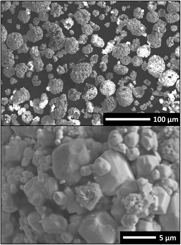
Spherical Ti6Al4V (ASTM B348-13, Grade 23, Oxygen < 0.10%, TEKNATM, Québec, Canada) and W7Ni3Fe alloy powders (TUNGSTEN PARTS WYOMING, WY, USA) were used as the feedstock materials. The W7Ni3Fe was an agglomerated powder consisting of spherical particles composed of fused W, Ni, and Fe particles. This morphology is shown in . A mechanical sieve shaker was utilised to sieve the powders for 15 min, and the powders with particle sizes ranging from 45 to 150 µm (−100/+325 mesh) for Ti6Al4V and 15–45 µm for W7Ni3Fe were collected for the best printing results. A DED system (FormAlloy, Spring Valley, CA) equipped with an optic fiber laser source (500 W maximum) was utilised to fabricate the Ti6Al4V/W7Ni3Fe alloy bimetallic layered structure. The DED system had two powder feeders, allowing the process to produce a structure with multiple materials. In this case, the W7Ni3Fe alloy powder was loaded into powder feeder 1, and the Ti6Al4V powder was loaded into powder feeder 2. Additionally, a Ti6Al4V metal substrate (Tiger Metals Group, Los Angeles, CA) with a thickness of 3 mm was used. In the preparation stage, the working chamber of the DED system was purged with Ar gas to reduce the O2 level below 20 ppm to prevent oxidation during the laser processing. The H2O level was controlled below 10 ppm. Prior to the processing of the bimetallic structures, process optimisation was done with each composition to identify optimum processing parameters with minimum defects while maintaining a layer height that is in line with the layer thickness based on the tool-path.
Figure 1. Morphology of the W7Ni3Fe Powder. (Top) Low magnification image of the agglomerated W7Ni3Fe powders. (Bottom) High magnification image of agglomerated W7Ni3Fe particles.
a illustrates the design of the DED processed Ti6Al4V-W7Ni3Fe bimetallic layered structure. The designed structure was composed of the W7Ni3Fe alloy section and Ti6Al4V section alternating. The in-fill laser scan orientation was set as 0 and 90 degrees (b). c demonstrates the schematic of the DED processing of the Ti6Al4V-W7Ni3Fe bimetallic layered structure. Both cylindrical shape (12.7 mm diameter) and square shape (13 mm × 13 mm, length × width) Ti6Al4V-W7Ni3Fe structures were fabricated. Additionally, the Ti6Al4V-W7Ni3Fe structures with a different number of layers in each section, such as 5 layers of W7Ni3Fe + 5 layers of Ti6Al4V alternating, 5 layers of W7Ni3Fe + 10 layers of Ti6Al4V alternating, 10 layers of W7Ni3Fe + 10 layers of Ti6Al4V alternating and 20 layers of W7Ni3Fe + 20 layers of Ti6Al4V alternating, were built to verify the performance of the processing parameters. shows the details of the optimised processing parameters to build each section of the Ti6Al4V-W7Ni3Fe bimetallic. Specifically, a W7Ni3Fe alloy section ((W7Ni3Fe) sec. 1) was initially deposited using a laser power of 270 W, a powder feed rate of 48.6 g/mm, and a laser scan speed of 600 mm/min. The layer thickness of the first (W7Ni3Fe) section was set as 0.22 mm. After the first W7Ni3Fe alloy section was done, a Ti6Al4V (sec. 1) section was deposited on top of the (W7Ni3Fe)1 section by utilising a 300 W laser power, 17.3 g/min powder feed rate, and 800 mm/min laser scan speed. The layer thickness of the Ti6Al4V section (sec. 1) was set as 0.35 mm. When the deposition of the Ti6Al4V section (sec. 1) was finished, another set of the W7Ni3Fe and Ti6Al4V sections, noted as W7Ni3Fe sec. 2 and Ti6Al4V sec. 2, were deposited on the top by using the corresponding processing parameters. The hatch distance was set as 0.417 mm for all the sections.
Figure 2. (a) Design of the DED processed Ti6Al4V/W7Ni3Fe alloy bimetallic layered structure. (b) Demonstration of the laser scanning orientation (0°, 90°). (c) Schematic of the laser fabrication process of the Ti6Al4V/W7Ni3Fe alloy layered structure by the DED method.
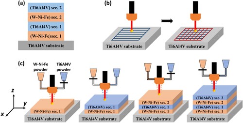
Table 1. Processing parameters of the DED processed Ti6Al4V/W7Ni3Fe alloy bimetallic layered structure.
2.2. Characterisation
A low-speed diamond saw (MTI, Richmond, CA) was utilised to cut the as-fabricated samples for exposing the cross-section. The sectioned samples were mounted with phenolic molding powder for the surface finishing. Surface finishing was then applied to the exposed cross-sections. The sectioned samples were ground by sandpapers with grits from 200 to 2000, then polished with Al2O3 suspension with particle sizes from 1 µm to 0.05 µm. Samples were immersed in a 100% ethanol solution and cleaned by an ultrasonicator for 20 mins.
2.2.1. Microstructure and phase analyses
Kroll’s reagent (92 mL of DI water, 6 mL of HNO3, and 2 mL of HF) was used to reveal the microstructure of Ti6Al4V-W7Ni3Fe bimetallic structure. The sample was fully immersed in Kroll’s reagent for 30 s. SEM obtained the microstructures at the cross-section of the fabricated bimetallic layered sample with both a secondary electron (SE) and a backscattered electron (BSE) detector. In addition, the elemental distribution at the samples’ cross-section was analyzed using energy-dispersive spectroscopy (EDS). X-ray diffraction (XRD) analysis was performed on the cross-section of the DED fabricated Ti6Al4V-W7Ni3Fe bimetallic structures using a Siemens D 500 Kristalloflex diffractometer. Cu-Kα was selected as a radiation source, a 2θ from 30 to 80 degrees and 0.05-degree step size were applied for analysis.
2.2.2. Microhardness test
The microhardness data at the cross-section was obtained from a microhardness tester (Phase II, NJ). At least ten indentations were applied across the interface and at the same depth. The hardness value at each depth was averaged based on the resulting measurements. The hardness test used a testing load of 1.96 N (HV0.2) and a dwell time of 15 s.
2.2.3. Thermal diffusivity test
The thermal diffusivity measurement of the DED processed Ti6Al4V-W7Ni3Fe bimetallic structures was performed using a Netzsch LFA 447 NanoFlash® thermal diffusivity system. In addition, specimens of Ti6Al4V substrate, DED processed pure W7Ni3Fe alloy, and DED processed pure Ti6Al4V were also tested to compare the results with the Ti6Al4V-W7Ni3Fe bimetallic structures. For all specimens, the thermal diffusivity measurements were obtained at 25°C and 50–300°C with 50°C increments. Three thermal diffusivity measurements were completed at each temperature point.
2.2.4. Compression test
The Ti6Al4V-W7Ni3Fe bimetallic layered structure was tested using a SHIMADZU AG-1S (50 KN) screw-driven universal testing machine. The bimetallic specimens for the compression tests were prepared with a square base (6 mm × 6 mm, length × width) and approximately 13 mm in height. The pure specimen dimensions varied slightly, with the samples having a height of ∼ 9 mm and side lengths that were ∼ 5 mm, which was to ensure that the tester did not exceed the 50 KN limit. The displacement rate for all the samples was 0.33 mm/min. At least 3 samples were tested under each test condition. Moreover, the specimens with both longitudinal and transverse orientations were tested.
3. Results and discussion
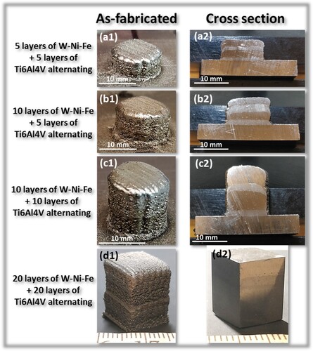
shows the images of the as-fabricated Ti6Al4V-W7Ni3Fe bimetallic samples and their cross-sections processed via the DED with different designs in the number of layers in each section. Specifically, (a1) and (a2) show the sample’s images of as-fabricated Ti6Al4V-W7Ni3Fe samples and cross-sections of the design having 5 layers of W7Ni3Fe + 5 layers of Ti6Al4V alternating. (b1) and (b2) show the sample’s images of the as-fabricated Ti6Al4V-W7Ni3Fe sample and its cross-section of the design with 10 layers of W7Ni3Fe + 5 layers of Ti6Al4V alternating. (c1) and (c2) show the sample’s images of the as-fabricated Ti6Al4V-W7Ni3Fe sample and its cross-section of the design with 10 layers of W7Ni3Fe + 10 layers of Ti6Al4V alternating. (d1) and (d2) show the sample’s images of the as-fabricated Ti6Al4V-W7Ni3Fe sample and its cross-section of the design with 20 layers of W7Ni3Fe + 20 layers of Ti6Al4V alternating. No visible defects or delamination were found in any samples, which proved the reliability of processing the Ti6Al4V-W7Ni3Fe bimetallic samples in different scales via the DED technique.
Figure 3. Images of the DED processed Ti6Al4V-W7Ni3Fe bimetallic layered structures and the cross-sections. (a) 5 layers of W7Ni3Fe + 5 layers of Ti6Al4V alternating (b) 10 layers of W7Ni3Fe + 5 layers of Ti6Al4V alternating (c) 10 layers of W7Ni3Fe + 10 layers of Ti6Al4V alternating (d) 20 layers of W7Ni3Fe + 20 layers of Ti6Al4V alternating.
The processing parameters selected for the W7Ni3Fe section and the Ti6Al4V section were optimised based on a series of experiments. To optimise the processing parameters for the W7Ni3Fe section, a laser power range from 250 W to 300 W was tested with a fixed powder feed rate of 48.6 g/min, a fixed laser scan speed of 600/min, and a fixed layer thickness of 0.25 mm. The results showed that the deposition could not form a W7Ni3Fe structure when the laser power was too low (∼ 250 W) or too high (∼300 W). Using a laser power of 270 W gave the best print result to build the pure W7Ni3Fe. However, the laser was out of focus after a certain number of layers were deposited with a laser power of 270 W, indicating incorrect layer thickness. After the layer thickness was adjusted to 0.22 mm, a tall W7Ni3Fe structure could be fabricated without laser focusing issues. The processing parameters for the Ti6Al4V section were obtained from the previous study (Afrouzian et al. Citation2022). The DED processed Ti6Al4V-W7Ni3Fe bimetallic samples were fabricated by applying the ‘direct deposition’ build strategy, which means that there is no functionally graded zone and only a small transition interface between the two materials as a result of the melting of the previous layers (Bandyopadhyay, Zhang, and Onuike Citation2022).
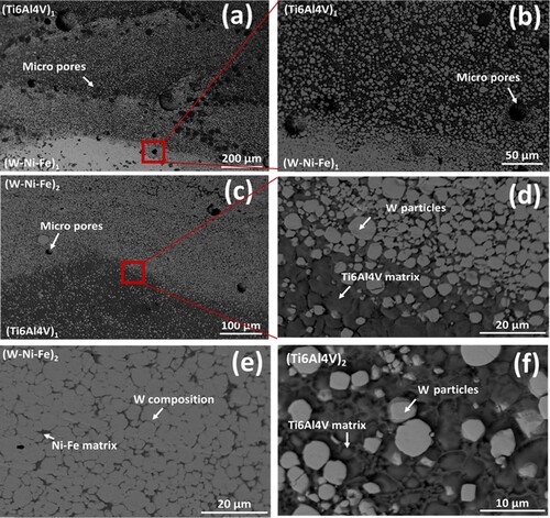
and reveal the microstructures of the DED processed Ti6Al4V-W7Ni3Fe bimetallic structure across each section. Specifically, a shows the microstructure at the bulk Ti6Al4V substrate. Coarse equiaxed grains (α-Ti) and discontinuous β-Ti can be seen. b and c are the SE and BSE-SEM images at the interface between the Ti6Al4V substrate and the W7Ni3Fe (sec. 1) section. Based on b, acicular Widmanstätten α-Ti laths were seen near the interface region of the Ti6Al4V substrate. The formation of acicular Widmanstätten α-Ti laths was caused by reheating and the rapid cooling rate by the laser deposition and scan motion on top of the substrate (Zhang et al. Citation2009). In c, the bright spherical microstructures were W composition. The spherical W particles were embedded in the Ni-Fe matrix, typically found in the LPS processed W7Ni3Fe (Gurwell et al. Citation1984; Srikanth and Upadhyaya Citation1984; Şahin Citation2014; Zhou et al. Citation2021). b and c show that no visible defects occurred at this interface. d illustrates the microstructure at the (W7Ni3Fe) sec. 1 section. A significantly higher volume fraction of W composition over the Ni-Fe composition was found in this section. Compared to c, the W particles in d coalesced and formed large W grains. Since the DED processing involves rapid solidification from the molten phase, the duration of a solution-reprecipitation in the W composition was extremely short. The W particle morphology results were smaller and less spheroidal than the W particle processed by conventional LPS methods due to the breaking of the agglomerated particles (Zhou et al. Citation2021). a and b show the BSE-SEM images at the interface between the (W7Ni3Fe) sec. 1 section and (Ti6Al4V) sec. 1 section. Micropores were found in this region, suggesting further optimisation of the processing parameters; however, some studies have developed efficient methods of optimising the parameters to obtain the lowest possible porosity (Rao et al. Citation2022). Although the DED system used in this study has two powder feeders, both powder feeders share the same powder feeding line. The W7Ni3Fe in the (Ti6Al4V) sec. 1 likely came from W7Ni3Fe particles that remained in the powder feeding line. No micro cracks could be found at this interface. c and d illustrate the morphology at the interface between the (Ti6Al4V) sec. 1 section and the (W7Ni3Fe) sec. 2 section. Micropores were again seen in the (W7Ni3Fe) sec. 2 sections near the interface. d is a magnified BSE-SEM image of the selected area from c. The spherical W particles were embedded in the polygon-shaped grains of the Ti6Al4V matrix. e shows the microstructure at the (W7Ni3Fe) sec. 2 section, similar to the morphology found in the (W7Ni3Fe) sec. 1 section (d). f demonstrates the microstructure at the (Ti6Al4V) sec. 2 sections, similar to the microstructure shown in d.
Figure 4. SEM images of the different microstructures present in the bimetallic. (a) Ti6Al4V substrate. (b) Ti6Al4V substrate/W7Ni3Fe interface (SE detector). (c) Ti6Al4V substrate/W7Ni3Fe interface (BSE detector). (d) W7Ni3Fe
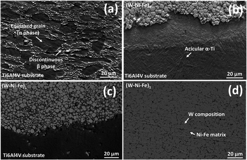
Figure 5. SEM image of the microstructure – (a) at the interface between the (W7Ni3Fe) sec. 1 section and the (Ti6Al4V) sec. 1 section (BSE detector). (b) Zoomed image of the selected area from (a); (c) at the interface between the (Ti6Al4V) sec. 1 section and the (W7Ni3Fe) sec. 2 section (BSE detector). (d) Zoomed image of the selected area from (c); (e) at the microstructure at the (W7Ni3Fe) sec. 2 section (BSE detector) and, (f) at the (Ti6Al4V) sec. 2 section (BSE detector).
The evolution of the W7Ni3Fe microstructure during the DED processing can be concluded in three stages: (a) rearrangement stage, (b) solution-reprecipitation, and (c) solid-state. The Ni-Fe and Ti6Al4V compositions are melted in the rearrangement stage due to the laser energy input, forming a small molten pool with W particles. The W particles are rearranged under the capillary force as in the DED process, and other forces, such as Marangoni force, buoyancy force, and the impact force from the powder carrier gas (Zhang et al. Citation2009; DebRoy et al. Citation2018). After the laser moves away, the dissolved W begins to reprecipitate at the solution-reprecipitation stage. The W can be reprecipitated either on residual W particles or forming individual nuclei in the liquid. Due to the rapid cooling rate of the DED process, the reprecipitated W grains could grow into irregular or dendritic shapes. Due to the rapid movement of the solidification front, the Ti6Al4V and Ni-Fe matrices grow into polygon shape grains. The powder carrier gas delivering the powders gathers and escapes from the molten pool. The powder carrier gas is trapped in the solidified molten pool during the solid-state stage due to the rapid solidification, resulting in micropore formation (Zhang et al. Citation2009).
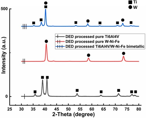
shows the EDS mapping of the Ti and W elements at the interfaces of the DED processed Ti6Al4V/W7Ni3Fe alloy bimetallic layered structure. Specifically, a shows the Ti and W elemental distributions at the interface between the Ti6Al4V substrate and the (W7Ni3Fe) sec. 1 section. b–d illustrate the EDS mapping at the interfaces between the (W7Ni3Fe)x and (Ti6Al4V)y sections. The remaining W particles could be seen in the (Ti6Al4V) sections. Moreover, the diffusion behaviour of the Ti/W elements at the interface was found. The mechanism of W diffusing into Ti was mainly due to the density difference between W and Ti, which causes W to sink into the Ti region (Zhang and Bandyopadhyay Citation2021). Furthermore, Ti diffuses into W through the defects of W, such as at dislocations and grain boundaries (Wang et al. Citation2021). The phase analysis was performed on the DED processed Ti6Al4V, W7Ni3Fe, Ti6Al4V/W7Ni3Fe bimetallic materials, shown in . Only Ti and W phases were detected in the DED processed Ti6Al4V-W7Ni3Fe bimetallic structures using XRD.
Figure 6. EDS mapping at the interfaces of the DED processed Ti6Al4V-W7Ni3Fe bimetallic layered structure (a) Ti6Al4V substrate and (W7Ni3Fe) sec. 1 (b) (W7Ni3Fe) sec. 1 and (Ti6Al4V) sec. 1 (c) (Ti6Al4V) sec. 1 and (W7Ni3Fe) sec. 2 (d) (W7Ni3Fe) sec. 2 and (Ti6Al4V) sec. 2.
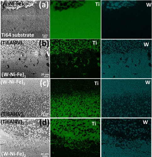
Figure 7. XRD results of the DED processed pure Ti6Al4V, W7Ni3Fe, and Ti6Al4V-W7Ni3Fe bimetallic materials.
a shows the hardness profiles across all the sections of the DED processed Ti6Al4V-W7Ni3Fe bimetallic layered structures. The Ti6Al4V substrate had a hardness of 315.2 ± 11.6 HV0.2. The microhardness value increased to 412.3 ± 43.6 HV0.2 near the interface between the Ti6Al4V substrate and (W7Ni3Fe) sec. 1 section. The increase in hardness was caused due to microstructural refinement. The hardness value of (W7Ni3Fe) sec. 1 near the interface between the Ti6Al4V substrate and (W7Ni3Fe) sec. 1 was 596.7 ± 34.6 HV0.2, and then decreased to 528.2 ± 27.5 HV0.2. According to c, spherical W particles were embedded in the Ni-Fe matrix at the first couple of deposited layers. The embedded W particles served as particle reinforcement, leading to higher hardness, but due to the hardness being higher than W7Ni3Fe, it suggests the formation of intermetallics despite the phases not showing up in the XRD analysis. These intermetallics are likely Ni-Ti compounds, as Ni and Ti are known to react with each other, especially in the case of bimetallic structures (Afrouzian et al. Citation2022; Farzaneh et al. Citation2022). In d, the W particles coalesced and formed large W grains. Based on the Hall-Petch relation, the grain size and hardness have a reverse proportional relation, which caused the drop in hardness. The microhardness value of the (W7Ni3Fe) sec. 1 section near the interface between (W7Ni3Fe) sec. 1 and (Ti6Al4V) sec. 1 was 517.5 7 ± 51.5 HV0.2, which had a similar hardness value to the previously measured region. The hardness value of the (Ti6Al4V) sec. 1 section at the interface between (W7Ni3Fe) sec. 1 and (Ti6Al4V) sec. 1 section was 544.5 ± 22.8 HV0.2. This hardness value was higher compared to the hardness value of the Ti6Al4V substrate. a and b show that the remaining W particles were embedded into the Ti6Al4V matrix. The increased hardness was caused due to W particle reinforcement and the intermetallic phase formations. The hardness further decreased to 475.4 ± 6.9 HV0.2, caused by less W particle reinforcement. The hardness of the (Ti6Al4V) sec. 1 section at the interface between the (Ti6Al4V) sec. 1 and (W7Ni3Fe) sec. 2 increased to 557.5 ± 30.0 HV0.2. The diffusion between the Ti and W near this region increased the hardness. The hardness of the (W7Ni3Fe) sec. 2 section followed the same trend as the hardness in the (W7Ni3Fe) sec. 1 section. Specifically, the hardness in the (W7Ni3Fe) sec. 2 section near the interface between the (Ti6Al4V) sec. 1 and (W7Ni3Fe) sec. 2 was 615.1 ± 41.7 HV0.2, and then the hardness dropped to 548.9 ± 20.7 HV0.2. The higher hardness near the interface region was caused by W/Ti diffusion and fine W particle reinforcement. The decrease in hardness resulted from the large grain formation (e). The hardness of the (W7Ni3Fe) sec. 2 near the interface between the (W7Ni3Fe) sec. 2 and (Ti6Al4V) sec. 2 was 563.6 ± 37.8 HV0.2. The hardness of the (Ti6Al4V) sec. 2 section also had a similar trend to the hardness of the (Ti6Al4V) sec. 1 section. The hardness of the (Ti6Al4V) sec. 2 near the interface between the (W7Ni3Fe) sec. 2 and (Ti6Al4V) sec. 2 was 546.1 ± 18.6 HV0.2, and then the hardness decreased to 504.3 ± 23.3 HV0.2.
Figure 8. (a) Hardness profiles of the DED processed Ti6Al4V/W7Ni3Fe alloy bimetallic, layered structures. (b) Thermal diffusivity as a function of temperature for the DED processed pure W7Ni3Fe alloy, Ti6Al4V/W7Ni3Fe bimetallic layered structure, and the DED processed pure Ti6Al4V.
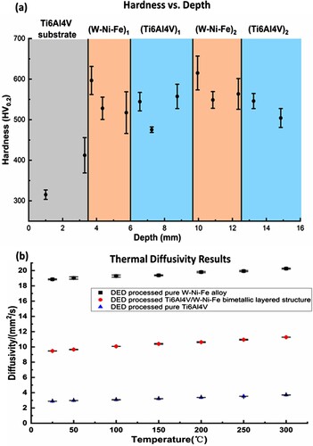
b shows the results of the thermal diffusivity measurements plotted as a function of temperature. The DED processed Ti6Al4V had the lowest thermal diffusivity values, ranging from 2.881 ± 0.002 mm2/s to 3.702 ± 0.014 mm2/s from 25 to 300°C. The DED processed pure W7Ni3Fe had the highest thermal diffusivity values, ranging from 18.853 ± 0.063 mm2/s to 20.258 ± 0.066 mm2/s from 25 to 300°C. The DED processed Ti6Al4V-W7Ni3Fe bimetallic layered structure showed thermal diffusivity values between the two base materials, ranging from 9.47 ± 0.015 mm2/s to 11.272 ± 0.007 mm2/s from 25 to 300°C. Based on the results, the thermal diffusivity of the Ti6Al4V-W7Ni3Fe bimetallic structure was approximately 3 times higher than the DED processed Ti6Al4V at 300°C. Additionally, the Ti6Al4V-W7Ni3Fe bimetallic structure showed a thermal diffusivity of about half of the DED processed pure W7Ni3Fe at 300°C.
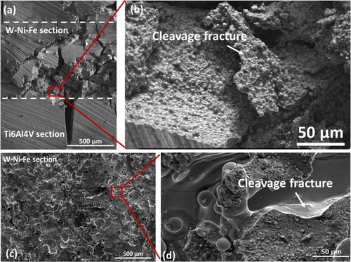
illustrates the results of the compression tests of Ti6Al4V-W7Ni3Fe bimetallic structures along the transverse and longitudinal directions, and the base Ti6Al4V and W7Ni3Fe alloys. The base Ti6Al4V samples performed the best out of all the samples in terms of failure strain, with the yield strength (884 ± 4.5 MPa) being very similar to the longitudinal bimetallic samples’ yield strength. For the W7Ni3Fe samples, the failure strain was ∼60% compared to Ti6Al4V and 64% (568 ± 60.7 MPa) yield strength. For the longitudinal samples, the formation of brittle intermetallics at the interfaces caused the failure strain to be only about 37% of the failure strain of Ti6Al4V, and the yield strength was about the same as Ti6Al4V. For the transverse samples, the failure strain was about 63% relative to Ti6Al4V, meaning that the failure strain fell between Ti6Al4V and W7Ni3Fe. Due to the intermetallic phase formation at the interfaces, the compression behaviour was unique, with multiples stages experienced during the deformation of Ti6Al4V-W7Ni3Fe bimetallic structures in the transverse direction (a–c). The first stage was the compression of the W7Ni3Fe section. In this stage, cracks were initiated and propagated in the horizontal direction of the W7Ni3Fe section due to cracks forming in the ductile matrix. a and b show the fractography of the transverse sample. After the compression test, brittle fracture and cleavage could be observed in the W7Ni3Fe region. The second stage was the compression of the Ti6Al4V. In this stage, micropores in the Ti6Al4V sections were compressed. Vertical cracks formed and penetrated the interfaces between the Ti6Al4V and W7Ni3Fe (a). These multi-stage compression behaviours could also be observed in the stress–strain curve of the transverse samples. However, the longitudinal samples of the Ti6Al4V-W7Ni3Fe structure only experienced a single-stage compression behaviour. According to d–f, the delamination occurred in the middle region at the interface between the Ti6Al4V-W7Ni3Fe, near the edge due to high-stress concentrations. The W7Ni3Fe section completely fell apart from the specimen after the compression test. In both samples, failure occurred at the interfaces. Based on c and d, transgranular cleavage fractography was seen in the W7Ni3Fe region of the longitudinal Ti6Al4V-W7Ni3Fe bimetallic structure after the compression test.
Figure 9. Stress (in MPa) and strain (in mm/mm) plots from the compression tests of the DED processed bimetallic Ti6Al4V-W7Ni3Fe structures in both transverse and longitudinal directions along with pure Ti6Al4V and W7Ni3Fe samples.
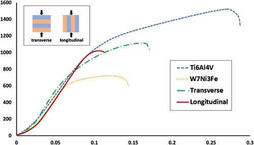
Figure 10. The DED processed Ti6Al4V-W7Ni3Fe bimetallic layered specimens for the compression tests (a) transverse sample (before compression testing); (b) transverse sample (during compression testing); (c) transverse sample (after compression testing); (d) longitudinal sample (before compression testing); (e) longitudinal sample (during compression testing); (f) longitudinal sample (after compression testing). The red lines denote the visible interfaces on the samples.
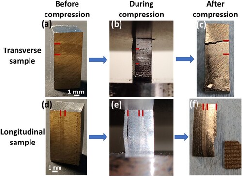
Figure 11. Fractography of the DED processed Ti6Al4V-W7Ni3Fe bimetallic, layered specimen – (a) transverse sample; (b) Zoomed image of the selected region from (a). (c) longitudinal sample; (d) Zoomed image of the selected region from (c).
4. Conclusions
This study aimed to fabricate Ti6Al4V-W7Ni3Fe bimetallic, layered structures via the DED-based metal AM. Bimetallic structures with multiple designs were fabricated with no visible defects at the interfaces between the Ti6Al4V and the W7Ni3Fe sections. Microstructural characterisation revealed unique morphology in each section. Specifically, coarse equiaxed grains were found at the Ti6Al4V substrate with discontinuous β-Ti. The microstructure of the W7Ni3Fe section near the interface between the Ti6Al4V substrate and the W7Ni3Fe section showed that spherical W particles were embedded in the Ni-Fe matrix. The microstructure of the W7Ni3Fe changed to large W grains as the deposition proceeded. The increased volume fraction of W composition was caused by the evaporation of Ni and Fe during the laser processing. The remaining W7Ni3Fe were found in the Ti6Al4V sections. The microstructure of the Ti6Al4V sections showed W particles embedded into the Ti6Al4V polygon matrix. The EDS mappings at the interfaces of the DED processed Ti6Al4V-W7Ni3Fe structure demonstrated the Ti/W diffusion. The XRD results showed no intermetallic phases formed in the DED processed Ti6Al4V-W7Ni3Fe bimetallic materials. According to the hardness measurements, the hardness value of the (W7Ni3Fe) sec. 2 section near the interface between the (Ti6Al4V) sec. 1 and the (W7Ni3Fe) sec. 2 showed the highest, 615.1 ± 41.7 HV0.2. The high hardness value in this region was caused by both Ti/W diffusion and W particle reinforcement and intermetallic phase formation. Based on the thermal diffusivity measurements, the DED processed Ti6Al4V-W7Ni3Fe structure showed three times higher thermal diffusivity than the DED processed Ti6Al4V at 300°C; and was about half of the thermal diffusivity value compared to the DED processed pure W7Ni3Fe at 300°C. The compression results showed multiple-stage deformation in the transverse sample and single-stage behaviour in the longitudinal sample. Additionally, both transverse and longitudinal fractography samples resulted in brittle cleavage at the W7Ni3Fe section. Our results show that the DED process can be used to manufacture layered bimetallic Ti6Al4V- W7Ni3Fe alloy structures with unique and tailorable mechanical and thermal properties.
Acknowledgments
The authors would like to acknowledge financial support from the National Science Foundation under grant number NSF-CMMI 1934230 and the Joint Center for Aerospace Technology Innovation (JCATI, Seattle, WA) grant in collaboration with the Boeing Company (Seattle, WA). The authors would also like to acknowledge financial support from JCDREAM (Seattle, WA) towards purchasing metal additive manufacturing facilities at WSU. The authors would also like to acknowledge Tungsten Parts Wyoming, Inc., for providing the tungsten powders used in this study.
Data availability statement
Data will be available upon request.
Disclosure statement
No potential conflict of interest was reported by the author(s).
Additional information
Funding
Notes on contributors
Yanning Zhang
Yanning Zhang received his BS in Materials Science and Engineering, MS in Mechanical Engineering, and Ph.D. in Mechanical Engineering (2021) from Washington State University (WSU). During his graduate studies at WSU, he worked on bimetallic structures using directed energy deposition-based metal additive manufacturing. He has published ten journal papers and is the inventor of one issued US patent. His work has been cited over 330 times, and the current “h” index is 8.
Cory Groden
Cory Groden is a MS candidate in the School of Mechanical Engineering at Washington State University. His research focuses mainly on the additive manufacturing of metals and bimetallic system using Directed Energy Deposition-based additive manufacturing, and the creation of mechanically efficient lattice structures using Powder Bed Fusion-based additive manufacturing.
E. Nyberg
E. Nyberg is a Metallurgist and Product Engineer at Kaiser Aluminum. Prior to this Mr. Nyberg was the Technology Development Manager at Tungsten Parts Wyoming, overseeing processing and materials development and the Quality Management System. Previously he was the Director of Programs at Brunel University, London, for the Brunel Centre for Advanced Solidification Technology (BCAST), leading the development of research programs with international partners. For 24 years Mr. Nyberg held a variety of roles at the Pacific Northwest National Laboratory (PNNL), most recently as Chief Engineer involving materials research and development. Mr. Nyberg received his M.S. and B.S. degrees in Materials Science and Engineering from Washington State University.
A. Bandyopadhyay
A. Bandyopadhyay is a Boeing Distinguished Professor in the School of Mechanical and Materials Engineering at Washington State University. He has worked with 22 Ph.D. and 30 MS students, an inventor of 21 issued patents, and published over 365 technical articles. His work has been cited over 30,000 times, and the current “h” index is 91 (Google Scholar as of October 20, 2022). He is a Fellow of the Society of Manufacturing Engineers, American Ceramic Society, ASM International, American Institute for Medical and Biological Engineering, American Association of Advancement of Science, National Academy of Inventors, and an elected member at the Washington State Academy of Science.
References
- Afrouzian, Ali, Cory J. Groden, David P. Field, Susmita Bose, and Amit Bandyopadhyay. 2022. “Additive Manufacturing of Ti-Ni Bimetallic Structures.” Materials & Design 215: 110461. doi:10.1016/j.matdes.2022.110461.
- Ang, Yao Ting, Swee Leong Sing, and Joel Choon Wee Lim. 2022. “Process Study for Directed Energy Deposition of 316L Stainless Steel with TiB2 Metal Matrix Composites.” Materials Science in Additive Manufacturing 1 (2): 13.
- Bandyopadhyay, A., K. D. Traxel, M. Lang, M. Juhasz, N. Eliaz, and S. Bose. 2022. “Alloy Design Via Additive Manufacturing: Advantages, Challenges, Applications and Perspectives.” Materials Today 52: 207–224. doi:10.1016/j.mattod.2021.11.026.
- Bandyopadhyay, A., Y. Zhang, and B. Onuike. 2022. “Additive Manufacturing of Bimetallic Structures.” Virtual and Physical Prototyping 17: 256–294. doi:10.1080/17452759.2022.2040738
- Bose, A., C. A. Schuh, J. C. Tobia, N. Tuncer, N. M. Mykulowycz, A. Preston, A. C. Barbati, et al. 2018. “Traditional and Additive Manufacturing of a New Tungsten Heavy Alloy Alternative.” International Journal of Refractory Metals and Hard Materials 73: 22–28. doi:10.1016/j.ijrmhm.2018.01.019.
- Cai, W. D., Y. Li, R. J. Dowding, F. A. Mohamed, and E. J. Lavernia. 1995. “A Review of Tungsten-Based Alloys as Kinetic Energy Penetrator Materials.” Reviews in Particulate Materials 3: 71–131.
- DebRoy, T., H. L. Wei, J. S. Zuback, T. Mukherjee, J. W. Elmer, J. O. Milewski, A. M. Beese, A. Wilson-Heid, A. De, and W. Zhang. 2018. “Additive Manufacturing of Metallic Components – Process, Structure and Properties.” Progress in Materials Science 92: 112–224. doi:10.1016/j.pmatsci.2017.10.001.
- Denti, L., E. Bassoli, A. Gatto, E. Santecchia, and P. Mengucci. 2019. “Fatigue Life and Microstructure of Additive Manufactured Ti6Al4V After Different Finishing Processes.” Materials Science and Engineering: A 755: 1–9. doi:10.1016/j.msea.2019.03.119.
- Farzaneh, Aidin, Mahyar Khorasani, Ehsan Farabi, Ian Gibson, Martin Leary, AmirHossein Ghasemi, and Bernard Rolfe. 2022. “Sandwich Structure Printing of Ti-Ni-Ti by Directed Energy Deposition.” Virtual and Physical Prototyping 17 (4): 1006–1030.
- German, R. M., P. Suri, and S. J. Park. 2009. “Review: Liquid Phase Sintering.” Journal of Materials Science 44: 1–39. doi:10.1007/s10853-008-3008-0.
- Groden, C., K. D. Traxel, A. Afrouzian, E. Nyberg, and A. Bandyopadhyay. 2022. “Inconel 718-W7Ni3Fe Bimetallic Structures Using Directed Energy Deposition-Based Additive Manufacturing.” Virtual and Physical Prototyping 17: 170–180. doi:10.1080/17452759.2022.2025673.
- Gurwell, W. E., R. G. Nelson, G. B. Dudder, and N. C. Davis. 1984. “Fabrication and Properties of Tungsten Heavy Metal Alloys Containing 30% to 90% Tungsten.” doi:10.2172/6390048.
- Li, Chun, Yingpei Wang, Shiyu Ma, Xiaoshan Yang, Jinfeng Li, Yuzhao Zhou, Xue Liu, Jingang Tang, Xiaoying Wang, and Guomin Le. 2020. “Densification, Microstructural Evolutions of 90W-7Ni-3Fe Tungsten Heavy Alloys During Laser Melting Deposition Process.” International Journal of Refractory Metals and Hard Materials 91: 105254. doi:10.1016/j.ijrmhm.2020.105254.
- Liu, Shunyu, and Yung C. Shin. 2019. “Additive Manufacturing of Ti6Al4V Alloy: A Review.” Materials & Design 164: 107552. doi:10.1016/j.matdes.2018.107552.
- Liu, J., L. Shukui, Z. Xiaoqing, Z. Zhaohui, Z. Haiyun, and W. Yingchun. 2008. “Adiabatic Shear Banding in a Tungsten Heavy Alloy Processed by hot-Hydrostatic Extrusion and Hot Torsion.” Scripta Materialia 59: 1271–1274. doi:10.1016/j.scriptamat.2008.08.036.
- Onuike, Bonny, and Amit Bandyopadhyay. 2018. “Additive Manufacturing of Inconel 718 – Ti6Al4V Bimetallic Structures.” Additive Manufacturing 22: 844–851. doi:10.1016/j.addma.2018.06.025.
- Onuike, B., and A. Bandyopadhyay. 2019. “Bond Strength Measurement for Additively Manufactured Inconel 718- GRCop84 Copper Alloy Bimetallic Joints.” Additive Manufacturing 27: 576–585. doi:10.1016/j.addma.2019.04.003.
- Onuike, B., and A. Bandyopadhyay. 2020. “Functional Bimetallic Joints of Ti6Al4V to SS410.” Additive Manufacturing 31: 100931. doi:10.1016/j.addma.2019.100931.
- Park, S., D.-K. Kim, S. Lee, D.-K. Kim, H. J. Ryu, H. J. Ryu, and S. H. Hong. 2001. “Dynamic Deformation Behavior of an Oxide-Dispersed Tungsten Heavy Alloy Fabricated by Mechanical Alloying.” Metallurgical and Materials Transactions A 32: 2011–2020. doi:10.1007/s11661-001-0013-1.
- Rao, Jing, Swee Leong Sing, Joel Choon Wee Lim, Wai Yee Yeong, Jizhong Yang, Zheng Fan, and Paul Hazell. 2022. “Detection and Characterisation of Defects in Directed Energy Deposited Multi-Material Components Using Full Waveform Inversion and Reverse Time Migration.” Virtual and Physical Prototyping 17 (4): 1047–1057.
- Rodriguez, O. L., P. G. Allison, W. R. Whittington, D. K. Francis, O. G. Rivera, K. Chou, X. Gong, T. M. Butler, and J. F. Burroughs. 2015. “Dynamic Tensile Behavior of Electron Beam Additive Manufactured Ti6Al4V.” Materials Science and Engineering: A 641: 323–327. doi:10.1016/j.msea.2015.06.069.
- Ryu, H. J., and S. H. Hong. 2003. “Fabrication and Properties of Mechanically Alloyed Oxide-Dispersed Tungsten Heavy Alloys.” Materials Science and Engineering: A 363: 179–184. doi:10.1016/S0921-5093(03)00641-5.
- Şahin, Y. 2014. “Recent Progress in Processing of Tungsten Heavy Alloys.” Journal of Powder Technology 2014: 1–22. doi:10.1155/2014/764306.
- Srikanth, V., and G. S. Upadhyaya. 1984. “Effect of Tungsten Particle Size on Sintered Properties of Heavy Alloys.” Powder Technology 39: 61–67. doi:10.1016/0032-5910(84)85020-2.
- Sunwoo, A., S. Groves, D. Goto, and H. Hopkins. 2006. “Effect of Matrix Alloy and Cold Swaging on Micro-Tensile Properties of Tungsten Heavy Alloys.” Materials Letters 60: 321–325. doi:10.1016/j.matlet.2005.08.050.
- Wang, S., M. Y. Xie, H. B. Huang, M. Kang, R. Liu, C. Chen, Z. Zhang, Z. H. Zhong, and Y. C. Wu. 2021. “Diffusion Behavior and Bending Fracture Mechanism of W/Ti Multilayer Composites.” Journal of Alloys and Compounds 879: 160451. doi:10.1016/j.jallcom.2021.160451.
- Wei, Chao, Han Ye, Zhuang Zhao, Jingang Tang, Xianfeng Shen, Guomin Le, Kun Ye, and Fangbin Le. 2021. “Microstructure and Fracture Behavior of 90W-7Ni-3Fe Alloy Fabricated by Laser Directed Energy Deposition.” Journal of Alloys and Compounds 865: 158975. doi:10.1016/j.jallcom.2021.158975.
- Ye, Han, Yibin Huang, Chao Wei, and Yaliang Liu. 2022. “Densification and Microstructure Formation Mechanisms of 80 W-14Ni-6Fe Fabricated by Laser Powder Bed Fusion.” Journal of Alloys and Compounds 909: 164684. doi:10.1016/j.jallcom.2022.164684.
- Zhang, Y., and A. Bandyopadhyay. 2019. “Direct Fabrication of Bimetallic Ti6Al4V+Al12Si Structures via Additive Manufacturing.” Additive Manufacturing 29: 100783. doi:10.1016/j.addma.2019.100783.
- Zhang, Y., and A. Bandyopadhyay. 2021. “Influence of Compositionally Graded Interface on Microstructure and Compressive Deformation of 316L Stainless Steel to Al12Si Aluminum Alloy Bimetallic Structures.” ACS Applied Materials & Interfaces 13: 9174–9185. doi:10.1021/acsami.0c21478.
- Zhang, S., X. Lin, J. Chen, and W. Huang. 2009. “Heat-treated Microstructure and Mechanical Properties of Laser Solid Forming Ti-6Al-4V Alloy.” Rare Metals 28: 537–544. doi:10.1007/s12598-009-0104-5.
- Zhou, S., Y. J. Liang, Y. Zhu, B. Wang, L. Wang, and Y. Xue. 2021. “Ultrashort-time Liquid Phase Sintering of High-Performance Fine-Grain Tungsten Heavy Alloys by Laser Additive Manufacturing.” Journal of Materials Science & Technology 90: 30–36. doi:10.1016/j.jmst.2021.02.032.