
 ?Mathematical formulae have been encoded as MathML and are displayed in this HTML version using MathJax in order to improve their display. Uncheck the box to turn MathJax off. This feature requires Javascript. Click on a formula to zoom.
ABSTRACT
Understanding powder bed system behaviour in powder spreading is a fundamental issue in binder jetting additive manufacturing (BJAM). This work established a discrete element model incorporating a parallel bond model to compatibly depict local cross-links between powder particles. BJAM parameters including layer thickness, gap compensation, recoat speed, rotation speed, and layer number were studied quantitatively for their effects on recoated powder's packing density and microscopic pore size and bonded layer's breakage and layer shift. Evolutions and influence mechanisms on both layer shift and bond breakage were further elucidated. Some practical implications include: gap compensation corresponding to an ideal recoated powder structure is ∼75 μm; rotation speed should be controlled at 40–120 rad/s to avoid low-rotation-speed layer shift surge and high-rotation-speed breakage; layer shift occurring at a certain stage is irreversible and must deserve well-maintained. This research can provide theoretical guidance for developing BJAM and even support-free powder bed – based additive manufacturing.
1. Introduction
Binder jetting additive manufacturing (BJAM), one of the powder bed – based additive manufacturing (AM) processes, has become popular recently due to its advantages of high speed, low cost, large quantity, and broad material compatibility (Ziaee and Crane Citation2019; Mostafaei et al. Citation2021; Liravi and Vlasea Citation2018; Lv et al. Citation2019; Ma et al. Citation2020; Sivarupan et al. Citation2021). Some typical materials that can be fabricated via BJAM include metals, ceramics, biomaterials, and polymers (Zhou et al. Citation2020; Xu et al. Citation2020; Stevens et al. Citation2021; Nandwana, Kannan, and Siddel Citation2020; Rodríguez-González et al. Citation2020; Martin et al. Citation2021; Cramer et al. Citation2019). BJAM jets binders to bond powder particles into parts without the production of residual stress and the addition of support structures. Besides binder injection, BJAM process also contains stages of binder curing, debinding, and sintering (the latter two are optional for metals and ceramics) (Chen et al. Citation2019; Li et al. Citation2021). Currently, the main challenges in BJAM are the improvement of dimensional accuracy and mechanical strength in green part fabricating and the shrinkage control in a sintering stage. In the binder injection stage, array piezoelectric nozzles are used to selectively jet binder droplets at a high speed in a layer-by-layer manner until the printing of a green part is completed. In the binder curing stage, an appropriate strategy is used to cure the jetted binder (waterborne, solvent-based, or ultraviolet curable) to strengthen the green part (Wilts and Long Citation2020), which can achieve a compressive strength of 1 – 25 MPa (Oropeza Gomez Citation2021; Manotham et al. Citation2021; Gilmer et al. Citation2020; Mao et al. Citation2021). During the debinding and sintering stages, the binder is removed with thermal decomposition in a vacuum furnace, and then the green part is sintered into a final dense part.
To facilitate a narrative, we classified the timing of binder curing in BJAM as integral-curing, real-time curing, and mixed-curing (i.e. a combination of the former two) (Sachs et al. Citation1994; Gilmer et al. Citation2020; Liravi and Vlasea Citation2018; Manotham et al. Citation2021). Integral-curing BJAM requires a long-time binder curing after the printing job to achieve a final strength, which may consume a few hours of baking in a drying oven or just more than ten hours of placement. Compared to integral-curing BJAM, real-time curing BJAM alternates the binder injection and the binder curing stages between adjacent layers; after jetted and penetrated, the binder droplets among the powder immediately receive a stimulus, such as ultraviolet irradiation, infrared irradiation, or a cross-linking inducer, leading to the new cross-links between the recoated powder and the previous bonded layer (Manotham et al. Citation2021; Deng et al. Citation2022; Manotham and Tesavibul Citation2022; Nanthananon et al. Citation2021). Regarding mixed-curing BJAM, the injected binder experiences partial curing during the printing and needs a final curing process like integral-curing BJAM. Real-time curing BJAM thus has a potential brighter prospect due to a shorter operating route, a more time-saving cost, and a lower economic cost than the other two that are the current mainstream of BJAM.
On the other hand, real-time curing BJAM can also encounter a more complex physical interaction among the recoater (usually a roller), recoated powder, and bonded layer than integral-curing and mixed-curing BJAMs. Comparatively, integral-curing and mixed-curing BJAMs naturally do not involve breakage and warpage problems during the powder recoating process in which the jetted binders penetrate and then achieve an equilibrium state among the unbonded powder layer due to gravity and capillary force (Deng et al. Citation2022). As we know, a poor powder spreading process can result in layer defects (Mariani et al. Citation2021; Ma et al. Citation2020; Miao et al. Citation2020; Phua et al. Citation2021; Mussatto et al. Citation2021) such as a layer shift (Maximenko et al. Citation2021), a bond breakage, an insufficient packing density of the recoated powder, and a warpage due to uneven curing of binder (Sheydaeian et al. Citation2017; Schmutzler, Stiehl, and Zaeh Citation2019), which can finally deteriorate the quality of green parts and the latter sintered parts. Compared with additive manufacturing techniques having support structures, those support-free additive manufacturing techniques can suffer a more severe disturbance on print layer from the recoater during powder spreading due to a missing anchor from support structures; a well-controlled powder spreading behaviour is hence more essential to the support-free additive manufacturing. Moreover, the Sapphire solution from Velo3D has surprisingly achieved a support-free SLM fabricating of parts with 0-degree overhangs through systematic in-situ thermal monitoring of the printing process and real-time printing parameter correction as well as using a non-contact powder coating method (Weber et al. Citation2021). This advance in SLM also conveys that revealing the powder spreading mechanisms in real-time curing BJAM is of great significance for exploring and developing BJAM.
An experimental investigation of the powder spreading behaviour can encounter the following difficulties: (1) obtaining information about micron-sized powder particles through sensors (Escano et al. Citation2018; Escano et al. Citation2019; Penny et al. Citation2021; Tan et al. Citation2021); (2) operating and testing of many actual conditions (Tan et al. Citation2021); (3) quantitative characterisation and quality evaluation of a specific layer (Penny et al. Citation2021; Mamun et al. Citation2022); (4) higher cost when increasing the complexity and precision of the measurement task. Excelling at the numerical calculation of the macroscopic discontinuous medium system, the discrete element method (DEM) could provide more systematic information than experiments and is widely used in the powder spreading simulation in the powder bed – based AM (Yao et al. Citation2021; Meier et al. Citation2019; Chen et al. Citation2019; Chen and Yan Citation2020; Chen et al. Citation2020). Regarding BJAM, previous experimental and computational studies mainly focus on the powder spreading of integral-curing and mixed-curing BJAMs (Lee, Nandwana, and Simunovic Citation2021; Mariani et al. Citation2021; Clares and Manogharan Citation2021; Lee, Nandwana, and Zhang Citation2018). However, there are few studies conducted for real-time curing BJAM, and the only related literature is that Desai et al. introduced a non-local bonding DEM model yet gave a preliminary validation of the shear-induced deformation (Desai and Iii Citation2021).
Herein, the DEM incorporating the constitutive relationships of the Hertz-Mindlin with JKR cohesion model (Johnson, Kendall, and Roberts Citation1971) and parallel bond model (PBM) (Potyondy and Cundall Citation2004) was first used to explore the powder spreading process in real-time curing BJAM. The PBM superimposed on a base contact model can bond particles with a limited size bond that resists tangential and normal motion until maximum normal and tangential shear stresses are reached; thereafter, the particles are completely governed by the base contact model interacting as hard spheres. The effects of layer thickness, recoat speed and rotation speed of a roller, gap compensation, and layer number on powder spreading behaviour, including packing density and microscopic pore size of the recoated powder and bond integrity and layer shift of the bonded layers, were quantitatively elucidated using orthogonal and one-way methods. The underlying mechanisms of the interaction among the roller, powder particles, and the in-situ bonded layers were unveiled. This research can provide a valuable theoretical contribution to understanding the powder behaviours in real-time curing BJAM and the further development of BJAM.
2. Methodology
2.1. Powder spreading approach in real-time curing BJAM
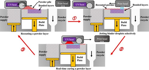
The powder spreading approach in BJAM has evolved from early piston feeding with roller spreading to current hopper feeding with roller spreading (Oropeza Gomez Citation2021; Oropeza, Roberts, and Hart Citation2021; Mostafaei et al. Citation2021). The former method supplying all powder required for a specific layer by lifting a layer thickness height of a piston at one time is suitable for fabricating parts with a small cross-section (Cao et al. Citation2015). In contrast, the latter method contactlessly feeding the powder required for a layer from the hopper onto the powder bed during a recoat movement of the hopper is suitable for the fabrication of parts with a large cross-section, and it has a higher recoat efficiency and a higher forming quality. It should be noted that those powder spreading approaches require a roller for further spreading and compaction, the rotation direction of the roller is counterclockwise (Chen et al. Citation2020), and the apparent difference among them is the spatial distribution and amount of the powder piles to be spread. schematically depicts a typical printing cycle of a layer during real-time curing BJAM using a feeding piston and a roller recoater.
Figure 1. Layer-by-layer fabricating steps of green parts in real-time curing BJAM.
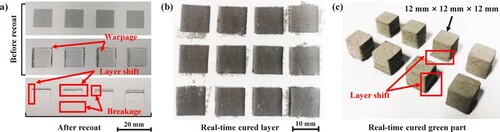
presents that the 316L green parts fabricated by an in-house developed BJAM machine with the real-time curing function suffered from the typical defects such as layer shift, breakage of bonded layer, and even warpage. Note that layer shift is a layer wise defect, which refers to the movement of the unanchored binder-powder system away from the ideal spatial position along the powder spreading direction ((a)). Although the layer shift decreases with the layer number, the accumulation of the layer shift eventually leads to macroscopic geometric deformation, typically with a deformed bottom and a normal top of the green part ((c)). Additionally, the ultraviolet curable binder mainly containing acrylate oligomer, monomer, and photoinitiator was real-time cured using an ultraviolet lamp with a central wavelength of 395nm.
Figure 2. Typical vital defects in real-time curing BJAM: (a) real-time cured layers during printing (inside powder bed); (b-c) real-time cured layers and green parts after an ultraviolet irradiation (outside powder bed).
2.2. DEM modelling for real-time curing BJAM
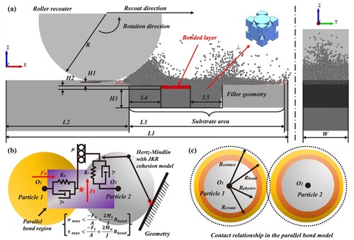
A DEM numerical model was established based on the EDEM software to reveal the powder spreading behaviours in real-time curing BJAM, as schematised in . (a) depicts a DEM environment that ignores powder feeding components (such as hopper and piston) and mainly includes a roller, necessary equipment geometry, and critical geometry dimensions. Additionally, a slope was arranged at the initial contact position between the roller and the powder bed to smooth the disturbances caused by the geometric discontinuities. Moreover, a filler geometry substituted a portion of the powder bed ((a)), which can reduce redundant particles and improve the calculation speed.
Figure 3. DEM setup of powder spreading in real-time curing BJAM: (a) DEM environment; (b) contact constitutive model; (c) radii compatibility relationship in PBM. Parameters (1.5 mm),
(9.15 mm),
(4 mm),
(5 mm),
(1 mm), and
(1 mm) are the depth and length of the computational domain, a distance from the powder bed to the left, a recoating length, two distances from the bonded layer to the left and right of the powder bed, respectively;
,
, and
(0.75 mm) are a gap height, a layer thickness, and a distance from the upper surface of the bonded layer to the substrate, respectively; and
(2 mm) is the radius of the roller recoating along the X-axis and rotating in a counterclockwise direction in a local coordinate system.
316L stainless steel was chosen as the material for the powder particles and geometries as in previous work (Yao et al. Citation2021; Chen et al. Citation2019; Chen and Yan Citation2020). A powder particle size of 50 μm is regarded as a critical value; the adhesion force between powders will increase with decreasing particle size, becoming the primary component affecting the collision behaviour at less than 50 μm, while the powder mobility will be better beyond it (Ziaee and Crane Citation2019; Chen, Li, and Yang Citation2015); 53 μm is a typical commercial powder particle size division value and also a standard sieve mesh size according to ASTM E11. The 316L powder particles are thus idealised to near-average sized spherical particles as peers (Yao et al. Citation2021; Fouda and Bayly Citation2019) with a 53 μm diameter, which can avoid small particles thus significantly speeding up calculation and balance adequate physical representativeness. The particles within the initial powder bed and feeding powder pile were programmatically created following the coordinates in a face-centre-cubic (FCC) sphere packing for a high packing density. The coordinates were calculated as.
(1)
(1) where
,
, and
are row and column numbers within an intra-layer, and layer number of the packing particle, respectively, and
,
, and
all take the values of {0,1,2 … } respectively;
is the creation radius of particles ((c));
sign indicates a remainder operation. The programmatical creation at the initial time step can considerably reduce the time consumed compared with the falling and spreading way to create piles and powder beds. Note that the excessive regular packing of FCC may impose a certain restriction on the particle movement (in the x-direction) especially for the particles located at the bottom of the powder bed. So a particle diameter gap is artificially placed between the substitute particles and their surroundings to introduce a certain degree of freedom for the powder bed to alleviate the potential limitation of the regular FCC packing on the horizontal movement of the particles, which makes the powder bed around the bonded layer closer to the reality (an uneven distribution of pores). The following filling of this gap by surrounding particles during powder spreading will prevent this practice from causing a large deviation.
Newton's laws of motion and the contact constitutive model revealing the essence of interactions among different particles are the two critical components in DEM calculation. A particle in DEM undergoes both motions of translation and rotation, governed by Newton's second law,
(2)
(2) where
,
,,
,
,
are the mass, radius, moment of inertia, position vector, and angular displacement of the i-th particle, respectively; and
,
,
,
,
are the total contact force, the total moment, the normal and tangential components of contact force, and cohesion force from the j-th adjacent particle on the i-th particle, respectively. Simple contact models are usually combined and developed into refined ones to obtain a credible result. Then, a particle's forces, velocities, and position can be updated based on those of the particles contacted with it from the last timestep.
The Hertz-Mindlin model can describe the interaction among ideal powder particles, while an actual powder particle often has an adhesive force due to the Van der Waals force. Therefore, the Hertz-Mindlin with JKR cohesion model embracing an adhesion force is commonly utilised for the powder spreading simulation (Johnson, Kendall, and Roberts Citation1971). However, in real-time curing BJAM, the unbonded powder is immediately bonded together with the binder droplets penetrating among them. The pure Hertz-Mindlin with JKR cohesion model is unable to characterise the interaction between bonded layers and unbonded powder, and the PBM provides an applicable supplement (Qu et al. Citation2020).
(b) schematically depicts the utilised contact model, which retains a model of Hertz-Mindlin with JKR cohesion and introduces a supplementary PBM to establish the strength of bonded layers; further illustrates the detailed DEM modelling and calculation workflow. Regarding action timing and region, the Hertz-Mindlin with JKR cohesion model acts on all powders and engages all time steps, while the PBM only works on target bonded particle region and from a specific time step onwards. Two particle types with same physical parameters, called Type-1 and Type-2, are introduced to distinct the unbonded and bonded powder regions. For implementation, EDEM's built-in Hertz-Mindlin with JKR cohesion (containing standard rolling friction) is adopted as the base contact model, which covers all particles’ contacts; the PBM, covering contacts only between Type-2 and Type-2 particles, was developed with EDEM-API using Microsoft Visual C++ into a user define library (UDL).DLL plugin along with other simulation-related modules to efficiently create powder bed and timing-specific curing bonding. The UDL's functions include loading parameters, generating powder bed and pile, replacing particles, and calculating PBM at the desired time step; all parameters except the powder spreading parameters including powder bed and pile data, PBM microscopic parameters, and particle replacement region data were configured in a .txt file. Finally, after a bond is set, its record is maintained in the data list of both particles in contact until the normal or tangential stress in this bond exceeds a given critical stress threshold. Moreover, the forces and torques on the particles in this model are calculated by.
(3)
(3) where
and
are the contact force and contact moment received from the j-th adjacent particle on the i-th particle;
and
are the contact force and contact moment received from a bond in the direction of the j-th adjacent particle on the i-th particle. Additionally, shows more detailed equations contained in the constitutive relationship (Yao et al. Citation2021; Chen et al. Citation2019; Potyondy and Cundall Citation2004).
Figure 4. Detailed DEM modelling and calculation workflow for BJAM powder spreading.
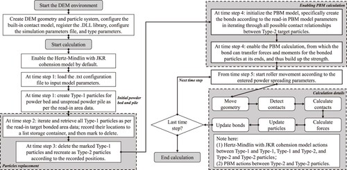
Table 1. Contact constitutive equations used in the powder spreading simulation.
In , ,
,
,
,
are contact radius, surface energy density, total overlap, normal overlap, and tangential overlap, respectively;
,
,
,
,
,
,
are the normal and tangential relative velocities of the i-th particle in the direction of the j-th particle, coefficients of static friction and rolling friction, coefficient of restitution, a distance from contact point to the centre of mass, and an angular velocity of a particle at the contact point, respectively;
,
,
,
,
,
are timestep, the radius of the bond, normal and shear stiffnesses, and angular velocities in normal and tangential directions, respectively; additionally, equivalents of mass, radius, Young’s modulus, and shear modulus are defined as
,
,
, and
, respectively;
,
,
,
,
,
,
,
,
, and
are mass, radius, Young’s modulus, shear modulus, and Poisson’s ratio of i-th and j-th particles, respectively.
2.3. Parameter determinations in the DEM model
In DEM, the explicit numerical solver of the central difference time integration scheme faces no divergence but a stability problem when an excessive timestep is used. Accordingly, the Rayleigh critical timestep limit () (O’Sullivan and Bray Citation2004; Chen et al. Citation2019) can give a guide for the timestep, which is provided by.
(4)
(4) where
,
, and
are density, Young's modulus, and radius of the particles, indicating that a smaller particle radius and a bigger Young's modulus lead to a shorter timestep. An increase in the particle number within the computational domain increases the computation time per timestep. Consequently, the timestep with an original Young's modulus and a radius in a micrometer scale will lead to an ns-level timestep, resulting in an unrealistic long computation time. The reduced particle stiffness method (RPS) scaling down the original Young's modulus and compensating with an adjusted surface energy density
gives a good solution (Hærvig et al. Citation2017), as described by
(5)
(5)
where and
are the modified value of surface energy density and Young's modulus. Here, if the surface energy is not adjusted, reducing only the Young's modulus will lead to an inevitable larger overlap between the colliding particles, further resulting in more work to overcome the adhesive force (Hærvig et al. Citation2017). According to Young's equations, the interfacial energies between the solid, liquid, and gas phases jointly determines the contact angle of the fluid on the solid surface; therefore, the adjusted surface energy will inevitably affect the wetting effect of the binder fluid on the powder surface, which in turn can affect the penetration and the final equilibrium distribution of the binder fluid among the powder bed governed by the Navier-Stokes equations. This physical process is usually complex and model-dependent and usually needs to be revealed via computational fluid dynamics methods (Fuchs et al. Citation2022; Deng et al. Citation2022). Therefore, in this work, the penetration, capillarity and equilibrium of the binder droplets on the powder bed and the details of their influence on the bond strength are not considered; however, the macroscopic strength of the bonded particles should match the experimental and literature values, otherwise the adopted reduced Young's modulus with the corresponding surface energy density may not be reasonable. Finally, this work assumes that the jetted binder has completed uniform penetration equilibrium in the target bonded powder region, and further employs parallel bond in the PBM model to characterise the real-time cured binder and its effects. Note that parameters for the part of the Hertz-Mindlin with JKR cohesion model keep consistent with that published in previous works (Yao et al. Citation2021), as shown in . Additionally, the adopted Young's modulus (Yao et al. Citation2021) of the particle is three orders of magnitude lower than the original value (2.2e11 MPa) of the material.
Table 2. Description and value of parameters in the BJAM simulation system.
To ensure the successful creation of parallel bonds and give reasonable parameters in PBM, a set of critical radii was hereafter introduced, and their compatibility relationship was illustrated. (c) schematically depicts those radii associated with two adjacent particles, which involves physics radius (), creation radius of particles (
), creation radius of bonds (
), and contact radius of bond (
). Additionally, the radius of physics is equal to the radius of the particle;
is used when particles are programmatically created (EquationEq. (1)
(1)
(1) ), and it is slightly larger than
to prevent an overlapping leading to an error and interruption; the
is used when a bond is formed, and only the adjacent particles within the limit region of
can form a bond between them;
is the basis for determining whether there is a contact relationship between two adjacent particles in the DEM software; moreover, the contact relationship and its related contact data will be deleted from the computer's memory if
exceeds the threshold. Finally, the compatibility relationship of those four radii should be in the order of.
(6)
(6) The values of those radii are shown in . Note that
should be larger but as close as possible to
to avoid an enormous collapse in the initial stage of simulation;
should be greater than
to ensure the successful creation of the particle bond.
The determination relationship from PBM parameters to the macroscopic mechanical response is complex and inconclusive due to the complicated particle packing structure, particle material property parameters and the PBM parameters themselves (Hanley et al. Citation2011). Both powder particle size distribution and the overall packing density affect particle coordination number and contact force chain distribution, further influencing the mapping characteristics (Schöpfer et al. Citation2009). Therefore, using the one-factor-at-a-time (OFAT) method, a series of unconstrained uniaxial compression simulations (UCSs) of cubic specimens was conducted to explore the influence of microscopic parameters in PBM on the macroscopic stress–strain response. The compression strength can be further calculated from the obtained stress–strain data to determine whether the response is suitably representative of the bonded layer in BJAM. The set of , independences of specimen size and loading speed of an indenter, and microscopic parameters in PBM were investigated in the UCSs. The combination of microscopic parameters contains critical normal stress (
), critical tangential shear stress (
), normal stiffness (
), tangential stiffness (
), and bond disk radius (
) (Qu et al. Citation2020; Tamás, Kovács, and Jóri Citation2016). Normal and tangential stiffnesses (
,
) were kept the same to reduce the complexity of parameter configuration, and particles within the specimen were created programmatically.
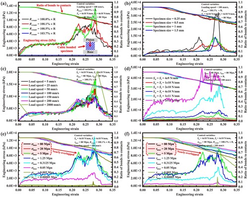
presents the macroscopic stress–strain responses of those UCSs. The UCS setup is also schematically presented at the lower right corner of (a). Here, the different size cubic specimen is initially FCC packed with mono-diameter particles as EquationEquation 5(5)
(5) with a particle number between 108–28899; then bonds between the particles are formed according to the PBM parameters at the next time step, and then the indenter is loaded at the loading speed until the end. The displacement and loading force of the indenter for each saved time step were extracted using a python script based on EDEM-API. (a) indicates that a
less than a threshold of
leads to no difference in macroscopic response, while a bigger one leads to a disappearance of strength due to the unsuccessful bond creation. (b) shows that those UCS responses having a similar yield strength become smoother when the side length of the sample increased from 0.25–1.5 mm; moreover, the response before the strain of 0.025 experienced an elastic stage and then encountered a yield stage. The evolution of the ratio of survived bonds also proved that. (c) shows a loading speed taken from 5 to 200 mm/s leading to a slight difference in macroscopic response. (d) indicates that
and
can decisively affect the macroscopic yield strength in a positive correlation. (e – f) show that both
and
can significantly affect the yield strength similarly; additionally, that effect on the yield strength can be redundant when both
and
are higher than a threshold. Note that
, the side length of the sample, and loading speed in (d – f) were controlled as (1 + 0.1%)R, 0.5 mm, and 100 mm/s, respectively; and
was equalled to
.
Figure 5. Macroscopic stress-strain responses of a series of UCSs for determining microscopic parameters within PBM: (a) creation radius of particles; (b) specimen size; (c) loading speed; (d) normal and tangential stiffnesses; (e) critical normal stress; (f) critical tangential shear stress. The top lines refer to the ratio of unbroken bonds to initial total contacts within the specimen, which can intuitively reflect the dynamic establishment and bond breakage during UCS.
The particles number in UCS model (1014 particles for a cubic specimen with a 0.5 mm length) is much smaller than that in formal BJAM simulation (∼39500 particles), and thus using the original Young's modulus (2.2e11 MPa) instead of the reduced one in UCS leads to an acceptable increased computational time cost. Additionally, this approach helps to obtain a closer compression behaviour to the actual bonded particle, thus providing us with a more informative and realistic reference; it can also avoid the calibration complexity with the modified stiffness and surface energy density themselves. Notably, the compressive strength of BJAM green parts lies in a range of 1 – 25 MPa due to different binder compositions and curing conditions, which is much lower than that in other fields where a PBM model is employed (Oropeza Gomez Citation2021; Gilmer et al. Citation2020; Mao et al. Citation2021; Qu et al. Citation2020). Furthermore, the parameter calibration focuses on obtaining PBM parameters whose macroscopic response is representative of the BJAM cured powder, rather than obtaining the exact PBM parameters whose UCS response is so close to a certain compression strength (1.5, 10.5 MPa, or other). Combined with the results from , the target compressive strength of bonded particles was defined as 1.5 MPa. Surely, the UCS response obtained using the original Young's modulus is inevitably different from that using the reduced one; so another compressive simulation adopting an adjusted Young's modulus was conducted to verify the obtained reference PBM parameters, in which the obtained compressive strength of 10.5 MPa is also lying in the range of 1–25 MPa. This indicates the PBM parameters should be reasonably representative and acceptable for the BJAM process. And we can further infer that, in the formal BJAM powder spreading simulation, the breakage degree of bonded layer using reduced Young's modulus should be less than that using the original one (corresponding to 1.5 MPa), but the difference in layer shift and packing density is not significant. The final determined PBM parameters are presented in .
2.4. Variable considerations and quantitative characterisations
The parameters in controlling the powder spreading of BJAM include layer thickness, recoat speed and rotation speed of the roller, traverse speed (optional) and vibration intensity (optional) of the hopper, and even radius and surface texture of the roller (Oropeza Gomez Citation2021; Oropeza, Roberts, and Hart Citation2021). This work considered only the general and basic parameters of layer thickness, recoat speed, rotation speed, gap compensation, and layer number. In actual powder spreading, the average height of the newly recoated powder surface is usually lower than the roller's bottom in powder spreading, and there is a gap between them (Rosala Citation2021); both powder spreading parameters and powder mobility can affect the gap magnitude. As illustrated in , the gap compensation parameter is thus introduced in this study based on this phenomenon, which helps to a more comprehensively controlling for powder spreading and to a wider process window of spreading parameters. Therefore, the gap height, which represents the distance from the roller's lower edge to the upper surface of the bonded layer, should not simply take the value as layer thickness but be compensated instead. Gap compensation physically means the fine adjustment amount of the gap height. And its setting can be engineering implemented all at once before the formal powder spreading (before printing). The relationship between gap height (), gap compensation (
), and layer thickness (
) can be described by.
(7)
(7)
To obtain the desirable candidate combinations of the above variables and their respective effects and to fully explore the effects of gap compensation on spreading powder, we performed five series of independent orthogonal simulations (according to ) for each of the five different gap compensations (0, 25, 50, 75, and 100 μm), and a total of 80 simulations were carried out. The level intervals for layer thickness, moving speed, and rotation speed were 70–190 μm, 25–100 mm/s, and 0–120 rad/s, respectively. The output characteristics of the DOE listed in are the packing density of newly recoated powder and both the bond integrity and layer shift of bonded layer. Based on the desirable candidate parameter combinations, detailed one-way simulations were conducted to further study the behaviour of powder particle systems during powder spreading of real-time curing BJAM.
Figure 6. Schematic diagram of the relationship among layer thickness, gap height, and gap compensation.
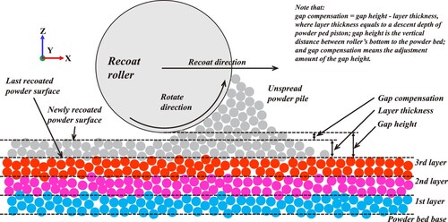
Table 3. Orthogonal design with three factors and four levels for arranging DEM simulations (43).
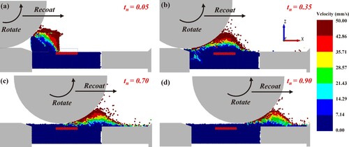
Regarding the quantitative characterisation of the powder spreading process in real-time curing BJAM, bond breakage and layer shift were quantified to characterise bonded layer, and packing density and pore size distribution were for recoated powder. To characterise roller positions at varied recoating speeds when recoating a specific length, the normalised time () of each simulation is employed and determined by
, where
and
are a specific time and a total recoating time, respectively. presents DEM simulation scenarios of BJAM powder spreading. The evolution and influence mechanisms of layer shift and bond breakage were further illustrated through force analysis.
Figure 7. DEM simulation scenarios of BJAM powder spreading (recoat speed of 25 mm/s; rotation speed of 80 rad/s), corresponding to typical normalised time, respectively, (a) at normalised time 0.05; (b) at normalised time 0.35; (c) at normalised time 0.70; (d) at normalised time 0.90.
3. Results and discussion
3.1. A preliminary study based on orthogonal designed simulations
3.1.1. Packing density and packing structure of recoated powder
The packing performance of recoated powder is the most fundamental judgment to evaluate the behaviour of BJAM spreading process, which is directly related to the densities and the mechanical properties of the green parts and even the final sintered parts. Packing density () is a widely used variable to characterise packing performance, as calculated by (Chen et al. Citation2019; Yao et al. Citation2021)
(8)
(8) Here,
is a volume sum of particles contained in a target layer region, and
is the volume of this region; the target layer region is located above the ideal bonded layer, which has a same bottom surface as the bonded layer and a height equal to a layer thickness. The
is calculated as:
, where a and b are the width and length of the bonded region, and
is the layer thickness. The
is calculated as:
, where r is the powder particle radius and
is the number of newly layered powder particles contained in the target region. The open-source C++ library Voro++ was utilised to compute the Voronoi tessellation (Rycroft Citation2009), and POS-RAY software rendered the Voronoi diagram ((a)).
Figure 8. Packing structures of typical packing densities: (a) frontal Voronoi diagram of spread powder layer; (b) top views of spread powder layer morphology, where the left purple area refers to bonded layer (bonded particles).
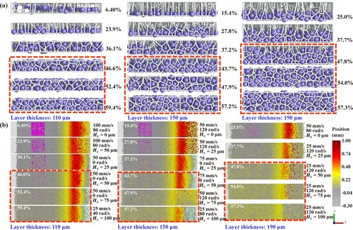
The front and top views of typical packing densities with different layer thickness values (110, 150, and 190 μm) are presented in (a-b). (a) shows that reasonable packing density for the layer thicknesses of 110, 150, and 190 μm should be between 46.6% – 59.4%, 43.7% – 57.2%, and 47.8% – 57.3%, respectively, which agrees with the peer study (Ziaee and Crane Citation2019). Almost no excessive particles transcend the target region within a newly recoated powder layer, and the Voronoi tessellation with excessive porosity is nonexistent. Moreover, (b) presented that the optimum packing density range has better coverage for the previously printed layer. Those results also indicate that configuring the powder spreading parameters can obtain a close to 60% packing density.
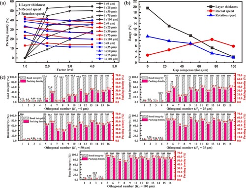
The within-level means of packing density for all three factors with five gap compensations are displayed in (a). Each within-level mean of packing density increases with the increase in gap compensation. (b) further illustrates the evolution of the within-level range with the gap compensations. This evolution presents that the significance of the factors is in the descending order of layer thickness, rotation speed, and recoat speed when the gap compensation is lower than 62.5 μm. Comparatively, the descending order becomes recoat speed, layer thickness, and rotation speed when the gap compensation exceeds 62.5 μm. Furthermore, the influence of layer thickness and rotation speed declines with an increase in the gap compensation, whereas recoat speed gradually increases as the dominant factor. (c) presents the detailed packing density and bond integrity, where only the packing densities of items 5–16 are counted and presented due to the poor bond integrities of bonded layer (lower than 30.9%) within items 1–4.
Figure 9. Range analysis results of packing density in orthogonal designed simulations: (a) within-level means; (b) evolution of the within-level range value with different gap compensations; (c) detailed packing density and bond integrity. Note that within-level means traversing all the output performance characteristics of a certain variable at a certain level in the orthogonal DOE table to perform a certain calculation; bond integrity () is defined to characterise the macroscopic breakage of the bonded layer and calculated as
, where
and
are, respectively, a survived bond number at the specific timestep and an initial bond number.
3.1.2. Bond breakage of the bonded layer during powder spreading
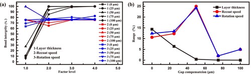
In real-time curing BJAM, the bond breakage and layer shift defects of bonded layers encountered are the two most important factors that decide the success or failure of green part fabricating. (a) presents the within-level means of the bond integrity for each factor. The bond integrity for all gap compensations is lower than 27.52% under the layer thickness of 70 μm, but it rapidly increases to 98.67% with a layer thickness over 150 μm. (b) indicates that gap compensation could significantly impact bond integrity. The influence of layer thickness on bond integrity gradually weakens with an increase in the gap compensation. Both recoat and rotation speeds show a similar variation trend, becoming the dominant influence factor and peaking at 50 μm. In particular, the ranges of recoat speed, rotation speed, and layer thickness are 24.96, 24.17, and 0.44 μm, respectively, under a gap compensation of 50 μm. Furthermore, the effect of layer thickness on bond integrity becomes negligible when the gap compensation exceeds 50 μm, which indicates the importance of gap compensation in powder spreading.
Figure 10. Analysis of bond integrity in orthogonal designed simulations: (a) within-level means; (b) evolution of the within-level range value with different gap compensations.
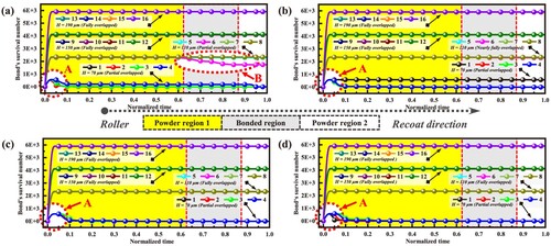
shows the temporal evolution of the survived bond number () over simulation, during which the roller's centre passes sequentially through powder region 1, bonded region, and powder region 2 (regions specified in ). The evolution of survived bond numbers experiences two stages of initial rapidly increasing and remaining at the highest position, indicating that real-time curing occurs and bonded layer is well maintained. As for the breakage, (a – d) shows a sharp bond breakage process occurring in zone A after the bond formation with a normalisation time of 0.05, at which moment the roller is away from the bonded powder area ((a)). Hence, the rapid fracture of the bond in zone A is mainly due to the poor layer strength caused by a thin layer thickness of 70 μm and the initial impact of the powder heap ((a)). Moreover, (a) reveals another slow bond breakage process in zone B while a roller is just above the bonded powder region.
Figure 11. Temporal evolution of bond integrity in orthogonal designed simulations: (a – d) where gap compensation is taken as 25, 50, 75, and 100 μm, respectively.
3.1.3. Layer shift of the bonded layer during powder spreading
Layer shift of the bonded layer is another typical vital defect in real-time curing BJAM. This work represents the layer shift in terms of both position change and attitude change. In detail, displacement components ,
, and
, along the X, Y, and Z axes, respectively, were utilised to quantify the position change of the bonded layer. Moreover, attitude changes components of
,
, and
, corresponding to the yaw, pitch, and roll angles in Tait–Bryan angles representations (Markley and Crassidis Citation2014), respectively, were for the bonded layer's attitude, as shown in (f). These six components were calculated as follows,
(9)
(9) where
is the position vector of the bonded layer's centre of mass at moment t;
,
, and
are the x-component, y-component, and z-component of
;
,
, and
are the x-component, y-component, and z-component of the position vector of the i-th particle in the bonded layer at moment t;
,
,
,
,
, and
are the yaw, pitch, and roll angles of the bonded layer at both moment 0 and t;
and
are the rotation matrices of the rotation angles
and
around the Y and Z axes. Those components of layer shift within items 5–16 are considered and shown in due to the poor bond integrity within items 1–4 ((c)).
Figure 12. Layer shift components in orthogonal designed simulations: (a – e) where gap compensation is taken as 0, 25, 50, 75, and 100 μm, respectively; (f) schematic representation of attitude change components based on Tait – Bryan angles.
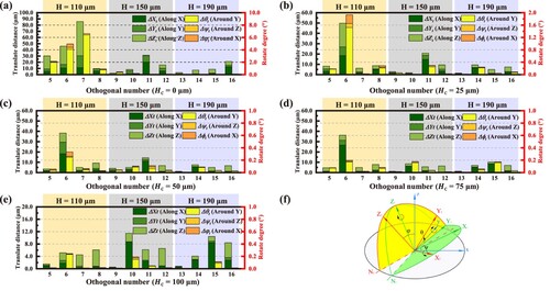
shows that components of and
are the larger two displacement components without a noticeable difference, yet component
is the minor one; component
is the main attitude change component, whereas the components of
and
can be neglected. also presents that a larger component
is always accompanied by a larger component
. As for the layer thickness and gap compensation, the components of
and
greatly reduced with the increase of layer thickness from 110 to 150 μm when gap compensation is lower than 75 μm. While the layer thickness exceeds 150 μm or gap compensation equals 100 μm, the components of
and
have no noticeable difference. This slight difference indicates that the effects of gap compensation and layer thickness on the layer shift become saturated. Moreover, (b – d) shows that the recoat and rotation speeds have an evident influence on component
, and the items within items 5–6 decreased by 82.2%, 90.0%, and 96.5%, respectively.
3.2. Powder spreading mechanisms in real-time curing BJAM
3.2.1. Influence of parameters combination on powder spreading quality
Two more series of one-way designed simulations were conducted around the desirable candidate parameter combinations from Section 3.1. Those two series covering two layer thicknesses of 150 and 110 μm are named series A (preliminary parameters: = 150 μm,
= 75 μm,
= 25 mm/s,
= 80 rad/s) and series B (preliminary parameters:
= 110 μm,
= 75 μm,
= 25 mm/s,
= 40 rad/s). Additionally, only the component
was used to represent layer shift due to the characteristics of synergistic change between those two leading layer shift components of
and
. Note that the bonded integrity of all simulations in both series A and B is basically equal to 100%, indicating a total avoidance of the typical bond breakage () and a good structure of bonded layer; the bond integrity was therefore not displayed. elucidates the evolution of effects from four factors, including recoat speed, rotation speed, gap compensation, and layer number, on packing density and layer shift.
Figure 13. Evolutions of packing density and layer shift for both two series of one-way designed simulations: (a) with recoat speed; (b) with rotation speed; (c) with gap compensation; (d) with different layer numbers.
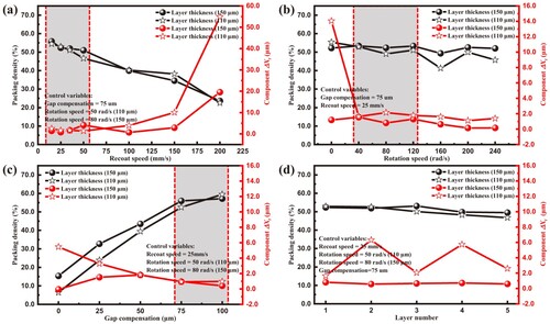
(a) illustrates that the packing density of recoated powder in both series A and B decreases linearly from 66% to 25% while increasing recoat speed from 15 to 200 mm/s. This decreasing trend of packing density indicates the necessity of a low recoat speed (≤100 mm/s). Additionally, the component in series A and B remains unchanged with a lower recoat speed (≤100 mm/s) but increases rapidly with a higher recoat speed (>100 mm/s). Moreover, the component
in series A is larger than that of series B, indicating a thinner layer (110 μm) is more sensitive to the recoat speed. In terms of rotation speed ((b)), the packing density and component
in series A reduces somewhat while increasing rotation speed from 120 to 240 rad/s, demonstrating that rotation speed had little effect on the bonded layer and recoat powder. However, the packing density in series B increases slightly with the reducing rotation speed from 40rad/s to 0rad/s, whereas the component
in series B experiences a surge from 16 to 66 μm. Such results indicate that a moderate rotation speed (40–120 rad/s) is suitable for real-time curing BJAM, resulting in a high-level packing density (55%) and a low-level component
(15 μm).
(c) presented that the packing densities in both series A and B increase linearly with a low gap compensation (≤75 μm) and then experience an increase weaken with a higher gap compensation (75–100 μm). Moreover, the gap compensation in series A has an irregular effect on the component , while a low gap compensation (≤75 μm) in series B has a negative correlation effect on the component
, indicating that increasing a gap compensation can significantly reduce the layer shift of bonded powder. Regarding the layer numbers, (d) shows that the packing density in both series A and B change slightly with an increase in BJAMed layer numbers, whereas the component
in series B differs from that of series A in showing fluctuations. It can be demonstrated that increasing layer number does not lead to an improvement in controlling layer shift; as a result, the initial layer's quality must be carefully handled.
3.2.2. Analysis of microscopic pore size and distribution in the recoated powder
The size and distribution of the microscopic pores of the recoated powder can affect the penetration behaviour of the jetted binder and the propagation behaviour of curing light, although the macroscopic packing density has been analysed in section 3.1.1. The relative volume of pores () based on the Voronoi Tessellation Method (Rycroft Citation2009) was used to characterise the microscopic pore size of the recoated powder within the target region (defined in section 3.1.1) and was calculated by (Yao et al. Citation2021)
(10)
(10) , where
is a volume of Tessellation polyhedron containing a powder particle and
is a volume of the contained powder particle. Additionally, descriptive statistical moments such as mean (
), standard deviation (
), and skewness (
) were employed to describe the pore size distribution; the skewness was calculated as
where
denotes the total number of pores involved, and the
and
are the standard deviation and mean of the pore size, respectively. Figure 14 exhibits the probability density distribution (PDF) of the
for both series A and B.
Clearly, (a) illustrates that all PDFs of the with different recoat speeds exhibit an attribute of positive skew (
> 0); the peaks of those PDFs in both series A and B undergo a significant shift in the direction of bottom right with an increase of recoat speed from 15 to 240 mm/s. I.e. the peaks in series B moved from zone A1 (e.g.:
= 55.8%,
= 1.13,
= 0.52,
= 0.94) to zone B1 (e.g.:
= 23.6%,
= 4.05,
= 2.42,
= 1.75), while the peaks in series A moved from A2 zone (e.g.:
= 54.5%,
= 1.19,
= 0.62,
= 0.94) to zone B2 (e.g.:
= 22.5%,
= 4.28,
= 2.28,
= 1.69). Both zones A1 and A2 have a single peak which indicates unimodal structures of PDFs unlike zones B1 and B2.
Figure 14. Probability density distributions of the pore size for those two series of one-way designed simulations: (a) with recoat speed; (b) with rotation speed; (c) with gap compensation; (d) with different layer numbers.
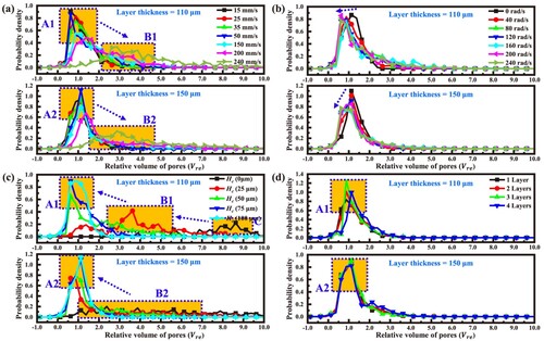
In terms of gap compensation, (c) illustrated that the peak of the PDFs in both series A and B undergo a shift in the direction of up left with the increase of gap compensation from 0 to 100 μm; i.e. the peaks in series B passes through three zones, zone C (e.g.: = 6.4%,
= 17.60,
= 15.56,
= 3.40), zone B1 (e.g.:
= 23.9%,
= 3.99,
= 2.16,
= 1.02), and zone A1 (e.g.:
= 59.4%,
= 1.00,
= 0.40,
= 0.29) sequentially. The peaks in series A passes through two zones of B2 (e.g.:
= 15.4%,
= 6.75,
= 4.77,
= 1.17) and A2 (e.g.:
= 57.2%,
= 1.08,
= 0.42,
= 0.47). Both the zones of A1 and A2 have distinct unimodal structures unlike zones B1, B2, and C.
(b) presents that the peaks of PDFs in series A and B are slightly shifted to the left when increasing a rotation speed from 0 to 240 rad/s. Additionally, the descriptive statistics of the PDFs in series B are ( = 55.4%,
= 1.15,
= 0.45,
= 0.25) and (
= 45.7%,
= 1.60,
= 1.14,
= 1.63), respectively, for the rotation speed of 0 and 240 rad/s; similarly, those in series A are (
= 52.2%,
= 1.28,
= 0.48,
= 0.66) and (
= 52.0%,
= 1.29,
= 0.80,
= 1.65), respectively. Interestingly, the increased rotation speed under a layer thickness of 150 μm has little effect on the packing density and average pore size but increases skewness. This increased skewness indicates a more uneven surface of recoated powder with a more significant fluctuation of the pore size. Moreover, (d) shows that the BJAMed layer numbers have little effect on the PDFs in series A and B.
The above results indicate that gap compensation and recoat speed can significantly change the microscopic pore distribution, unlike rotation speed and layer numbers; increasing the recoat speed to improve efficiency leads to a decrease in packing density but an increase in the average pore size, pore dispersion, and skewness; instead, gap compensation has the opposite effect.
3.2.3. Temporal evolution of layer shift on the bonded powder
Temporal evolution of layer shift with both recoat speed and gap compensation was further analysed to understand the effect mechanisms on layer shift; and only two dominant components of and
were considered (). During the recoat process, the roller's centre passes through powder region 1-1, region 1-2, bonded region, and powder region 2, respectively (regions specified in ); the division between regions 1–1 and 1–2 is merely owing to the surge of layer shift at that normalised time and the ease of describing the surge location. exhibits the temporal evolution of the components of
and
in layer shift of the bonded powder.
Figure 15. Temporal evolution of components of and
in layer shift: (a) with recoat speed (
= 150 μm); (b) with recoat speed (
= 110 μm); (c) with gap compensation (
= 150 μm); (d) with gap compensation (
= 110 μm).
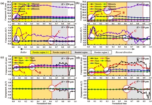
(a) reveals that component in zone A with varying levels of recoat speed under a layer thickness of 150 μm suffered a substantial surge in the initial stage, then stabilised at a normalised time of 0.2, and remained until the end. (b) shows that when a layer thickness is 110 μm, recoat speeds of 150 and 200 mm/s can lead to a growth of component
mainly completed in zone A, while those at other levels of recoat speed mainly occurred in zone B. Moreover, the final component
((b)) with the same parameters is much larger than those under a layer thickness of 150 μm ((a)). Remarkably, (a) shows that only zone A has a surge in component
, while that in zone B remains unchanged. This unchanged trend indicates a well-controlled displacement in zone B achieved via a suitable configuration of layer thickness (150 μm) and a proper recoat speed (< 150 mm/s).
(c – d) suggests that the growth of component in zone B can be well-controlled with an adjusted gap compensation (≥50 μm), but component
in zone A will remain until the end without a correction during the subsequent recoat process. Furthermore, the cause for the growth of component
occurred in zone A is the impact from powder pile determined by the mass of powder pile and recoat speed of roller ((a)).
On the other hand, the growth of components of mainly occurred in zone A and C, respectively. According to (a – d), significant growth of component
in zone A mainly occurs along with a high recoat speed (≥150 mm/s), a low layer thickness (110 μm), or a low gap compensation (0 μm). Furthermore, component
in zone A can experience a surge followed by a rapid decrease to a positive value, while that component in zone C begins a near-sinusoidal single-peaked fluctuation ((b, d)).
3.2.4. Contact force chain insights for layer shift and bond breakage
Analyzing the contact force chain and the total normal force on the bonded layer in DEM can help understand the powder spreading mechanisms in real-time curing BJAM (Chen and Yan Citation2020; Chen et al. Citation2019; Yao et al. Citation2021; Wang et al. Citation2021). presents the normal contact force chain distribution in real-time curing BJAM at four representative moments. The force chain extends from the roller's lower surface along its normal directions through the powder particle medium and finally acts on the bonded layer. Moreover, the force chain propagates in a dendritic pattern, and the strength gradually attenuates from the trunk to the ends. Furthermore, the force chain strength increases as it gets closer to the roller's bottom. (a) depicts that the force chain has a large act depth on the powder within the front side of the bonded layer when the roller moves across the front neighbouring of the bonded area. Instead, (b) presents that when the roller moves over the bonded layer region, the force chain is blocked by the bonded layer, causing a turn to propagate in a horizontal forward direction via the powder upon the bonded layer.
Figure 16. Typical normal contact force chains in the powder spreading under a preliminary parameter and layer shift occurring, respectively: (a) where the roller is located in front of the bonded layer and in the upper region of the bonded layer ( = 150 μm,
= 25 mm/s), respectively; (c-d) where the roller is located in the starting position and in front of the bonded layer (
= 110 μm,
= 200 mm/s), respectively.
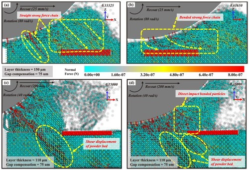
(c, d) shows typical force chain networks with a severe layer shift, corresponding to the layer shift in zones A and B of , respectively. (c) illustrated that the layer shift mechanism in zone A could be that the high-speed roller impacts the initial intact and tightly packed large powder pile to form a dense deep strong force chain that acts on the powder bed below the front of bonded layer, causing a shear displacement of the base powder bed along the recoat direction, and thus carrying the bonded layer to undergo significant layer shift. In zone B, the roller moves to a closer position ahead the bonded layer than in zone A, where the spread powder pile becomes more kinetic and dispersed, and the force chains become decentralised. Major strong force chains still penetrate below the front of the bonded layer, but considerable strong force chains already impact directly on the bonded particles ((d)). The layer shift in zone B can be attributed to both the effects together. And as the roller keeps moving, the force chains directly impacting the bonded particles will increase in proportion and become a major factor, while the shear displacement of the powder bed will recover gradually but not eliminate; additionally, as the recoat speed decreases, the force chains’ action depth will become shallower, and the shear displacement phenomenon will also weaken.
Furthermore, layer shift in zone C is usually smaller than in zones A and B but can accentuate with a small gap compensation ((c, d)). Note that the bonded layer suffered a larger total normal force in zone C ((b)). Therefore, the layer shift mechanism in zone C should differ from that in zones A and B and can thus be ascribed to frictional forces from the compressed media particles and driven by rollers above the bonded particles.
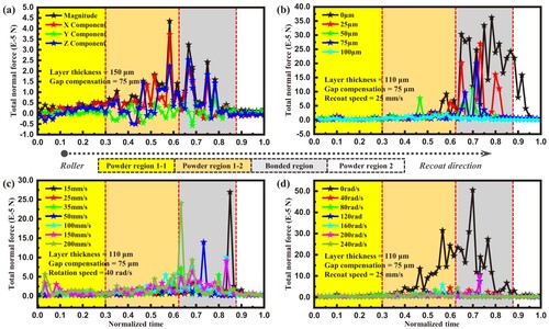
Figure 18. Temporal evolution of the total normal force on the bonded layer: (a) total normal force and its components for a typical powder spreading parameter; (b) total normal force with different gap compensations; (c) total normal force with different recoat speeds; (b) total normal force with different rotation speeds.
A gradual and continuous breakage might occur as the roller passes through the bonded region (Zone B of (a)). In further detail, (a) shows that the bonded layer as the roller passes through the bonded region receives two types of strong force chains: dense vertical downward force chains located directly below the roller, and the dense and short force chains towards the normal line's front formed near the forward point below the roller (unlike the long and bended force chains shown in (b)). The end branches of the latter strong chains disperse from the top centre to the bottom perimeter, acting directly on the adjacent bonded particles. Note here a forward branch is thicker than others, implying a higher normal contact force. Additionally, (c) shows two types of fracture sites: those in the interior along the Y direction and the corners where a more severe breakage has occurred, as presented in (a).
Figure 17. Analysis of the normal contact force chains for bond breakage in real-time curing BJAM ( = 110 μm,
= 110 μm,
= 50 mm/s,
= 0 rad/s): (a) where the roller is located in the upper region of the bond layer; (b-c) a front view and a top view at the end of the powder spreading, respectively.
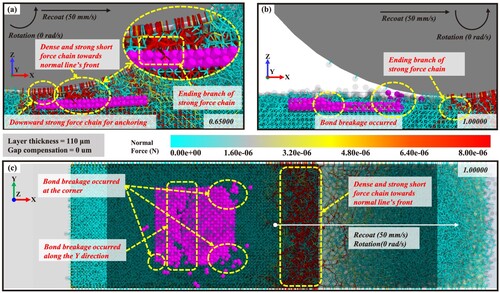
Moreover, it can be further attributed as follows: (i) bond breakage along the Y direction can be caused by the tearing action from the end branch of the dense force chain toward the normal line's front, when the boned layer's left is anchored with the vertical downward force chain directly below the roller; (ii) bond breakage at the corner and margin has a more severe breakage compared to the inner region, which can be attributed to the fact that the particles near the corner or margin of the bonded particles are torn by the strong branching force chains along the X and Y directions; inner particles receive the Y-branching force chains that partially counterbalance each other. This analysis can help determine a powder spreading strategy to avoid potential bond breakage.
3.2.5. Total normal force analysis and powder spreading strategy consideration
presents the temporal evolutions of the total normal force on the bonded layer under different conditions. (a) shows that the X-component of normal force on the bonded layer in powder region 1–2 is higher than that in the bonded region. Interestingly, the growth of translational component in layer shift occurs mainly in zones A and B (), suggesting that regulating layer shift in zones A and B is more urgent. Furthermore, the displacement surge of the component
under low recoat speed (<150 mm/s) occurs largely in zone B, while the layer shift surge under high recoat speed (≥150 mm/s) occurs mainly in zone A. (b) illustrates that the total normal force on the bonded layer is higher when the roller passes through it than in the other regions, and it increases significantly with decreasing a gap compensation. This increase implies that the medium particles exert a stronger external force on the bonded particles. Furthermore, increased recoat speed has a negligible effect on the total normal force of the bonded layer ((c)) but leads to a linear decrease in packing density ((a)). As a result, recoat speed should be controlled at a lower level, contrary to efficiency.
For a low-level recoat speed (≤50 mm/s), the growth of component in zone A is insignificant, while that in zone B is dominant; therefore, controlling the growth of component
in zone B is the most crucial task. Regarding the powder spreading parameters, the last section shows that the growth of the displacement component
in zone B can be controlled at a low level via increasing the layer thickness ((a – b)) and can be further reduced by optimising the gap compensation ((c)). The synergistic effect of layer thickness and gap compensation can be explained by EquationEq. (7)
(7)
(7) . Increasing the layer thickness and gap compensation ultimately raises the gap height, resulting in lifting the position of the force chain with a certain depth of interaction (). Moreover, the lower end of the force chain is more attenuated than the upper trunk, thus lifting the force chain and resultantly leading to less force to the media of unbonded powder and bonded layer. Finally, the layer shift and breakage of the bonded layers are suppressed simultaneously by avoiding the strong force chain endings.
The attitude change in zone A can be well-controlled by setting a gap compensation of 25 μm or more ((c)). In contrast, the attitude change in zone C occurs only with a low gap compensation of 0 μm and experiences a near-sinusoidal single-peaked fluctuation as the roller passes through the bonded powder ((d)). This fluctuation can be explained by the torque generated from the Z-component of the normal force around the centre of mass of the bonded layer.
clearly reveals that a non-rotating roller causes a sharp increase in the total normal force on the bonded layer due to the static friction between the media powder particles. However, a low and necessary rotation speed (> 40 rad/s) leads to a significantly reduced force on the bonded layer, which is beneficial to ensuring bond integrity and controlling layer shift. This significant difference suggests the necessity of a rotation movement of a roller recoater for real-time curing BJAM. As for the characteristics of velocity distribution of the powder particle within the powder pile, a low and necessary speed (> 40 rad/s) can lead to the maximum velocity of powder particles adjacent to a roller within the powder pile, indicating a sufficient flowability within the powder pile ((b – d)). Comparatively, a blade can lead to the lowest velocity of powder particles nearest to the blade recoater and present a classic ‘force arch’ phenomenon (Chen et al. Citation2019; Yao et al. Citation2021), which has been widely employed as the recoater in powder bed fusion AM processes (Wang et al. Citation2021). This difference can be ascribed to a rotating roller continually exerting tangential forces on the powder particles in contact, accelerating them to the maximum speed ((b – d)), thus avoiding the stable force chain structure produced with a non-rotating roller.
A powder feeding method that is prone to layer shift and bond breakage results in a narrow process window and should be adjusted in engineering. The layer shift and bond breakage can be caused by the dense and strong force chains, according to the previous attribution analysis. The falling impact of a large powder pile (shown in (a) and (c)) may cause bonded layer's attitude fluctuation (zone A in (b)). (a) indicates that an initial powder pile isn't fully spread out by zone A's normalised time; the powder pile at this moment is taller than the one afterwards, implying a bigger gravitational potential. Combined with the fact that the particles are not fully dynamic, the powder pile has a denser packing structure, resulting in a denser distribution of strong force chains ((c)). The piston feeding method supplies all the powder required to cover a layer thickness onto the powder bed at once before spreading the powder. A piston-feeding BJAM machine that can manufacture green parts with a larger cross-sectional area (larger build volume) will thus have a larger and taller powder pile, which means that the powder near the roller will be more compact due to the powder pile's gravity and the resistance of more powder needed to recoat. Additionally, the particles at the top of the higher powder pile have a stronger gravitational potential, which may cause attitude fluctuations when pushed by the roller. Given these considerations, piston feeding may be less suitable as a supply technique for building large cross-section parts by BJAM, while hoper feeding is more suitable to avoid potential defects by dropping a moderate amount of powder while spreading it.
4. Conclusions
This work established a numerical model considering local cross-links to depict the bonded powder particle behaviour for real-time curing BJAM based on the DEM with Hertz-Mindlin with JKR cohesion and PBM. The effects of BJAM parameters containing layer thickness, gap compensation, recoat speed, rotation speed, and layer number on powder spreading are revealed. In addition to the packing density and pore size PDF for the recoated powder, both bond integrity and layer shift are comprehensively quantified to characterise the structural integrity and accuracy of the real-time curing bonded layer. The primary conclusions are as follows:
The packing density and the pore size PDF are mainly affected by layer thickness, gap compensation, and recoat speed but are not sensitive to rotation speed. A higher packing density leads to a lower positive skewness of the pore size PDF, indicating a better flatness of recoated powder. A lower recoat speed leads to a higher packing density, contradicting a higher efficiency.
Layer shift should be a critical problem; bond integrity is more easily controlled than layer shift and may occur when the roller passes over the bonded layer. The growth of translational component
mainly occurs when the roller is located in front of the bonded layer rather than directly above the bonded layer. The growth of the attitude component
Increasing the layer thickness and gap compensation can synergistically suppress the layer shift and breakage of the bonded layers to obtain a fine-structure bonded layer; however, an excessive layer thickness or gap compensation can lead to poor accuracy of the green part. A lower and necessary rotation speed (>40 rad/s) can break the stable force chain structure in the powder pile, significantly reducing the layer shift and ensuring the bond integrity.
Irreversible surges of components of
The force chain extends from the roller through the powder particle medium and acts on the bonded layer finally, propagating in a dendritic pattern along the roller's surface normal direction with a gradual weakening in strength from the trunk to the ends. Additionally, when the roller is directly above the bonded layer, the bonded layer can interrupt the force chain and cause a horizontal forward turn of the force chain's propagation direction.
This research has theoretical guiding significance for designing appropriate powder spreading strategies and parameters to ensure the quality of green parts in real-time curing BJAM. Meanwhile, it also has a reference significance for the mixed-curing BJAM, even the other powder bed-based additive manufacturing techniques without support structures. This study simplifies the actual spreading process, such as the initial powder bed created programmatically with FCC sphere packing may lead to the weakening results of the layer shift. Other factors such as warpage, powder particle size distribution, and roller condition also affect the powder spreading, which requires further research, especially warpage.
Acknowledgments
The authors acknowledge Dr. Fenbin Wang and Zhuhai Tianwei New Material Co. LTD for their support on the photosensitive binder utilised in real-time curing BJAM.
Disclosure statement
No potential conflict of interest was reported by the author(s).
Additional information
Funding
Notes on contributors
Shibiao Wu
Shibiao Wu is a PhD candidate at the School of Mechanical and Automotive Engineering, South China University of Technology, China. His research interests are the forming process, numerical simulation, and control system of binder jetting additive manufacturing technology.
Yongqiang Yang
Yongqiang Yang is a Professor at the School of Mechanical and Automotive Engineering, South China University of Technology, China. His main research interests are metal additive manufacturing technology, including laser powder bed fusion additive manufacturing technology and binder jetting additive manufacturing technology.
Yanlu Huang
Yanlu Huang is an Associate Professor at the School of Mechanical and Automotive Engineering, South China University of Technology, China. His main research interest is the numerical simulation of processes in metal additive manufacturing.
Changjun Han
Changjun Han is an Assistant Professor at the School of Mechanical and Automotive Engineering, South China University of Technology, China. His research interest focuses on additive manufacturing of metals.
Jie Chen
Jie Chen received his PhD from the School of Mechanical and Automotive Engineering, South China University of Technology, and is currently working at the Institute of Intelligent Manufacturing, Guangdong Academy of Sciences, China. His research interest is the multi-metal-material structures fabricated with powder bed fusion additive manufacturing.
Yunmian Xiao
Yunmian Xiao is a PhD candidate at the School of Mechanical and Automotive Engineering, South China University of Technology, China. His research interest is the multi-metal-material structures fabricated with powder bed fusion additive manufacturing.
Yang Li
Yang Li is a lecturer at the School of Mechanical and Automotive Engineering, South China University of Technology, China. His has worked on projects for the development of control systems of additive manufacturing and power control systems in welding.
Di Wang
Di Wang is a Professor at the School of Mechanical and Automotive Engineering, South China University of Technology, China. He has worked on projects for metal additive manufacturing in equipment/software, design method, process optimization, process monitoring, and application.
References
- Cao, Shu, Yang Qiu, XingFang Wei, and HongHai Zhang. 2015. “Experimental and Theoretical Investigation on Ultra-Thin Powder Layering in Three Dimensional Printing (3DP) by a Novel Double-Smoothing Mechanism.” Journal of Materials Processing Technology 220: 231–242. doi:10.1016/j.jmatprotec.2015.01.016.
- Chen, Hui, Yuxiang Chen, Ying Liu, Qingsong Wei, Yusheng Shi, and Wentao Yan. 2020. “Packing Quality of Powder Layer During Counter-Rolling-Type Powder Spreading Process in Additive Manufacturing.” International Journal of Machine Tools and Manufacture 153: 103553. doi:10.1016/j.ijmachtools.2020.103553.
- Chen, Hui, Qingsong Wei, Yingjie Zhang, Fan Chen, Yusheng Shi, and Wentao Yan. 2019a. “Powder-spreading Mechanisms in Powder-Bed-Based Additive Manufacturing: Experiments and Computational Modeling.” Acta Materialia 179: 158–171. doi:10.1016/j.actamat.2019.08.030.
- Chen, Hui, and Wentao Yan. 2020. “Spattering and Denudation in Laser Powder Bed Fusion Process: Multiphase Flow Modelling.” Acta Materialia 196: 154–167. doi:10.1016/j.actamat.2020.06.033.
- Chen, Jie, Yongqiang Yang, Changhui Song, Mingkang Zhang, and S. Di Wang Wu. 2019b. “Interfacial Microstructure and Mechanical Properties of 316L/CuSn10 Multi-Material Bimetallic Structure Fabricated by Selective Laser Melting.” Materials Science and Engineering: A 752: 75–85. doi:10.1016/j.msea.2019.02.097.
- Chen, Sheng, Shuiqing Li, and Mengmeng Yang. 2015. “Sticking/Rebound Criterion for Collisions of Small Adhesive Particles: Effects of Impact Parameter and Particle Size.” Powder Technology 274: 431–440. doi:10.1016/j.powtec.2015.01.051.
- Clares, Ana Paula, and Guha Manogharan. 2021. “Discrete-Element Simulation of Powder Spreading Process in Binder Jetting, and the Effects of Powder Size.” Paper presented at the international manufacturing science and engineering conference.
- Cramer, Corson L., Natalie R. Wieber, Trevor G. Aguirre, Richard A. Lowden, and Amy M. Elliott. 2019. “Shape Retention and Infiltration Height in Complex WC-Co Parts Made via Binder jet of WC with Subsequent Co Melt Infiltration.” Additive Manufacturing 29: 100828. doi:10.1016/j.addma.2019.100828.
- Deng, Hongxin, Yanlu Huang, Shibiao Wu, and Yongqiang Yang. 2022. “Binder Jetting Additive Manufacturing: Three-Dimensional Simulation of Micro-Meter Droplet Impact and Penetration Into Powder Bed.” Journal of Manufacturing Processes 74: 365–373. doi:10.1016/j.jmapro.2021.12.019.
- Desai, P., and C. Iii. 2021. “A Dem Model to Predict and Correct Spreader Shear-Induced Part Deformation in Binder Jet Additive Manufacturing.” 14th WCCM-ECCOMAS congress.
- Escano, L. I., N. D. Parab, L. Xiong, Q. Guo, C. Zhao, K. Fezzaa, W. Everhart, T. Sun, and L. Chen. 2018. “Revealing Particle-Scale Powder Spreading Dynamics in Powder-Bed-Based Additive Manufacturing Process by High-Speed x-ray Imaging.” Scientific Reports 8 (1): 15079. doi:10.1038/s41598-018-33376-0.
- Escano, Luis I., Niranjan D. Parab, Lianghua Xiong, Qilin Guo, Cang Zhao, Tao Sun, and Lianyi Chen. 2019. “Investigating Powder Spreading Dynamics in Additive Manufacturing Processes by In-Situ High-Speed X-ray Imaging.” Synchrotron Radiation News 32 (2): 9–13. doi:10.1080/08940886.2019.1582281.
- Fouda, Yahia M., and Andrew E. Bayly. 2019. “A DEM Study of Powder Spreading in Additive Layer Manufacturing.” Granular Matter 22 (1): 1–15. doi:10.1007/s10035-019-0971-x.
- Fuchs, Sebastian L, Patrick M Praegla, Christian J Cyron, Wolfgang A Wall, and Christoph Meier. 2022. “A Versatile SPH Modeling Framework for Coupled Microfluid-Powder Dynamics in Additive Manufacturing: Binder Jetting, Material Jetting, Directed Energy Deposition and Powder Bed Fusion.” arXiv Preprint ArXiv:2201.01677, doi:10.48550/arXiv.2201.01677.
- Gilmer, Dustin, Lu Han, Eunice Hong, Derek Siddel, Alexander Kisliuk, Shiwang Cheng, Dan Brunermer, Amy Elliott, and Tomonori Saito. 2020. “An in-Situ Crosslinking Binder for Binder Jet Additive Manufacturing.” Additive Manufacturing 35: 101341. doi:10.1016/j.addma.2020.101341.
- Hærvig, J., U. Kleinhans, C. Wieland, H. Spliethoff, A. L. Jensen, K. Sørensen, and T. J. Condra. 2017. “On the Adhesive JKR Contact and Rolling Models for Reduced Particle Stiffness Discrete Element Simulations.” Powder Technology 319: 472–482. doi:10.1016/j.powtec.2017.07.006.
- Hanley, Kevin J., Catherine O’Sullivan, Jorge C. Oliveira, Kevin Cronin, and Edmond P. Byrne. 2011. “Application of Taguchi Methods to DEM Calibration of Bonded Agglomerates.” Powder Technology 210 (3): 230–240. doi:10.1016/j.powtec.2011.03.023.
- Johnson, Kenneth Langstreth, Kevin Kendall, and A. D. Roberts. 1971. “Surface Energy and the Contact of Elastic Solids.” Proceedings of the Royal Society of London. A. Mathematical and Physical Sciences 324 (1558): 301–313. doi:10.1098/rspa.1971.0141.
- Landis, Markley F, and John L Crassidis. 2014. “Euler Angles.” In Fundamentals of Spacecraft Attitude Determination and Control, edited by James, R. Wertz, 361–364. New York: Springer.
- Lee, Y. S., P. Nandwana, and W. Zhang. 2018. “Dynamic Simulation of Powder Packing Structure for Powder Bed Additive Manufacturing.” The International Journal of Advanced Manufacturing Technology 96 (1-4): 1507–1520. doi:10.1007/s00170-018-1697-3.
- Lee, Yousub, Peeyush Nandwana, and Srdjan Simunovic. 2021. “Powder Spreading, Densification, and Part Deformation in Binder Jetting Additive Manufacturing.” Progress in Additive Manufacturing 7 (1): 111–125. doi:10.1007/s40964-021-00214-1.
- Li, Yang, Wenbin Kan, Yanming Zhang, Mingzhi Li, Xiaoyu Liang, Yefeng Yu, and Feng Lin. 2021. “Microstructure, Mechanical Properties and Strengthening Mechanisms of IN738LC Alloy Produced by Electron Beam Selective Melting.” Additive Manufacturing 47: 102371. doi:10.1016/j.addma.2021.102371.
- Liravi, Farzad, and Mihaela Vlasea. 2018. “Powder Bed Binder Jetting Additive Manufacturing of Silicone Structures.” Additive Manufacturing 21: 112–124. doi:10.1016/j.addma.2018.02.017.
- Lv, Xinyuan, Fang Ye, Laifei Cheng, Shangwu Fan, and Yongsheng Liu. 2019. “Binder Jetting of Ceramics: Powders, Binders, Printing Parameters, Equipment, and Post-Treatment.” Ceramics International 45 (10): 12609–12624. doi:10.1016/j.ceramint.2019.04.012.
- Ma, Chao, Zhijian Pei, Alaa Elwany, Wenchao Du, and Ming Li. 2020. “Metal Binder Jetting Additive Manufacturing: A Literature Review.” Journal of Manufacturing Science and Engineering 142 (9): 090801. doi:10.1115/1.4047430.
- Mamun, Abdullah Al, Chenang Liu, Chen Kan, and Wenmeng Tian. 2022. “Securing Cyber-Physical Additive Manufacturing Systems by in-Situ Process Authentication Using Streamline Video Analysis.” Journal of Manufacturing Systems 62: 429–440. doi:10.1016/j.jmsy.2021.12.007.
- Manotham, Supalak, Somruethai Channasanon, Phornwalan Nanthananon, Siriporn Tanodekaew, and Passakorn Tesavibul. 2021. “Photosensitive Binder Jetting Technique for the Fabrication of Alumina Ceramic.” Journal of Manufacturing Processes 62: 313–322. doi:10.1016/j.jmapro.2020.12.011.
- Manotham, Supalak, and Passakorn Tesavibul. 2022. “Effect of Particle Size on Mechanical Properties of Alumina Ceramic Processed by Photosensitive Binder Jetting with Powder Spattering Technique.” Journal of the European Ceramic Society 42 (4): 1608–1617. doi:10.1016/j.jeurceramsoc.2021.11.062.
- Mao, Yiwei, Jingwen Li, Wei Li, Daosheng Cai, and Qingsong Wei. 2021. “Binder Jetting Additive Manufacturing of 316L Stainless-Steel Green Parts with High Strength and Low Binder Content: Binder Preparation and Process Optimization.” Journal of Materials Processing Technology 291: 117020. doi:10.1016/j.jmatprotec.2020.117020.
- Mariani, Marco, Ruben Beltrami, Paolo Brusa, Carmen Galassi, Raffaele Ardito, and Nora Lecis. 2021. “3D Printing of Fine Alumina Powders by Binder Jetting.” Journal of the European Ceramic Society 41 (10): 5307–5315. doi:10.1016/j.jeurceramsoc.2021.04.006.
- Martin, Etienne, Arunkumar Natarajan, Srikanth Kottilingam, and Rasim Batmaz. 2021. “Binder Jetting of “Hard-to-Weld” High Gamma Prime Nickel-Based Superalloy RENÉ 108.” Additive Manufacturing 39: 101894. doi:10.1016/j.addma.2021.101894.
- Maximenko, A. L., I. D. Olumor, A. P. Maidaniuk, and E. A. Olevsky. 2021. “Modeling of Effect of Powder Spreading on Green Body Dimensional Accuracy in Additive Manufacturing by Binder Jetting.” Powder Technology 385: 60–68. doi:10.1016/j.powtec.2021.02.070.
- Meier, Christoph, Reimar Weissbach, Johannes Weinberg, Wolfgang A. Wall, and A. John Hart. 2019. “Critical Influences of Particle Size and Adhesion on the Powder Layer Uniformity in Metal Additive Manufacturing.” Journal of Materials Processing Technology 266: 484–501. doi:10.1016/j.jmatprotec.2018.10.037.
- Miao, Guanxiong, Wenchao Du, Mohammadamin Moghadasi, Zhijian Pei, and Chao Ma. 2020. “Ceramic Binder Jetting Additive Manufacturing: Effects of Granulation on Properties of Feedstock Powder and Printed and Sintered Parts.” Additive Manufacturing 36: 101542. doi:10.1016/j.addma.2020.101542.
- Mostafaei, Amir, Amy M. Elliott, John E. Barnes, Fangzhou Li, Wenda Tan, Corson L. Cramer, Peeyush Nandwana, and Markus Chmielus. 2021. “Binder jet 3D Printing—Process Parameters, Materials, Properties, Modeling, and Challenges.” Progress in Materials Science 119: 100707. doi:10.1016/j.pmatsci.2020.100707.
- Mussatto, Andre, Robert Groarke, Aidan O’Neill, Muhannad Ahmed Obeidi, Yan Delaure, and Dermot Brabazon. 2021. “Influences of Powder Morphology and Spreading Parameters on the Powder Bed Topography Uniformity in Powder Bed Fusion Metal Additive Manufacturing.” Additive Manufacturing 38: 101807. doi:10.1016/j.addma.2020.101807.
- Nandwana, Peeyush, Rangasayee Kannan, and Derek Siddel. 2020. “Microstructure Evolution During Binder jet Additive Manufacturing of H13 Tool Steel.” Additive Manufacturing 36: 101534. doi:10.1016/j.addma.2020.101534.
- Nanthananon, Phornwalan, Siriporn Tanodekaew, Passakorn Tesavibul, Supalak Manotham, Pakkanun Kaewkong, and Somruethai Channasanon. 2021. “Enhancing the Mechanical Properties of Photosensitive Binder Jetting PLA via Dual Curing and Thermal Treatment.” Journal of Applied Polymer Science 139 (15): 51942. doi:10.1002/app.51942.
- Oropeza, D., R. Roberts, and A. J. Hart. 2021. “A Modular Testbed for Mechanized Spreading of Powder Layers for Additive Manufacturing.” Review of Scientific Instruments 92 (1): 015114. doi:10.1063/5.0031191.
- Oropeza Gomez, Daniel. 2021. “Testbeds for Advancement of Powder Bed Additive Manufacturing with Application to Reactive Binder Jetting of Ceramics.” Massachusetts Institute of Technology.
- O’Sullivan, Catherine, and Jonathan D. Bray. 2004. “Selecting a Suitable Time Step for Discrete Element Simulations That use the Central Difference Time Integration Scheme.” Engineering Computations 21 (2/3/4): 278–303. doi:10.1108/02644400410519794.
- Penny, Ryan W., Patrick M. Praegla, Marvin Ochsenius, Daniel Oropeza, Reimar Weissbach, Christoph Meier, Wolfgang A. Wall, and A. John Hart. 2021. “Spatial Mapping of Powder Layer Density for Metal Additive Manufacturing via Transmission X-ray Imaging.” Additive Manufacturing 46: 102197. doi:10.1016/j.addma.2021.102197.
- Phua, Arden, Christian Doblin, Phil Owen, Chris H. J. Davies, and Gary W. Delaney. 2021. “The Effect of Recoater Geometry and Speed on Granular Convection and Size Segregation in Powder Bed Fusion.” Powder Technology 394: 632–644. doi:10.1016/j.powtec.2021.08.058.
- Potyondy, D. O., and P. A. Cundall. 2004. “A Bonded-Particle Model for Rock.” International Journal of Rock Mechanics and Mining Sciences 41 (8): 1329–1364. doi:10.1016/j.ijrmms.2004.09.011.
- Qu, Tongming, Y. T. Feng, Min Wang, and Shengqiang Jiang. 2020. “Calibration of Parallel Bond Parameters in Bonded Particle Models via Physics-Informed Adaptive Moment Optimisation.” Powder Technology 366: 527–536. doi:10.1016/j.powtec.2020.02.077.
- Rodríguez-González, P., A. I. Fernández-Abia, M. A. Castro-Sastre, and J. Barreiro. 2020. “Heat Treatments for Improved Quality Binder Jetted Molds for Casting Aluminum Alloys.” Additive Manufacturing 36: 101524. doi:10.1016/j.addma.2020.101524.
- Rosala, Fabrice. 2021. “Improvement and Development of Powder Spreadability Testing.” Thesis. KTH Royal Institute of Technology, Stockholm (Sweden).
- Rycroft, Chris. 2009. “Voro++: A Three-Dimensional Voronoi Cell Library in C++.” Chaos 19: 041111. doi:10.1063/1.3215722.
- Sachs, Emanuel M, John S Haggerty, Michael J Cima, and Paul A Williams. 1994. “Three-dimensional printing techniques.” In.: Google Patents.
- Schmutzler, Christoph, Tobias H. Stiehl, and Michael F. Zaeh. 2019. “Empirical Process Model for Shrinkage-Induced Warpage in 3D Printing.” Rapid Prototyping Journal 25 (4): 721–727. doi:10.1108/rpj-04-2018-0098.
- Schöpfer, Martin P. J., Steffen Abe, Conrad Childs, and John J. Walsh. 2009. “The Impact of Porosity and Crack Density on the Elasticity, Strength and Friction of Cohesive Granular Materials: Insights from DEM Modelling.” International Journal of Rock Mechanics and Mining Sciences 46 (2): 250–261. doi:10.1016/j.ijrmms.2008.03.009.
- Sheydaeian, Esmat, Kaveh Sarikhani, Pu Chen, and Ehsan Toyserkani. 2017. “Material Process Development for the Fabrication of Heterogeneous Titanium Structures with Selective Pore Morphology by a Hybrid Additive Manufacturing Process.” Materials & Design 135: 142–150. doi:10.1016/j.matdes.2017.09.025.
- Sivarupan, Tharmalingam, Nagasivamuni Balasubramani, Prateek Saxena, Devarajan Nagarajan, Mohamed El Mansori, Konstantinos Salonitis, Mark Jolly, and Matthew S. Dargusch. 2021. “A Review on the Progress and Challenges of Binder jet 3D Printing of Sand Moulds for Advanced Casting.” Additive Manufacturing 40: 101889. doi:10.1016/j.addma.2021.101889.
- Stevens, Erica, Katerina Kimes, Daniel Salazar, Amir Mostafaei, Rafael Rodriguez, Aaron Acierno, Patricia Lázpita, Volodymyr Chernenko, and Markus Chmielus. 2021. “Mastering a 1.2 K Hysteresis for Martensitic Para-Ferromagnetic Partial Transformation in Ni-Mn(Cu)-Ga Magnetocaloric Material via Binder jet 3D Printing.” Additive Manufacturing 37: 101560. doi:10.1016/j.addma.2020.101560.
- Tamás, Kornél, Ádám Kovács, and István J. Jóri. 2016. “The Evaluation of the Parallel Bond’s Properties in DEM Modeling of Soils.” Periodica Polytechnica Mechanical Engineering 60 (1): 21–31. doi:10.3311/PPme.8427.
- Tan, Yuanqiang, Jiangtao Zhang, Xiang Li, Yangli Xu, and Chuan-Yu Wu. 2021. “Comprehensive Evaluation of Powder Flowability for Additive Manufacturing Using Principal Component Analysis.” Powder Technology 393: 154–164. doi:10.1016/j.powtec.2021.07.069.
- Wang, Lin, Aibing Yu, Erlei Li, Haopeng Shen, and Zongyan Zhou. 2021. “Effects of Spreader Geometry on Powder Spreading Process in Powder Bed Additive Manufacturing.” Powder Technology 384: 211–222. doi:10.1016/j.powtec.2021.02.022.
- Weber, Sebastian, Joaquin Montero, Matthias Bleckmann, and Kristin Paetzold. 2021. “Support-Free Metal Additive Manufacturing: A Structured Review on the State of the Art in Academia and Industry.” Proceedings of the Design Society 1: 2811–2820. doi:10.1017/pds.2021.542.
- Wilts, Emily M., and Timothy E. Long. 2020. “Sustainable Additive Manufacturing: Predicting Binder Jettability of Water-Soluble: Biodegradable and Recyclable Polymers.” Polymer International 70 (7): 958–963. doi:10.1002/pi.6108.
- Xu, Zhengkai, Zhiguang Zhu, Pan Wang, Ganesh Kumar Meenashisundaram, Sharon Mui Ling Nai, and Jun Wei. 2020. “Fabrication of Porous CoCrFeMnNi High Entropy Alloy Using Binder Jetting Additive Manufacturing.” Additive Manufacturing 35: 101441. doi:10.1016/j.addma.2020.101441.
- Yao, Dengzhi, Xizhong An, Haitao Fu, Hao Zhang, Xiaohong Yang, Qingchuan Zou, and Kejun Dong. 2021. “Dynamic Investigation on the Powder Spreading During Selective Laser Melting Additive Manufacturing.” Additive Manufacturing 37: 101707. doi:10.1016/j.addma.2020.101707.
- Zhou, Zuoxin, Alex Lennon, Fraser Buchanan, Helen O. McCarthy, and Nicholas Dunne. 2020. “Binder Jetting Additive Manufacturing of Hydroxyapatite Powders: Effects of Adhesives on Geometrical Accuracy and Green Compressive Strength.” Additive Manufacturing 36: 101645. doi:10.1016/j.addma.2020.101645.
- Ziaee, Mohsen, and Nathan B. Crane. 2019. “Binder Jetting: A Review of Process: Materials, and Methods.” Additive Manufacturing 28: 781–801. doi:10.1016/j.addma.2019.05.031.