
 ?Mathematical formulae have been encoded as MathML and are displayed in this HTML version using MathJax in order to improve their display. Uncheck the box to turn MathJax off. This feature requires Javascript. Click on a formula to zoom.
ABSTRACT
Additive manufacturing (AM) is a key enabler and technological pillar of the fourth industrial revolution (Industry 4.0) as it increases productivity and improves resource efficiency. However, current AM systems present some limitations in terms of fabrication time, versatility, and efficiency. The concept of teams of robots represents a novel approach for AM aiming to address these limitations. This review paper discusses the current state-of-the-art of the use of cooperative AM systems based on gantry systems, robotic arms, and mobile robots. The information flow, path planning and slicing strategies are discussed in detail, and several examples of the use of cooperative AM systems are provided. Finally, major research challenges and future perspectives are discussed.
1. Introduction
Additive manufacturing (AM) is a group of processes that create 3D parts by adding material, usually in a layer-by-layer fashion (DebRoy et al. Citation2018). Due to material limitations, AM was initially used to create parts to support design activities, function testing, and relief models for geographical applications (Bártolo and Gibson Citation2011). In the 1990s, AM was significantly used for the direct fabrication of tools (e.g. thermoforming and sand casting moulds) (Kruth, Leu, and Nakagawa Citation1998; Hodder and Chalaturnyk Citation2019; Czelusniak et al. Citation2018). It was also used for the fabrication of masters for further production of tools using different techniques such as vacuum casting, epoxy, and spray tooling (Boparai, Singh, and Singh Citation2016). Significant developments on high-performance materials for AM and the improvement of fabrication accuracy and control enabled AM to progress into a rapid manufacturing process, allowing to produce functional parts (Ngo et al. Citation2018). Currently, AM is used to create nano- to macro-scale parts in a wide range of materials for multiple fields such as consumer goods, aerospace, defense, aeronautics, construction, medical and tissue engineering (Salles and Gyi Citation2013; Leal et al. Citation2017; Uriondo, Esperon-Miguez, and Perinpanayagam Citation2015; Bos et al. Citation2016; Aydin and Kucuk Citation2018; Liu et al. Citation2021; Meng, He, and Li Citation2021). Recent trends focus on the use of AM to create functionally graded structures and smart structures (e.g. using shape memory or self-healing materials) and the combination of AM with other techniques through the development of hybrid or multi-modal fabrication systems (Roach et al. Citation2019; Craveiro et al. Citation2020).
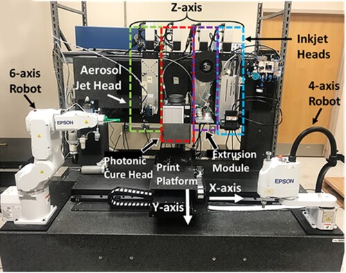
According to the American Society for Testing and Materials (ASTM), AM comprises seven different technologies (ASTM Citation2015): material extrusion, vat photopolymerisation, sheet lamination, powder bed fusion, directed energy deposition, material and binder jetting (). Depending on the mechanical system used to control the printing bed/printheads, AM comprises gantry robots, robotic arms, and mobile robots which represents an emerging area in the field of AM (Bhatt et al. Citation2020; Tay et al. Citation2017). As observed from , the majority of AM systems are based on the original concept of gantry platforms, due to the high precision of positioning the end-effector, and simplicity of their joints structure and control system (Siciliano et al. Citation2009). However, gantry systems present a limited workspace and a limited ratio between the workspace and the volume occupied by the machine (Tyapin et al. Citation2007).
Table 1. AM technologies and corresponding implementation using different robotic systems (E – explored; NE – Not-explored).
Recently, a large number of AM systems based on robotic arms have been proposed (Bin Ishak, Fisher, and Larochelle Citation2016; Stevens et al. Citation2016; Bhatt et al. Citation2019b; Ding et al. Citation2015; Badarinath and Prabhu Citation2021). These systems were developed for applications requiring high workspaces and dexterous systems, allowing multi-axis printing by using joint configurations with high degrees of freedom (Urhal et al. Citation2019). For example, Dai et al. (Citation2018) used multi-axis printing robotic arms to eliminate the need for support structures on complex objects, which is impossible to achieve using conventional gantry AM machines. However, the design and control of robotic arms are more complex. Additionally, the singularities of the robotic arm within the printing space must be considered (Yu and Luo Citation2018). Moreover, due to structural flexibilities, vibrations are noticeable, affecting the printing quality and accuracy (Farahbakhsh et al. Citation2022).
An emerging trend in AM is the use of mobile robots (ground or aerial) enabling the printing process tobe performed on large workspaces. The portability of mobile robots allows AM to be used in places that are dangerous or difficult to be reached by humans. However, these systems present some limitations in terms of precision of positioning the printhead (e.g. uncertainties in localisation (Tiryaki, Zhang, and Pham Citation2020), and aerial robots’ fast rotating propellers may affect the printing process (Hunt et al. Citation2014; Zhang et al. Citation2022)). Moreover, some configurations of mobile robots are more susceptible to vibrations than others, for example, the discrete number of rollers in mecanum wheeled robots is a large source of vibrations (Xie et al. Citation2015).
The teams of robots concept consists on the use of multiple robots intending to perform collective tasks, and can be classified as homogeneous or heterogeneous systems (Yan, Jouandeau, and Cherif Citation2013). In homogeneous systems, all robots share the same capabilities (Jiang et al. Citation2020b). In the context of this review, homogeneous systems correspond to cooperative printing robots working together on the printing process of the same part. Heterogeneous systems correspond to assistive robots that perform different supportive tasks such as pick-and-place to assist the robot responsible for the printing process (Roach et al. Citation2019).
Systems with multiple cooperative robots introduce several advantages such as task complexity reduction, increase performance, enhanced reliability, and system design simplicity. A task that is complex for one robot, due to the nature of the task or the intrinsic characteristics of the robot, can be shared between multiple robots in the system (Khamis, Hussein, and Elmogy Citation2015). Moreover, sharing a task between multiple robots helps in increasing performance and reducing the total time required to finish the task (Shen, Pan, and Qian Citation2019). Reliability is also an advantage for cooperative robots, as if a robot fails for any reason other robots in the system can replace it without affecting the completion of the task (Stancliff, Dolan, and Trebi-Ollennu Citation2009; Reig et al. Citation2021). Finally, designing multiple smaller robots is easier and more flexible than designing a single large system that must have the capabilities of all the other robots (Khamis, Hussein, and Elmogy Citation2015).
Teams of robots are used in traditional manufacturing (Huang and Lin Citation2003; Zhao et al. Citation2020, Citation2021), where multiple robots work cooperatively to achieve manufacturing tasks that are time-consuming, inefficient, or impossible to be performed by a single robot. Similarly, the use of a team of cooperative robots has the potential to significantly transform AM, allowing to create or repair large complex multi-material parts in a wide range of environments (in-site or off-site), improving versatility, productivity, and efficiency. The types of robots discussed in this paper are gantry systems, robotic arms, and land mobile robots. Aerial robots are briefly mentioned as very few works investigated the use of aerial robots in AM mainly due to their high positioning errors (Zhang et al. Citation2022).
A large number of review papers have been published discussing various aspects of AM and robotics. These works include review papers that discussed robotic systems in AM and their advantages (Bhatt et al. Citation2020; Urhal et al. Citation2019; Danielsen Evjemo et al. Citation2017), mobile robots for concrete 3D printing (Dörfler et al. Citation2022), multi-axis AM by robotic systems (Jiang et al. Citation2020a), robots in traditional manufacturing (Tao, Zhao, and Ding Citation2019; Shneier and Bostelman Citation2015), cooperative robots in various fields such as agriculture (Ju et al. Citation2022), military (Gans and Rogers Citation2021), and welding (Xu et al. Citation2020), path planning strategies for AM by single robot systems (Jiang and Ma Citation2020), and path planning for cooperative printers in directed energy deposition systems (Manoharan and Kumaraguru Citation2018). However, the papers that reviewed the use of robots in AM were focused on single robots and showed the applications without discussing in detail the path planning strategies. Moreover, the use of assistive robots was not discussed thoroughly in any review paper before. As for the path planning, the review papers discussed trajectory generation for single robots which does not capture the complexity of systems with multiple robots, and thus not discussing toolpath allocation, and collision detection and avoidance.
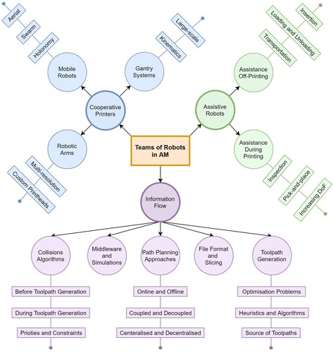
Therefore, this is the first review paper that provides an overall discussion on the concept and implementation of teams of robots in AM. The paper discusses the state-of-the-art of this concept from three aspects: cooperative printers, assistive robots, and information flow. summarises the key topics and subtopics discussed in this review. To familiarise the reader with overall concept of team of robots in AM, the paper starts with discussing the applications and implementations of teams of robots as cooperative printers and assistive robots. Then, the paper delves into the information flow of cooperative printing robots, discussing various topics such as the toolpath generation, collisions-related algorithms, and the use of simulations for teams of robots. Finally, the paper also discusses key research gaps, challenges, and opportunities to further develop this emerging area in the field of AM.
Figure 1. The main topics discussed in the review paper.
2. Cooperative printing robots
2.1. Cooperative printing gantry systems
Cooperative gantry systems comprise different kinematic configurations, including multi-nozzle (a) and multi-gantry (b) (Zhang and Khoshnevis Citation2013). Multi-nozzle gantry systems consist of a single platform that carries multiple nozzles. In this configuration, each nozzle is free to move on both X-axis and Y-axis independently, but the Z-axis is shared between printheads. On the X-axis the nozzles cannot cross each other. Multi-gantry systems comprise multiple gantries arranged next to each other, and each gantry controls a specific printhead. In this configuration the printheads cannot cross other printheads in the Y-axis, being free to move in any other direction.
Figure 2. Cooperative printing gantry systems. (a) Multi-nozzle, (b) Multi-gantry.
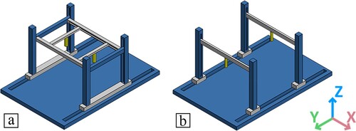
The gantry kinematic configurations proposed in the literature are limited due to the crossing prevention nature. This largely reduces effectiveness of the cooperative printing systems and affects the workspace of each printhead. A better kinematic system, though more complex, is the multi-arm configuration (). In this case, the cooperative system can move freely in all directions, being able to cross other nozzles if no collision is detected. The multi-arm configuration can be scaled to any number of printheads. shows three multi-arm configurations with a different number of printheads. A system with n number of printheads requires the printing platform to be shaped as a polygon with at least n sides.
Figure 3. The multi-arm gantry configuration.
The use of cooperative gantry systems for AM applications has been investigated by several research groups. Wachsmuth (Citation2008) developed a multi-nozzle gantry system for polymer applications. This system was the first reported cooperative printing system. The authorised commercially available printheads (filament-based systems) and added solenoids to lift the idle heads. The system required careful calibrations to guarantee the avoidance of collisions during the printing process. To test the system, the author fabricated a cube specimen that was deposited evenly between all the heads. The end-product showed mechanical properties nearly identical as if a single head was used, but the fabrication time was significantly reduced.
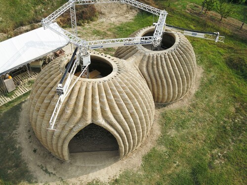
For construction applications, the Italian company WASP (Wasp. TECLA Citation2021), developed multiple crane 3D printers to build houses collaboratively (), using a wide range of materials such as concrete mortar, geopolymers, and natural waste materials derived from the rice production chain. However, due to the configuration of the system, the interaction between two machines is limited, reducing the overlap/cooperative area. This concept of small overlapping areas were also implemented by other researchers (Shen, Pan, and Qian Citation2019; Zhang et al. Citation2018). The lower the overlap area the more the system converges to multiple single-printhead systems working individually. Increasing the overlap area improves the capabilities of the cooperative printing system and allows more cooperation, however, collisions become more frequent. Thus, further research work is required to determine the best overlapping area that produce the optimal results with minimum side effects.
Figure 4. A shelter being built using two cooperative 3D printing cranes (Wasp. TECLA Citation2021) Credit: WASP.
Large AM machines used to produce large-scale parts present limited accuracy and part quality regarding small-scale features, due to accuracy fluctuations in the workspace (Tan et al. Citation2014; Feng et al. Citation2015). This problem can be addressed by using multiple gantries to fabricate large-scale parts, allowing to assign different printheads to different regions. Titan Robotics (U.S.A.) (Titan Robotics Citation2017) used this approach to fabricate large plastic parts. The system comprises five extruders (screw-based printheads) using polymers in the form of pellets. The system was capable of printing layers of heights as low as 0.1 mm. The machine build volume was 1830 mm × 762 mm × 502 mm.
2.2. Cooperative printing robotic arms
The use of cooperative robotic arms for AM is rapidly growing, as, contrary to the gantry systems, each robotic arm is independent of the other arms, which further simplifies the control and planning of the cooperative robotic system. Moreover, the workspace of robotic arms can be larger than the machine size.
Shen, Pan, and Qian (Citation2019) developed a multi-robot extrusion-based system for large-scale manufacturing. The system consists of four 3-axis robotic arms, a printing bed, and a nozzle attached to each robotic arm (a). The robots are arranged in parallel, and each line can have as many robots as needed. By this method, a part of any length can be printed. However, both the width and height of the printed part are constrained by the workspace of the robot. Therefore, the system is only able to print models that are large on one dimension but smaller on the other two dimensions. (b) shows a part produced by this cooperative system, which compared to a single robot allows to reduce the fabrication time by 73%. One of the limitations of this work is that no robot is allowed to work on the next layer unless all the other robots are finished from the current layer. This limitation is common in the literature of cooperative printing (Zhang and Khoshnevis Citation2013).
Figure 5. (a) Four robots cooperating on the fabrication of a single part; (b) example of a part made by the cooperative robots (Shen, Pan, and Qian Citation2019); (c) end-effector carrying 3 torches with 5 arcs, (d) 6-axis robotic arm holding the end-effector (Tianying et al. Citation2021).
The use of cooperative robots allows multi-resolution 3D printing, which is not possible with single robot AM machines unless the arm frequently changes the end-effector. Bhatt et al. (Citation2019a) investigated this feature of heterogeneous cooperative systems by using two 6-axis ABB robotic arms. In this case, one robot prints the surface in high resolution with a low nozzle size while the other robot prints the core in low resolution with a large nozzle. This system enables the printing of non-planar surfaces and reduces the printing time without affecting surface finishing. However, a delay between each robot is needed to avoid collisions. The cooperation in this system is weak as the two robots work independently of each other and there is no interaction between the robots. Also, due to the delays added, the fabrication time increases significantly. A system where the two robots work together at the same time reduces the printing time but complicates the planning aspect due to collisions chances.
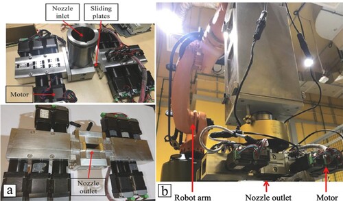
A robotic arm can also carry an end-effector with multiple cooperative printheads. Tianying et al. (Citation2021) developed a custom end-effector for directed energy deposition that incorporates 5 different arcs with 3 torches as shown in (c). Moreover, the end-effector controls the torches positions and rotations using five motors, and also controls a 6-axisKUKA robotic arm (d). Fabrication using the custom end-effector was performed by restricting the two arcs to form the contour of the layer being the contour filled by the other arcs. This system was used to produce a metal marine propeller bracket with forming efficiency reaching 1800 cm3/h. Custom printheads can also be used to address the staircase effect. For concrete printing, Lao, Li, and Tjahjowidodo (Citation2021) developed a variable-geometry nozzle consisting of a deposition module (inlet and outlet nozzles and a material flow channel) and two shape-varying units on both sides of the deposition system (). In total, 10 sliding plates acting as actuators were used to change the shape of the nozzle oulet.
Figure 6. Variable-geometry nozzle. (a) Different views of the nozzle, and (b) the nozzle mounted on a KUKA robot (Lao, Li, and Tjahjowidodo Citation2021).
2.3. Cooperative printing mobile robots
The use of mobile robots in AM is a new concept. The ability of a robot to move freely in a workspace opens new possibilities to AM and presents several advantages such as the large workspace that can be covered by mobile robots, only limited by cable length or battery capacity. Moving freely in a plane alongside having large workspace ease the task of collision avoidance which is a major obstacle for implementing cooperative robots in AM. Moreover, a mobile robot can carry a robotic arm onboard which further increases the usefulness of mobile robots and widen possible applications.
Several research groups investigated the use of cooperative mobile robots for AM based on the use of holonomic and nonholonomic robots, or multiple robots and swarm robots to process a wide range of materials such as plastics and concrete. A holonomic mobile robot does not have any constraints on its velocity while nonholonomic robots are subjected to a Pfaffian velocity constraint (Janiak and Tchoń Citation2011). Moreover, holonomic mobile robots can move sideways making the man ideal choice for 3D printing applications.
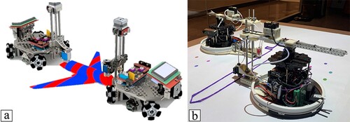
A mobile robot can be used as an AM machine by attaching a Z-axis stage to the base of the robot. Marques et al. (Marques, Williams, and Zhou Citation2017)from the AM3 Lab at the University of Arkansas (U.S.A.), developed two low-cost holonomic mobile 3D printers that print while moving. Each robot was equipped with a Z-axis stage, a printing nozzle able to print a wide range of plastic materials, and positioning sensors (a). Currently, there is no communication between the two robots, so a novel communication system is required to transform the system into a real cooperative system. The AM3 Lab (AMBOTS Citation2021) developed also a variation of the cooperative AM system using a robotic arm instead of the Z-axis stage. These works did not make use of global localisation sensors and instead only relied on local sensors. Therefore, the two robots cannot know each other locations and where each robot should be if both only know their locations based on the local reference point. Moreover, without global sensors, it is difficult, and time consuming to setup and calibrate the cooperative printing systems, as the operator must manually calculate the starting transformation matrix between both robots.
Figure 7. (a) An example of a holonomic cooperative mobile 3D printer (Poudel, Sha, and Zhou Citation2018), (b) two nonholonomic mobile 3D printers (Xu, Wang, and Feng Citation2021).
On the other hand, Xu, Wang, and Feng (Citation2021) used two nonholonomic mobile robots for material extrusion (b). Since their robots cannot move sideways, they attached a 2-axis robotic arm on top of each mobile robot to perform 3D printing tasks. Positioning the mobile robots was done using a regular projector and cameras, achieving millimeter-level visual servoing accuracy with both global and local sensors.
However, in all of the previously reported mobile robot applications, the quality of the produced parts was worse than the parts produced by other fixed robots. This is mainly due to the poor positioning of mobile robots compared to fixed robots. To achieve comparable results, better localisation systems need to be developed. Furthermore, wheels are very sensitive to manufacturing and assembly errors which lead to vibrations and inaccuracies. Additionally, omnidirectional wheels introduce vertical vibrations that further reduce the quality of the printed part (Xie et al. Citation2015).
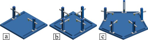
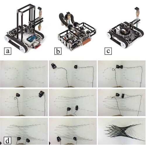
Another example of a cooperative mobile AM system for construction applications was developed by The Institute for Advanced Architecture of Catalonia (Spain) (Jin et al. Citation2013). The system is based on the use of three nonholonomic mobile robots. All robots take building material from an external concrete pump and mixer. The first robot is the foundation robot, as it lays the foundation of the structure by following a specified track on the ground (a). This robot has a vertical actuator that incrementally adjusts the nozzle height. Then, another robot climbs the foundation and deposits concrete by following the foundation path (b). The four rollers in this robot allow it to clamp onto the edge of the structure to deposit more concrete layers. Finally, the third robot uses vacuum cups to attach itself into the surface of the structure and reinforces the shell printed by the previous robots (c). Structural optimisation tools and finite element analysis software were used to create an optimised path for this last robot.
Figure 8. The Minibuilders used for construction applications. (a) Foundation robot, (b) grip robot, (c) vacuum robot (Jin et al. Citation2013), and (d) multiple cooperative mobile robots fabricating a woven-like structure (Yablonina et al. Citation2017).
Aerial mobile robots are currently being investigated as main systems for the bio-inspired concept of swarm 3D printing. This type of collaboration is inspired by nature where insects cooperate to construct large structures, such as termite mounds (Oxman et al. Citation2014). Aerial robots bring the advantage that each robot can move in three dimensions allowing them to easily avoid collisions and reach inaccessible places. A recent work explored this concept by developing several drone 3D printers called BuilDrones (Zhang et al. Citation2022). To counter the inaccuracies of aerial robots, a delta robot is attached to the drone and performs the printing process. The delta robot is a self-aligned manipulator that overcomes the disturbances caused by the drone during flight. The authors successfully printed several structures using this system as shown in . In a virtual printing experiment, they used three BuilDrones to cooperatively print a large structure. However, no cooperative physical printing was performed, and the sensor system used was designed to work within laboratory environments, limiting their use in outdoor environments. Moreover, the system shows a 6 mm median value of absolute positioning error for the printhead.
Figure 9. (a) The BuilDrone system printing a cementitious part, (b) three drones printing a virtual part, and (c) a simulation of eight robots printing a cylindrical part (Zhang et al. Citation2022).
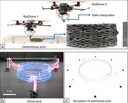
Both aerial and ground robots face several challenges when used for AM applications, especially in terms of positional accuracy, material stock and battery power. Current ground mobile robots suffer from poor positioning accuracy, and this issue is amplified in aerial robots as the current accuracies of these systems in isolation are in the centimetre ranges (Gerwen et al. Citation2022). The BuilDrones team overcame this issue by mounting an accurate delta robot on the drone. However, this increases the total weight preventing the system from carrying more material. Weight issues are particularly important for aerial robots, with researchers focusing on developing lightweight material specifically designed for aerial AM (Zhang et al. Citation2022). Similarly, as the robot cannot carry large amount of material, it is required to refill its stock frequently which significantly increases the printing time (Zhang et al. Citation2022). The refilling is usually manually performed, so the development of automated AM material refilling strategies for both ground and aerial systems are required. Finally, there is the problem of power consumption as AM equipment usually require high power compared to drones usage (Gutierrez-Osorio et al. Citation2019).
Moreover, as the concept of swarm 3D printers is hard to implement, several researchers developed computer simulation tools to evaluate their performance. Shepherd and Williams (Citation2017) carried out a simulation for 3D printing with a swarm of aerial robots. In this simulation, they imitated insects building a large column of a termite mound. Another simulation was developed by Krishnasreni et al. (Citation2014) to fabricate bridges between structures in high altitudes. The drones in the simulation are flexible in taking different formations and configurations, enhancing their ability to adapt in case of weather fluctuations. However, no physical systems have been reported.
Cooperative AM is not only applicable to macroscale manufacturing but also to micro manufacturing. An example was proposed by Cappelleri et al. (Citation2014) that designed a method for independent control of several magnetic microrobots. The designed system consists of specialised micro coils of similar size as the robots, used to generate magnetic fields to manipulate the trajectories of the robots. The system has been developed for the AM fabrication of smart devices, sensors, and actuators.
Due to the large workspace of mobile robots, they can be used for architecture and aesthetics applications. Yablonina et al. (Citation2017) developed a system that consists of multiple cooperative lightweight nonholonomic mobile robots. Each robot can sense the environment using a set of onboard visual sensors such as cameras. The control system allows the robots to localise within the environment and provides real-time path corrections. The robots were also designed to climb walls to fabricate structures in a 3D environment. Printed filaments are supported by anchors. (d) shows a sequence of steps illustrating the fabrication of an object.
3. Assistive robotic systems
In the context of AM, assistive robots can be used to increase the versatility of AM machines. Assistive robots are those that do not directly deposit or extrude material during the fabrication process. They are responsible for tasks that need to be implemented off-printing for preparation or during the printing process (e.g, pick-and-place or printing platform control).
3.1. Assistive robots off-printing
Assistive robots are beneficial for AM when used before or after the printing process. Such robots are used for the purpose of preparing the AM machine, performing tasks such as transportation, loading the machine with new materials, cleaning the printing platform, or inserting supports off-printing.
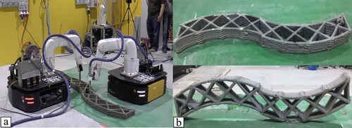
A common application is to transport the 3D printing machine to the desired location before the printing process starts. In this case, mobile robots are advantageous as they allow the machine to be portable and significantly increase the workspace. Multiple research groups have explored the use of mobile robots as transportation media (Li, Aubin-Fournier, and Skonieczny Citation2021; Keating et al. Citation2017). Zhang et al. (Citation2018) developed a team of mobile robots for construction applications based on 6-axis robotic arms mounted on holonomic mobile robots (a). For localisation and odometry of the mobile platforms, they used several sensors such as a laser scanner, stereo camera and markers, wheel encoders, and inertial measurement units. In this case, the mobile platform was used to carry the robotic arm moving it to the printing location. A moving while printing strategy was not implemented. Each robot was equipped with a printing nozzle that deposits concrete fed from an external pump and mixer system. A sample concrete structure is shown in b. The sample had high bonding strength allowing it to support its weight. However, the interface between the two sections is visible which indicates that a better positioning system is required.
Figure 10. (a) Mobile robots moving robotic arm to locations for concrete printing, (b) Example of a concrete printed structure (Zhang et al. Citation2018).
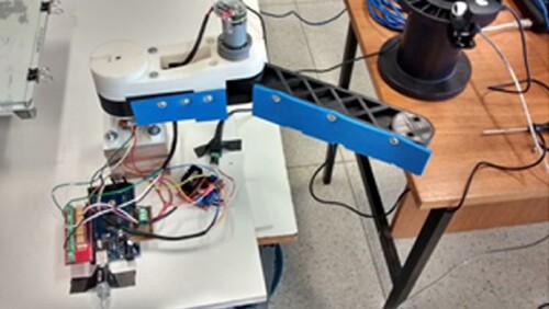
Usually, when a part is finished, the machine stops and cannot proceed until the part is removed. Hence, assistive robots can be used to pick the finished part and store it away from the printer. Aroca et al. (Aroca et al. Citation2017) developed a 2-axis robotic arm that removes the finished part by pushing it out of the printing platform (). The main limitations of this system, which was developed to produce plastic parts, are related to the part adhesion to the printing platform and the forces applied by the robot to remove the part which might damage it. In order to solve these limitations, Costandi et al. (Citation2017) used a FANUC robot to remove the printing platform when the process is finished, replacing it with a new one. The finished platforms are stored in a rack beneath the printer. However, this process is limited by the number of available printing platforms. Issa et al. (Citation2019) also developed a 2-axis robot to unload the finished part. However, they used a revolute-prismatic joint structure instead of a revolute-revolute one. Mobile manipulators have also been used to remove finished parts from the machine. Arrais et al. (Citation2019) developed a mobile system that moves from a docking station to the 3D printer when it finishes and grasps the part based on its geometry without collisions. The mobile manipulator then plans its path to the unit that requested the 3D printer to fabricate the part or to a warehouse.
Figure 11. The robotic arm responsible for pushing the parts. The blue side is what touches the part during the removing process (Aroca et al. Citation2017).
Concrete 3D printing largely benefits from assistive robots, as stacking concrete layers without reinforcement is limited to non-load bearing applications. Therefore, methods to introduce structural elements and other components are needed to increase the capability of concrete 3D printing. Hack et al. (Citation2020) developed an end-effector specialised on forming meshes before concrete printing. The developed system uses a mobile manipulator to install large-scale steel mesh that supports concrete printing. However, fully installing the steel mesh before 3D printing requires the manipulator to do several relocations to access all the points in the printing area. There are many attempts to develop systems that reinforce the concrete structure after the printing process is finished, for example by embedding fibres and metallic bars (Mechtcherine et al. Citation2021).
3.2. Assistive robots during printing
An important role for assistive robots is performing various tasks while printing to increase the versatility of AM machines. Such tasks allow AM to be used within full manufacturing and assembly systems.
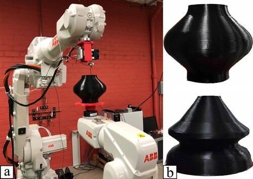
Assistive robots allow the printing platform to be actively controlled, increasing the degrees of freedom of the system. Furthermore, actuated printing platforms can be used to simplify the process of creating revolved parts. For example, Ding, Dwivedi, and Kovacevic (Citation2017) developed a laser-based directed energy deposition system that consists of a 6-axis KUKA robotic arm as the printer and a 2-axis tilt-rotary robot to control the platform. This system simplifies the process planning of multi-plane printing and reduces the required printing time. The system was used to produce revolved parts, such as propellers, which require support structures when made through traditional AM. Main limitation of this technique is related to the poor-quality surface finish due to oxidation, which requires further post-processing.
Support structure reduction or elimination is a prominent example of the use of assistive robots during printing. Bhatt et al. (Citation2019c) used an industrial 6-axis robot for material extrusion together with a robotic arm controlling a 3-axis platform (). This system allowed support-free structures (b), significantly reducing the fabrication time. A similar approach was used by Wu et al. (Citation2017a), but in this case, the printhead was fixed while a 6-axis robotic arm was used to control the platform. The authors also investigated the mechanical properties of parts produced by this system and similar parts produced using a conventional AM machine. Results showed that the parts produced by the proposed system exhibit relatively lower mechanical properties, mainly due to weak adhesion between layers. Further process optimisation is required.
Figure 12. (a) A 6-axis robotic arm printing on a platform controlled by a 3-axis robotic arm, (b) example of an object produced by the system (Bhatt et al. Citation2019c).
Gantry systems can also incorporate robot-controlled platforms to further enhance the manufacturing process. Gao et al. (Citation2015) developed a system called RevoMaker, which is a 1-axis rotational platform built on a low-cost material extrusion platform. The system allows the fabrication of functional prototypes requiring fewer support structures. This concept was also demonstrated by Grutle (Citation2015) on a 3-axis AM machine by developing a 2-axis build platform.
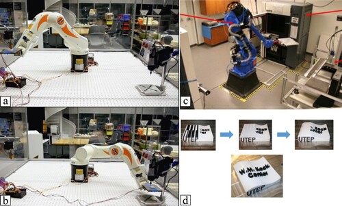
Assistive robots can be used for material transportation between different stations. This allows AM to be used as an intermediate step during manufacturing, which is impossible to automate without assistive robots. An attempt to use an assistive robot to move material between two stations was done by Keating and Oxman (Citation2013). They developed a unique manufacturing system that combines multiple technologies, including additive, formative and subtractive methods. In one of the applications, the authors used a 6-axis robotic arm to orient the platform bed during the printing process. Authors also used this robotic arm to move the part between two platforms, one for additive manufacturing and the other for surface milling (a and b). However, the subtractive robotic arm presented significant vibrations requiring further improvement. In this case another assistive robot might be helpful to support the part being built and to reduce the vibrations. Similarly, researchers at the University of Texas at El Paso (Ambriz et al. Citation2017; MacDonald and Wicker Citation2016) developed a material handling and registration system for AM. The proposed system comprises several functionalities such as material extrusion, machining, vision system, and an assistive robotic arm that moves components between chambers (c). The developed system can produce multi-coloured and multi-material parts (d), but the dimensional accuracy of the produced parts is affected by the frequent transportation of material between stations. To avoid such effect on the dimensional accuracy of printed parts, Nagamatsu et al. (Nagamatsu et al. Citation2020) developed a directed energy deposition system combined with both measurement and machining systems. The shape of the AM fabricated parts were measured using the Structure from Motion method and then machined to the target shape.
Figure 13. Assistive robotic system (a) A robotic arm is used to move the platform to a printing station and to (b) a milling station (Keating and Oxman Citation2013). (c) A robotic arm removes the platform from the first machine, (d) an example of a manufactured part (Ambriz et al. Citation2017; MacDonald and Wicker Citation2016).
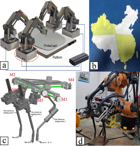
Another example of a mid-printing task is pick-and-place and inspection operations. Pick-and-place allows AM to produce functional parts by inserting different components in the part during the printing process. Researchers from the Georgia Institute of Technology (U.S.A.) (Roach et al. Citation2019) developed an AM machine called M4 which combines multiple AM technologies such as material extrusion, material jetting, and photo-curing (). The system also comprises two robotic arms for pick-and-place applications, conformal printing, and in-situ measuring. Moreover, the system uses five motion stages, one to control the X and Y positions of the bed and the other four to control the Z position of each printhead. The system was used to fabricate a light-emitting diode (LED) by printing the case using the extrusion systems and inserting the required electronics inside the case. However, the insertion tasks are not fully automated, being performed by an operator that must place the item in a specific position and orientation so that the robot can correctly pick the item and place it in the correct location. Felsch et al. (Citation2017) also designed a manufacturing system that includes multiple extruders and two robots. During printing, the main robot controls the position and orientation of the build platform, while the second robot places metallic inserts inside the part while it is being printed. Drones are also used for the inspection of 3D printed parts as recently presented by Buswell et al. (Citation2020) that developed a system in which a drone was used to scan and inspect 3D printed concrete structures for further verifications.
Figure 14. The M4 printer showing all the panting heads and the robotic arms (Roach et al. Citation2019).
Assistive robots were used by Relativity Space (U.S.A.) to build the world’s first 3D printed rocket (Relativity Space Citation2020). The developed AM system uses directed energy deposition technology to build various rocket parts such as a large fuel tank. In this machine, three robotic arms work collaboratively. The main arm feeds out metal on a rotating table, using a laser to melt a metallic wire. The other two arms assist the printing arm by holding working tools that are required for finishing purposes. The system is reported to produce parts with mechanical properties designed to meet the critical nature of aerospace structural requirements.
4. Information flow
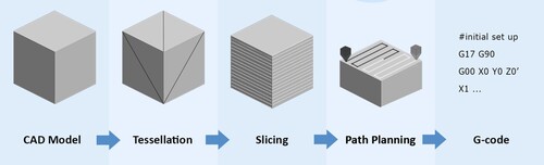
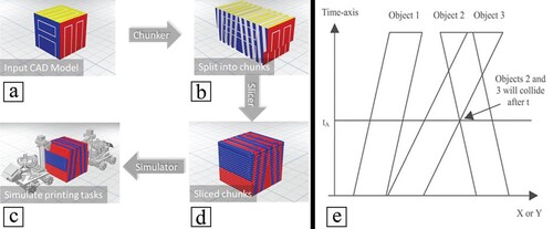
The typical information flow in AM is illustrated in . First, the 3D model must be created in a CAD system or generated through a reverse engineering process. This digital model must be represented as an enclosed volume. The CAD model is then tessellated and converted to a STereoLithography (STL) file, which is a triangular faceted surface representation like a finite-element mesh. However, the STL format does not include any information regarding material properties, thus not being able to represent functionally graded objects and complex 3D shapes using multiple materials. The Additive Manufacturing File (AMF) format has been developed to be an alternative to STL (Hiller and Lipson Citation2009). Contrary to the STL format, AMF is not limited to geometrical data, and includes material information such as texture, colour, and material properties. A slicing procedure is then applied to the STL model, generating a set of 2D layers comprising the contours that represent the material boundaries of the part to be generated. Finally, the path planning is defined and a G-code file, containing all the instructions to the machine, is created.
Figure 15. Typical information flow for additive manufacturing.
The slicing procedure comprises two main approaches: unidirectional slicing and multidirectional slicing (Ding et al. Citation2016). The unidirectional slicing approach, commonly used for gantry systems, generates layers that are parallel to a fixed build direction. The slicing procedure is mathematically simple and comprises uniform slicing that generates layers with the same thickness, and adaptive slicing that varies the thickness based on the position of the layer (Mao et al. Citation2019). Contrary, the multidirectional method slices the part considering multiple build directions. This method is mathematically more complex but reduces or eliminates the need for support structures (Xu et al. Citation2018).
Path planning, performed after the slicing operation, involves generating the material printing toolpath considering multiple robots, avoiding collisions and ensuring the path iscollision-free and kinematic-feasible (Yang et al. Citation2019). Popular toolpath patterns include raster, zigzag, spiral, contour, continuous, and hybrid patterns (Manoharan and Kumaraguru Citation2018). The choice of the toolpath patterns is directly related to the strength of the printed part (Jiang and Ma Citation2020). Collisions should be considered when choosing the filling technique. Path planning can be classified based on the algorithm used, online or offline, and coupled or decoupled (Wu et al. Citation2017b). Online planning is used when moving objects are unpredictable while offline planning is better suited for static environments and when objects move slowly, which is usually the case of AM. Coupled planners treat the robots as a single entity and search the configuration space of the robot, while decoupled planners compute the path for each robot independently, then planning a collision-free path for each robot (van den Berg et al. Citation2009).
Furthermore, the path planning can be either centralised or decentralised (Chen, Rosolia, and Ames Citation2021). In a centralised approach, one controller is responsible for planning the paths of all the robots in the system. This allows the system to be able to produce optimal paths as one entity has the global vision of where each robot must be and possess the information of every part of the system. Limitations of centralised path planners include hard-to-scale and reduction of robustness (Madridano et al. Citation2021). In decentralised planners, the decision-making process and information processing are spread across the robots in the system. However, decentralised systems are complex and often produce suboptimal solutions (Turpin, Michael, and Kumar Citation2012). For cooperative printing, centralised planners produce efficient solutions with improved printing time for problems with small number of robots and tasks, while decentralised planners are more suitable for large-scale problems (Poudel et al. Citation2023). However, the cooperative AM field is still not mature enough to provide a robust comparison between these two approaches. Therefore, further investigations are required especially in terms of the optimum problem size to achieve better solutions with minimum computation time, planning of assistive robots alongside cooperative printers, and recovery from failures for decentralised systems during printing.
4.1. Collision checking and avoidance
Collision checking corresponds to a group of algorithms used to determine potential collisions between printheads, while collision avoidance corresponds to algorithms that aim to resolve possible collisions. During path planning, collisions can be prevented by preparing the toolpaths beforehand, or checking collisions and avoiding them during the toolpath generation. The choice between these two methods affects the computing time, toolpath optimality and the quality of the produced part.
Collision prevention before toolpath generation is done as follows (Shen, Pan, and Qian Citation2019). Collision-free regions are determined then layer filling techniques are applied to the different regions. Each region is assigned to each printhead in the system. The advantage of this method is that it guarantees that any toolpath generated is collision-free. However, the toolpaths near the border regions require further checking. As a consequence of using this method, outer walls that span multiple regions must be printed by different printheads. This compromises the quality and the surface finish of the part as the outer wall lines are not continuous but disconnected and touch each other at the splitting lines.
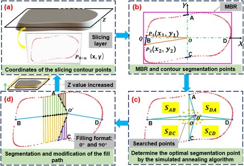
One method for collision checking before toolpath generation is to equally divide the layer to be printed into the number of printheads. Zhang and Khoshnevis (Citation2013) developed a system using this method to ensure that all nozzles finish the printing process at the same time. This method of equal division was also used by Shen et al. (Shen, Pan, and Qian Citation2019). Their algorithm finds the solution in four steps. First, the slicing contour points are determined (a), and then, using the minimum bounding rectangle (MBR) and Straddle Test methods, the intersection of the coordinate axes with the previously determined contour lines are computed (b). Then, the total area is divided into four regions (one region for each robot) using a Simulated Annealing optimisation algorithm (Kirkpatrick, Gelatt, and Vecchi Citation1983) (c). Finally, a filling pattern is used to generate the toolpath (d). However, the robots might collide when working on regions that are close to the splitting lines. Therefore, the authors divided each area into safe and interference areas. An interference area is only occupied by one robot at a time to eliminate the risk of collisions. The concept of safe/interference areas was also explored by Wang et al. (Wang et al. ).
Figure 16. The process of generating a printing path for each robot (a) determining slicing contour points, (b) computing the intersection of contour lines and coordinate axes, (c) dividing the areas, (d) filling each area (Shen, Pan, and Qian Citation2019).
Another relevant method for collisions checking before toolpath generation is the chunk-based slicing. McPherson and Zhou (Citation2018) developed this concept for their cooperative material extrusion systems. In this method, the CAD model is sliced into inclined chunks followed by a traditional slicing procedure (a–d). Each robot is responsible for printing some of the sliced chunks. However, the first chunk must be printed by a single robot. The inclined chunks allow mobile robots to print without interfering with each other. Therefore, the slicer procedure needs to take into consideration both the distance between the extruder and the body, and the nozzle dimensions to determine the minimum and maximum slicing angles. The chosen angle largely affects the mechanical properties of the part as the lower the angle the higher the contact area between chunks. This was also observed by Poudel, Sha, and Zhou (Citation2018) that found that based on the slicing angle, parts made with chunk-based slicing show between 121% and 61% of the tensile strength of parts produced without chunks.
Figure 17. (a-d) Chunk-based slicing process (McPherson and Zhou Citation2018). (e) Collision between two 1D objects in space-time (Zhu and Yu Citation2002).
It is also possible to check for collisions during toolpath generation (Bui et al. Citation2020). This is performed by generating toolpaths equal to the number of printheads and then checking for collisions. If there are no collisions and the paths are optimised, the paths are assigned to the printheads. This method, as it checks all the all toolpaths, can generate toolpaths that are unobtainable by the other method. However, the computational resources are large.
Usually, the collision avoidance is the bottleneck in terms of computational time, as it requires the replanning of the toolpath. Thus, some researchers avoid the expensive replanning by introducing delays or pausing one of the printheads. For example, (Choi and Zhu Citation2010) developed an approach based on decoupled path planning, through which the paths of all tools are independently planned. When two printheads are about to collide, the one with lower priority is paused at a suitable point until collision is no longer possible. Priorities are set based on the traverse speed of the tool, with the higher priority being assigned to the tool with higher traverse speed. The introduction of delays was also implemented by Bui et al. (Citation2019) for cooperative gantry AM. In their algorithm, collisions are avoided by introducing delays to one of the printheads. However, if the delay time cannot eliminate the collision, the system stops the cooperative operation mode, allowing only one printhead to operate.
The collision avoidance techniques detailed in the literature revolve around either introducing delays (Bui et al. Citation2020) or replanning the problematic path until collisions are avoided (Shen, Pan, and Qian Citation2019). Introducing delays increases the fabrication time and reduces the effectiveness of cooperative printing systems. On the other hand, the complete path replanning corresponds to a waste of computational power and increases processing times. Thus, novel collision avoidance algorithms are needed to both reduce the printing time and the computation time needed to path plan the layer.
There are different algorithms for collision checking. One of them is called spatio-temporal collision checking which was investigated by Zhu and Yu (Citation2002) in their system for multi-material cooperative AM. Through this method, 2D layers are extruded into 3D shapes in space–time. The intersection between different toolpaths in space–time means that the printheads will collide at that time (e). In this case, the collided areas are not filled simultaneously, or the toolpath needs to be changed. Jin, Pierson, and Liao (Citation2019) also applied this collision checking method for their path planning algorithms for cooperative printing systems. Other examples of algorithms generating collision-free paths include probabilistic roadmap (Clark Citation2005), rapidly exploring random tree (Desaraju and How Citation2011), and virtual potential fields (Song and Kumar Citation2002). These algorithms are used to coordinate motions for collision avoidance during printing or when depositing is paused.
Collisions are not always between different printheads. Sometimes they also occur between the links of a printhead, such as for robotic arms. Moreover, the feasibility of the path planning often requires some printheads to have different priorities. In the case of cooperative AM, these issues were explored by Cai and Choi (Citation2019), which developed a strategy to check collisions based on three spatial constraints: distance-based, region-based, and position-based constraints. The distance-based constraint ensures no collisions between two printheads if the printing areas are close to each other. The region-based constraint considers collisions between a printhead of a robot and the links of the other robots. Finally, in the position-based constraint, actuators must follow a material deposition order.
4.2. Toolpath generation
The task of toolpath generation is concerned with determining the travel and printing motion for each printhead in the cooperative printing system. Solving for the toolpath is an optimisation problem with constraints and an objective function (Wah et al. Citation2002) and it is not unique to AM being extensively investigated for machining operations (Castelino, D'Souza, and Wright Citation2003). The constraints of the optimisation problem for cooperative printing include different factors such as collisions, deposition order, and traversing printing lines (Jiang et al. Citation2020b). The objective function selects which is the best toolpath based on certain criteria. Usually for a single printhead machine, the total printing time is considered as the objective function (Jiang and Ma Citation2020). However, for cooperative printing systems, the difference between the largest and smallest printing time of the printheads is also important.
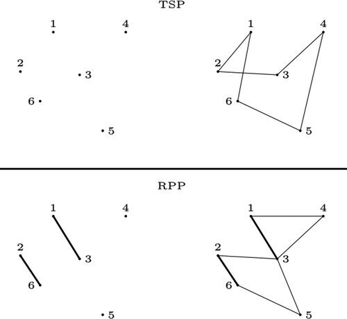
The starting and ending points of each line in the toolpath are either custom determined or taken directly from a readily available slicer software. After finding these points, the toolpath generation problem must be formulated. There are several reported attempts that formulate the toolpath generation as an optimisation problem. Two of these formulations are the Traveling Salesman Problem (TSP) (Ganganath et al. Citation2016) and the Rural Postman Problem (RPP) (Iori and Novellani Citation2020) (). The TSP is concerned with finding the shortest Hamiltonian cycle that connects all the nodes in a graph. The RPP, on the other hand, tries to identify the shortest Euler cycle connecting all the required edges in a graph. Both TSP and RPP are proven to be NP-Hard problems (Jünger, Reinelt, and Rinaldi Citation1995). In the TSP any node can be connected to any other node. This is not applicable for toolpath generation of AM, as printing lines that connect two points must not be changed. Therfore, some researchers use the RPP instead of the TSP for the toolpath generation problem (Fok et al. Citation2018). However, the TSP can be transformed to the RPP and vice versa (Baldacci and Maniezzo Citation2006). There are several variations of these problems that can be used for toolpath generation and additional information can be found in (Monnot and Toulouse Citation2014; Eiselt, Gendreau, and Laporte Citation1995). To solve these problems different heuristics and metaheuristics are used.
Figure 18. Example of the TSP and RPP formulation (left side) and sample solution (right side). Any node in this example can be connected to any other node and thick lines are required lines for the RPP.
One of the heuristics for solving a TSP is the 2-Opt algorithm (Englert, Röglin, and Vöcking Citation2013). Bui et al. (Citation2019) combined a significantly modified 2-Opt with Tabu Search metaheuristic (Glover and Laguna Citation1998) to solve the toolpath generation problem for amulti-nozzle cooperative gantry. The first algorithm locally changes the solution while the Tabu Search algorithm changes it globally. Zhang and Khoshnevis (Zhang and Khoshnevis Citation2013), used the Lin-Kernighan heuristic (Helsgaun Citation2000), a generalisation of the 2-Opt algorithm, to solve the toolpath generation after formulating it as a TSP. As reported, the found solution saved in average 47% of the total printing time.
Greedy algorithms are also used for solving the toolpath generation problem. Jin, Pierson, and Liao (Citation2019) used two greedy algorithms in their cooperative printing systems. The two heuristics use the Longest Processing Time First (LPT) algorithm (Graham Citation1969). The first heuristic allocates the longest path to the first printhead and the second longest path to the second printhead. The algorithm repeats the process until all printheads are allocated to a path. The second heuristic constructs the convex hull of each path and then offsets them by the size of the printhead, determining overlapping areas. Then the process follows the first heuristic but instead of considering the longest path, it uses the highest overlapping area. These algorithms are computationally slow, but the second is faster since it reduces the number of collision checks. However, authors ignored the collisions between the links that carry the printheads. A metaheuristic can be used as well. An example is the work of Jiang et al. (Citation2020b) for the toolpath generation of a cooperative gantry AM system. In this case, authors divided the printing path of each layer into sub-paths that were assigned to different printheads. The sub-paths were chosen using an Evolutionary metaheuristic (Vikhar Citation2016) with the objective function of minimising the printing time. The printheads were assigned using the LPT algorithm. A reduction of printing time between 23.3% and 41.2% compared to single nozzle printers was reported.
Generating and allocating the toolpaths are not enough to ensure the cooperative printing system execute them perfectly. The software must also check for uncertainty and errors in the system and account for them. Thus, it is important for the system to be fully calibrated before the robots start performing the generated toolpaths. One popular technique for calibration is to print a part by each robot in the system without cooperation and then correct the deviations in the software (Wachsmuth Citation2008). However, this method is not as effective for mobile robots due to the large number of uncertainties and disturbances during motion. Thus, an accurate global sensor that knows the location of each robot accurately and compensate for errors during planning is still required. Due to these uncertainties and the need for global sensors, offline path planning and toolpath generation is less effective for mobile robots (Marques, Williams, and Zhou Citation2017). However, online path planning for cooperative printing systems is largely unexplored in the literature.
4.3. Middleware and simulations
A middleware is the link between the operating system and applications. It typically manages the connection between various parts of the robot such as the actuators and the sensors within the system. In return, the middleware allows software developers to simplify designs, create modular components, and easily communicate with the hardware (Elkady and Sobh Citation2012). A component should be designed once and implemented anywhere, allowing ‘plug and play’ of different modules (Namoshe et al. Citation2008).
A wide range of commercially available or open-source middleware can be used to control a robot or a team of robots. Miro (Kraetzschmar et al. Citation2001) is an object-oriented middleware designed for teams of robots. It provides two services to communicate with the robot. The first service is addressing the sensors and actuators on the robot platform. The second is the framework of classes that provide the programmer with different design patterns for robot control. The framework consists of multiple modules such as planning, vision, and mapping, allowing communication between multiple platforms and systems. Graphical user interface and visualisation tools in Miro utilise the Qt toolkit. Another middleware used for robotics is Orca (Brooks et al. Citation2007), which is an open-source framework that applies component-based systems to robotics. It allows users to develop building blocks that can be combined to create a functional robotic system. Orca does not support real-time applications, which cannot be considered a major problem for AM applications unless the system moves unpredictably. A more popular middleware is Player (Kranz et al. Citation2007; Kranz et al. Citation2006), that provides users with interfaces allowing them to communicate with actuators and sensors. The system consists of two layers, the core and transport layers. The core layer includes all the classes needed for drivers and devices in the system as well as configuration files. The transport layer is dedicated to communications by using Transmission Control Protocol (TCP). Player has been previously used for cooperative mobile robots in manufacturing environments (Naidoo, Bright, and Stopforth Citation2016).
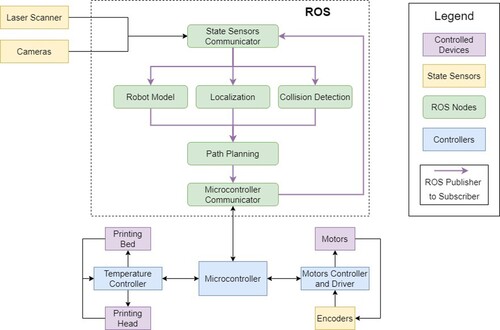
However, the most popular and most developed middleware is the Robot Operating System (ROS) (Koubaa Citation2016; Quigley et al. Citation2009). ROS is open-source and designed to be extendable by the community. It features a collection of tools and functions that simplifies communications with robots, and includes different graph concepts, such as nodes, topics, and messages. Nodes are executables that communicate with other nodes (e.g. a node that controls the extruder and another node that measures the nozzle temperature). Topics are buses that exchange data between nodes. Messages are the data transferred between topics. One of the communications means in ROS is the publisher/subscriber model where a node publishes or subscribes to a topic. ROS allows the user to integrate it with other frameworks such as OpenRAVE and Player. It also supports a wide range of actuators, sensors, and robots in the market. ROS has been used in cooperative AM mainly for device control and communications (Zhang et al. Citation2018). However, it is not dedicated to real-time applications and was not developed for cooperative robots. However, these limitations were addressed through the development of ROS2 allowing its usage for cooperative robots and real-time robotic applications (Why ROS Citation2? Citation2021). shows how ROS can be used as a middleware for an AM system based on mobile robots, which can be easily expanded for cooperative AM.
Figure 19. An example of ROS architecture for an AM system using a mobile robot.
Simulators are another type of software needed for cooperative mobile robots. The purpose of a simulator is to test the system in a virtual environment, ensuring that no collisions or obstacles occur. Different 2D and 3D simulators have been developed. 2D simulators, such as Stage (Vaughan Citation2008), can be used to simulate the layer filling pattern or printhead motion in a plane. However, 3D simulators are more suited for AM applications. CoppeliaSim (previously V-REP) (Freese et al. Citation2010) is a modular and decentralised robotic simulation software, and the ideal candidate for a complex system that contains sensors and actuators operating at different rates. CoppeliaSim programmes can be written in multiple programming languages such as C++ and MATLAB and can also be integrated with ROS. Another popular 3D simulator is Gazebo which is used for both single and multiple robots (Noori et al. Citation2017) and AM applications (Alhwarin et al. Citation2015). It is also integrated with ROS, and both are maintained by Open Robotics (U.S.A.). Multiple physics engines, such as Open Dynamics Engine and Bullet, can also be used with Gazebo (Erez, Tassa, and Todorov Citation2015).
5. Discussion
The use of cooperative robots for AM represents an emerging area of research. Despite the significant advantages offered, this challenging concept is relatively new, and many obstacles must be overcome for it to shine. This section will detail how AM benefits from cooperative robots and present the current challenges and future perspectives.
5.1. Improvements to AM
Teams of robots bring several improvements to AM, including multi-material and multi-method improvements, versatility and full automation of AM machines, improving performance by reducing fabrication time, and workspace efficient utilisation.
Multi-material improvements: currently, multi-material printing and the combination of different AM printing techniques usually requires the use of a mechanism that completely replaces the printhead with a different one (Vasquez et al. Citation2020). However, this implementation limits the type and size of the tool heads, and significantly increases the printing time due to the frequent changes between the different heads as only one printhead can be active at a time. In cooperative printing systems this is no longer a problem as more than one printhead can be operated at a time. This offers high levels of efficiency, which are not fully explored. Examples of multiple printheads or the use of different printing principles were presented in this review as well as the combined use of additive and subtractive strategies.
Versatility: the unique characteristic of AM where an object is built layer-by-layer, allows additional operations to improve AM, increasing its versatility. This is mainly achievable using assistive robots. An example is the full integration of pick-and-place operations allowing for example sensors and actuators to be fully enclosed without the need of welding operations or the use of fasteners. Other examples are related to the use of assistive robots for material handling and transportation, in-situ measurement, tools holding, and cleaning/removal of the printing platform.
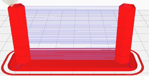
Performance improvements: a well-known limitation of conventional AM is the printing time, usually higher than the fabrication time of subtractive manufacturing methods. For example, material extrusion of plastics is on average 62% slower than plastics machining (Urbanic and Saqib Citation2019). Cooperative printing can significantly accelerate the fabrication time, making AM a more competitive technology in terms of speed. The maximum time reduction when using cooperative systems is theoretically where n is the number of printheads (Jiang et al. Citation2020b, Wang et al. Citation2017). In cases where the printing process requires long travel movements the use of cooperative systems can significantly reduce this, accelerating the fabrication time even further than the previous ratio. An example is shown in presenting a part with two features far away from each other. If a single robot system is used, it must travel between these two features in addition to print them. However, the negative impact of travelling distance on the overall fabrication time can be minimised considering a cooperative printing system with two printheads each printing a feature without travelling. However, for normal parts, this is rarely the case. Thus, the previous ratio will be considered as the maximum possible time reduction ratio. Due to practical considerations such as idling time and potential collisions, this ratio is smaller in real systems. For example, it has been observed through simulations that the use of four printheads allows to reduce the time by 64% instead of the theoretical 75% (Leite et al. Citation2018). However, the practical ratio can approach the theoretical maximum for different systems. Wang et al. (2017) conducted a set of simulations showing that four printheads can reach up to 69% time reduction. Moreover, Shen, Pan, and Qian (Citation2019) reported to achieve a 73% time reduction when using four printheads. The lowest of these reported ratios make material extrusion faster than plastic machining.
Figure 20. The retraction test where a printhead travels between two cylindrical columns.
Workspace utilisation: the efficient use of the workspace is a generic challenge in AM, as some regions within the workspace of the machine may not be usable or optimum to work on due to different factors such as singularities, vibrations, and accuracy fluctuations (Liu, Wu, and Wang Citation2019). Singularities avoidance is critical in the path planning of robotic arms. The configuration in which a robot is unable to move in certain directions is called a singular configuration (Lynch and Park Citation2017). If the robot is near a singular configuration several problems may arise, such as the velocity and torque of the joints may be unbounded, and a unique solution of the inverse kinematics cannot be achieved (Spong, Hutchinson, and Vidyasagar Citation2006). The presence of multiple robots in a cooperative AM system can be exploited to avoid singularities. For example, a printing area that is near a singular configuration of a robotic arm can be assigned to another arm in the system that is far from singularities in that region. The same strategy can be used to avoid configuration exhibiting high vibrations or regions with high accuracy fluctuations.
5.2. Challenges and future perspectives
The concept of teams of robots in AM iscomplex and challenging. There are various obstacles that slow down its development and progress. Overcoming these obstacles will affect the future of AM positively. This section lists these challenges which are avenues for future research works, as the gap on the current literature primarily revolves around them. Some of these challenges and research gaps are:
Gantry systems configurations: Current kinematic configurations for gantry systems are limited in many areas that result in poor utilisation of the concept of cooperative printing. For example, the two proposed configurations in the literature prevent any two printheads from crossing each other. In this review paper, we showed one configuration that overcome this limitation. However, further development of gantry configurations is needed.
Mobile robots design challenges: The use of cooperative mobile robots is an emerging area in AM. However, these systems require better positioning and localisation methods (Tiryaki, Zhang, and Pham Citation2020). Odometry data is not enough for a mobile robot to have accurate positioning since errors accumulate over time (Ganganath and Leung Citation2012). Thus, it is necessary to consider multiple sensors such as inertial measurement units, cameras, ultrasonic beacons, and laser range scanners. Fusing sensors’ measurement increases the accuracy of the AM system, but more data needs to be stored and processed. However, the required accuracy and precision depend on the application, for example, material extrusion with small nozzle diameters requires higher precision than those with larger nozzles such as in concrete 3D printing. Furthermore, there are practical considerations that need to be considered, for example, the developer needs to decide between cables and batteries. Cables limit the workspace and the motion between robots while batteries limit communication means to wireless only. Moreover, the capacity of the batteries limits the printing time unless a self-charging robot is used, which further increases the costs and complexity of the system. Cables further complicate the task of collision avoidance. Mobile robots also face challenges in terms of power consumption and material stock refilling. No work currently implemented automatic material stock refilling for mobile robots.
Path planning approaches: More investigation of different path planning approaches on cooperative printing, such as when to choose a centralised or a decentralised system and the optimum number of robots for a certain part. Also, offline path planning is dominant in the literature of cooperative printing, further development of online path planning techniques is needed.
High computation time: the path planning of cooperative printing systems, due to collision avoidance, deposition order, and synchronisation and calibration of movements of different printheads, is significantly different than traditional AM systems. Collision avoidance is a critical issue in path planning of cooperative printing systems. Moreover, due to the calculation of collision checking and avoidance, path planning takes longer times than single printhead systems (Bui et al. Citation2020; Jin, Pierson, and Liao Citation2019). For example, a single layer in Cura software for one printhead system is planned (including slicing) almost instantly, but in the case of cooperative printing systems, it has been reported that multiple printheads planning takes from few seconds up to 5 min in one study (Jin, Pierson, and Liao Citation2019) and up to 7 min in another (Bui et al. Citation2020).
Toolpath generation problem: in cooperative printing systems, the question of which printhead starts first and where, is a challenging question that requires further research. Furthermore, the motion of the robots must be synchronised and calibrated, as a small deviation between calculated and real positions of two printheads may results in a shifted unusable part. This is a critical problem as there is no readily available standard software for cooperative AM slicing and path planning, which represents an important adoption barrier.
Uncertainty and calibration: Due to the nature of cooperative systems, usually employing multiple printheads, uncertainty and positional errors are determinantal on the process results. A small deviation between any two printheads result in a part that is shifted and with print lines that are not well adhered. Current calibration processes are mainly manual, so new calibration methods are required for the automation of cooperative systems.
Monitoring requirements: most popular AM machines, especially desktop material extrusion systems, use open-loop control to actuate the motors. This is acceptable for systems that include end stop switches that detect the collision between the printheads and the structure of the machine, but not for teams of robots systems. The path planner that generates collision-free toolpaths for cooperative systems assumes that the system executes the generation motion perfectly. However, in open-loop systems, this is not guaranteed especially if there are external factors that increase the chance of collisions, such as belt slipping, uncalibrated motion, outside intervention, and stuck particles. Therefore, in the case of multiple robots systems it is important to have a method that verifies the motion of every part in the system. This can be done by implementing closed-loop control systems with monitoring capabilities using different sensors, such as rotatory encoders and cameras.
Middleware and simulators: There are no middleware or simulators developed dedicated to teams of robots in AM. As this concept is new and promising, a software for this system will streamline the development of various algorithms for cooperative robots in AM.
6. Conclusions
AM is mainly performed by systems that utilise a single robot. Such systems present various limitations such as the long printing time. However, the concept of teams of robots, which is already being used in other manufacturing processes, can be extend to AM. This concept eliminates some of current AM limitations, improving system versatility and productivity, also enabling new possibilities for the combination of different printing methods using multiple printing heads.
Teams of robots in AM comprise cooperative printers, and assistive robots. In cooperative printing systems, the printing task is divided between the printing heads in the system which largely reduces the fabrication time. Assistive robots, on the other hand, do not directly help in the printing process but in performing tasks that are needed before, during, or after the printing process such as loading and unloading the machine. Both types were discussed in detail in this review paper. In addition to the requirement of path planning and collision avoidance algorithms, cooperative AM requires slicing and proper processing parameter-material characteristics correlations. Various techniques and algorithms have been used to solve these problems, each with its own advantages and disadvantages. These solutions were reviewed in this paper alongside a description of middleware and simulators that can be used for teams of robots in AM. This review paper provides also new avenues for further research activities aiming to address key challenges and to fully improve this important domain of cooperative robots in AM.
Disclosure statement
No potential conflict of interest was reported by the author(s).
Additional information
Funding
References
- Alhwarin, F., A. Ferrein, A. Gebhardt, S. Kallweit, I. Scholl, and O. Tedjasukmana. 2015. “Improving Additive Manufacturing by Image Processing and Robotic Milling.” 2015 IEEE International Conference on Automation Science and Engineering (CASE). p. 924-9. doi:10.1109/CoASE.2015.7294217.
- AMBOTS. 2021. http://www.ambots.net/.
- Ambriz, S., J. Coronel, B. Zinniel, R. Schloesser, C. Kim, M. Perez, et al. 2017. “Material Handling and Registration for an Additive Manufacturing-Based Hybrid System.” Journal of Manufacturing Systems 45: 17–27. doi:10.1016/j.jmsy.2017.07.003.
- Aroca, R. V., C. E. H. Ventura, I. De Mello, and T. F. P. A. T. Pazelli. 2017. “Sequential Additive Manufacturing: Automatic Manipulation of 3D Printed Parts.” Rapid Prototyping Journal 23 (4): 653–659. doi:10.1108/rpj-02-2016-0029.
- Arrais, R., G. Veiga, T. T. Ribeiro, D. Oliveira, R. Fernandes, A. G. S. Conceição, et al. 2019. “Application of the Open Scalable Production System to Machine Tending of Additive Manufacturing Operations by a Mobile Manipulator.” Progress in Artificial Intelligence. Lecture Notes in Computer Science. p. 345-56. doi:10.1007/978-3-030-30244-3_29.
- ASTM. ISO / ASTM52900-15. 2015. Standard Terminology for Additive Manufacturing – General Principles – Terminology. West Conshohocken, PA: ASTM International. doi:10.1520/F2792-12.
- Aydin, L., and S. Kucuk. 2018. “A Method for More Accurate FEA Results on a Medical Device Developed by 3D Technologies.” Polymers for Advanced Technologies 29 (8): 2281–2286. doi:10.1002/pat.4339.
- Badarinath, R., and V. Prabhu. 2021. “Integration and Evaluation of Robotic Fused Filament Fabrication System.” Additive Manufacturing 41: 101951. doi:10.1016/j.addma.2021.101951.
- Baldacci, R., and V. Maniezzo. 2006. “Exact Methods Based on Node-Routing Formulations for Undirected arc-Routing Problems.” Networks 47 (1): 52–60. doi:10.1002/net.20091.
- Bártolo, P. J., and I. Gibson. 2011. History of Stereolithographic Processes. Stereolithography, 37–56. Boston: Springer.
- Bhatt, P. M., A. M. Kabir, R. K. Malhan, B. Shah, A. V. Shembekar, Y. J. Yoon, et al. 2019a. “A Robotic Cell for Multi-Resolution Additive Manufacturing.” 2019 International Conference on Robotics and Automation (ICRA). p. 2800-7. doi:10.1109/icra.2019.8793730.
- Bhatt, P. M., A. M. Kabir, M. Peralta, H. A. Bruck, and S. K. Gupta. 2019b. “A Robotic Cell for Performing Sheet Lamination-Based Additive Manufacturing.” Additive Manufacturing 27: 278–289. doi:10.1016/j.addma.2019.02.002.
- Bhatt, P. M., R. K. Malhan, and S. K. Gupta. 2019c. “Computational Foundations for Using Three Degrees of Freedom Build Platforms to Enable Supportless Extrusion-Based Additive Manufacturing.” Additive Manufacturing; Manufacturing Equipment and Systems; Bio and Sustainable Manufacturing, doi:10.1115/msec2019-3024.
- Bhatt, P. M., R. K. Malhan, A. V. Shembekar, Y. J. Yoon, and S. K. Gupta. 2020. “Expanding Capabilities of Additive Manufacturing Through use of Robotics Technologies: A Survey.” Additive Manufacturing 31. doi:10.1016/j.addma.2019.100933.
- Bin Ishak I, J. Fisher, and P. Larochelle. 2016. “Robot Arm Platform for Additive Manufacturing Using Multi-Plane Toolpaths.” 40th Mechanisms and Robotics Conference. doi:10.1115/detc2016-59438.
- Boparai, K. S., R. Singh, and H. Singh. 2016. “Development of Rapid Tooling Using Fused Deposition Modeling: A Review.” Rapid Prototyping Journal 22 (2): 281–299. doi:10.1108/rpj-04-2014-0048.
- Bos, F., R. Wolfs, Z. Ahmed, and T. Salet. 2016. “Additive Manufacturing of Concrete in Construction: Potentials and Challenges of 3D Concrete Printing.” Virtual and Physical Prototyping 11 (3): 209–225. doi:10.1080/17452759.2016.1209867.
- Brooks, A., T. Kaupp, A. Makarenko, S. Williams, and A. Orebäck. 2007. “Orca: A Component Model and Repository.” In Software Engineering for Experimental Robotics, edited by D. Brugali, 231–251. Berlin, Heidelberg: Springer. doi:10.1007/978-3-540-68951-5_13.
- Bui, H., H. A. Pierson, S. G. Nurre, and K. M. Sullivan. 2019. “Tool Path Planning Optimization for Multi-Tool Additive Manufacturing.” Procedia Manufacturing 39: 457–464. doi:10.1016/j.promfg.2020.01.389.
- Bui, H., H. A. Pierson, S. N. Pinkley, and K. M. Sullivan. 2020. “Toolpath Planning for Multi-Gantry Additive Manufacturing.” IISE Transactions 53 (5): 552–567. doi:10.1080/24725854.2020.1775915.
- Buswell R, Kinnell P, Xu J, Hack N, Kloft H, Maboudi M, et al. 2020. “Inspection Methods for 3D Concrete Printing.” Second RILEM International Conference on Concrete and Digital Fabrication. RILEM Bookseries. p. 790-803. doi:10.1007/978-3-030-49916-7_78.
- Cai, Y., and S. H. Choi. 2019. “Deposition Group-Based Toolpath Planning for Additive Manufacturing with Multiple Robotic Actuators.” Procedia Manufacturing 34: 584–593. doi:10.1016/j.promfg.2019.06.223.
- Cappelleri, D., D. Efthymiou, A. Goswami, N. Vitoroulis, and M. Zavlanos. 2014. “Towards Mobile Microrobot Swarms for Additive Micromanufacturing.” International Journal of Advanced Robotic Systems 11 (9): 150–163. doi:10.5772/58985.
- Castelino, K., R. D'Souza, and P. K. Wright. 2003. “Toolpath Optimization for Minimizing Airtime During Machining.” Journal of Manufacturing Systems 22 (3): 173–180. doi:10.1016/s0278-6125(03)90018-5.
- Chen, Y., U. Rosolia, and A. D. Ames. 2021. “Decentralized Task and Path Planning for Multi-Robot Systems.” IEEE Robotics and Automation Letters 6 (3): 4337–4344. doi:10.1109/LRA.2021.3068103.
- Choi, S. H., and W. K. Zhu. 2010. “A Dynamic Priority-Based Approach to Concurrent Toolpath Planning for Multi-Material Layered Manufacturing.” Computer-Aided Design 42 (12): 1095–1107. doi:10.1016/j.cad.2010.07.004.
- Clark, C. M. 2005. “Probabilistic Road Map Sampling Strategies for Multi-Robot Motion Planning.” Robotics and Autonomous Systems 53 (3-4): 244–264. doi:10.1016/j.robot.2005.09.002.
- Costandi, D., L. Pontbriant, A. Ruggiero, K. Valente-Comas, and C. Putnam. “Automated 3D Printer Farm.” BSc Dissertation. Digital WPI: Worcester Polytechnic Institute, USA; 2017.
- Craveiro, F., S. Nazarian, H. Bartolo, P. J. Bartolo, and J. Pinto Duarte. 2020. “An Automated System for 3D Printing Functionally Graded Concrete-Based Materials.” Additive Manufacturing 33. doi:10.1016/j.addma.2020.101146.
- Czelusniak, T., C. F. Higa, R. D. Torres, C. A. H. Laurindo, J. M. F. de Paiva Júnior, A. Lohrengel, et al. 2018. “Materials Used for Sinking EDM Electrodes: A Review.” Journal of the Brazilian Society of Mechanical Sciences and Engineering 41: 14. doi:10.1007/s40430-018-1520-y.
- Dai, C., C. C. L. Wang, C. Wu, S. Lefebvre, G. Fang, and Y.-J. Liu. 2018. “Support-free Volume Printing by Multi-Axis Motion.” ACM Transactions on Graphics 37 (4): 1–14. doi:10.1145/3197517.3201342.
- Danielsen Evjemo, L., S. Moe, J. T. Gravdahl, O. Roulet-Dubonnet, L. T. Gellein, and V. Brotan. 2017. “Additive Manufacturing by Robot Manipulator: An Overview of the State-of-the-Art and Proof-of-Concept Results.” 2017 22nd IEEE International Conference on Emerging Technologies and Factory Automation (ETFA). p. 1-8. doi:10.1109/ETFA.2017.8247617.
- DebRoy, T., H. L. Wei, J. S. Zuback, T. Mukherjee, J. W. Elmer, J. O. Milewski, et al. 2018. “Additive Manufacturing of Metallic Components – Process, Structure and Properties.” Progress in Materials Science 92: 112–224. doi:10.1016/j.pmatsci.2017.10.001.
- Desaraju, V. R., and J. P. How, eds. 2011. “Decentralized Path Planning for Multi-Agent Teams in Complex Environments Using Rapidly-Exploring Random Trees.” 2011 IEEE International Conference on Robotics and Automation: IEEE. doi:10.1109/ICRA.2011.5980392.
- Ding, Y., R. Dwivedi, and R. Kovacevic. 2017. “Process Planning for 8-Axis Robotized Laser-Based Direct Metal Deposition System: A Case on Building Revolved Part.” Robotics and Computer-Integrated Manufacturing 44: 67–76. doi:10.1016/j.rcim.2016.08.008.
- Ding, D., Z. Pan, D. Cuiuri, and H. Li. 2015. “A Multi-Bead Overlapping Model for Robotic Wire and arc Additive Manufacturing (WAAM).” Robotics and Computer-Integrated Manufacturing 31: 101–110. doi:10.1016/j.rcim.2014.08.008.
- Ding, D., Z. Pan, D. Cuiuri, H. Li, and S. van Duin. 2016. “Advanced Design for Additive Manufacturing: 3d Slicing and 2D Path Planning.” In New Trends in 3D Printing, edited by I. V. Shishkovsky, 1–23. London: IntechOpen. doi:10.5772/63042.
- Dörfler, K., G. Dielemans, L. Lachmayer, T. Recker, A. Raatz, D. Lowke, et al. 2022. “Additive Manufacturing Using Mobile Robots: Opportunities and Challenges for Building Construction.” Cement and Concrete Research 158. doi:10.1016/j.cemconres.2022.106772.
- Eiselt, H. A., M. Gendreau, and G. Laporte. 1995. “Arc Routing Problems, Part II: The Rural Postman Problem.” Operations Research 43 (3): 399–414. doi:10.1287/opre.43.3.399.
- Elkady, A., and T. Sobh. 2012. “Robotics Middleware: A Comprehensive Literature Survey and Attribute-Based Bibliography.” Journal of Robotics 2012. doi:10.1155/2012/959013.
- Englert, M., H. Röglin, and B. Vöcking. 2013. “Worst Case and Probabilistic Analysis of the 2-Opt Algorithm for the TSP.” Algorithmica 68 (1): 190–264. doi:10.1007/s00453-013-9801-4.
- Erez, T., Y. Tassa, and E. Todorov. 2015. “Simulation Tools for Model-Based Robotics: Comparison of Bullet,: Havok, MuJoCo, ODE and PhysX.” 2015 IEEE International Conference on Robotics and Automation (ICRA). p. 4397-404. doi:10.1109/icra.2015.7139807.
- Farahbakhsh, M., Z. K. Rybkowski, U. Zakira, N. Kalantar, and I. Onifade. 2022. “Impact of Robotic 3D Printing Process Parameters on Interlayer Bond Strength.” Automation in Construction 142. doi:10.1016/j.autcon.2022.104478.
- Felsch, T., U. Klaeger, J. Steuer, L. Schmidt, and M. Schilling. 2017. “Robotic System for Additive Manufacturing of Large and Complex Parts.” 2017 22nd IEEE International Conference on Emerging Technologies and Factory Automation (ETFA). p. 1-4. doi:10.1109/etfa.2017.8247739.
- Feng, W. L., X. D. Yao, A. Azamat, and J. G. Yang. 2015. “Straightness Error Compensation for Large CNC Gantry Type Milling Centers Based on B-Spline Curves Modeling.” International Journal of Machine Tools and Manufacture 88: 165–174. doi:10.1016/j.ijmachtools.2014.09.006.
- Fok, K.-Y., C.-T. Cheng, N. Ganganath, H. H.-C. Iu, and C. K. Tse. 2018. “Accelerating 3D Printing Process Using an Extended Ant Colony Optimization Algorithm.” 2018 IEEE International Symposium on Circuits and Systems (ISCAS). p. 1-5. doi:10.1109/iscas.2018.8351113.
- Freese, M., S. Singh, F. Ozaki, and N. Matsuhira, eds. 2010. “Virtual Robot Experimentation Platform V-REP: A Versatile 3D Robot Simulator.” IEEE International Conference on Simulation, Modeling, and Programming for Autonomous Robots (SIMPAR); Berlin, Heidelberg: Springer Berlin Heidelberg. doi:10.1007/978-3-642-17319-6_8.
- Ganganath, N., C.-T. Cheng, K.-Y. Fok, and C. K. Tse. 2016. “Trajectory Planning for 3D Printing: A Revisit to Traveling Salesman Problem.” 2016 2nd International Conference on Control, Automation and Robotics (ICCAR). p. 287-90. doi:10.1109/iccar.2016.7486742.
- Ganganath, N., and H. Leung. 2012. “Mobile Robot Localization Using Odometry and Kinect Sensor.” 2012 IEEE International Conference on Emerging Signal Processing Applications. p. 91-4. doi:10.1109/espa.2012.6152453.
- Gans, N. R., and J. G. Rogers. 2021. “Cooperative Multirobot Systems for Military Applications.” Current Robotics Reports 2 (1): 105–111. doi:10.1007/s43154-020-00039-w.
- Gao, W., Y. Zhang, D. C. Nazzetta, K. Ramani, and R. J. Cipra. 2015. “RevoMaker: Enabling Multi-directional and Functionally-embedded 3D Printing Using a Rotational Cuboidal Platform.” Proceedings of the 28th Annual ACM Symposium on User Interface Software & Technology - UIST ‘152015. p. 437-46. doi:10.1145/2807442.2807476.
- Gerwen, J. V.-V., K. Geebelen, J. Wan, W. Joseph, J. Hoebeke, and E. De Poorter. 2022. “Indoor Drone Positioning: Accuracy and Cost Trade-Off for Sensor Fusion.” IEEE Transactions on Vehicular Technology 71 (1): 961–974. doi:10.1109/TVT.2021.3129917.
- Glover, F., and M. Laguna. 1998. “Tabu Search.” In Handbook of Combinatorial Optimization, edited by D. Du, and P. Pardalos, 2093–2229. Boston: Springer. doi:10.1007/978-1-4613-0303-9_33.
- Graham, R. L. 1969. “Bounds on Multiprocessing Timing Anomalies.” SIAM Journal on Applied Mathematics 17 (2): 416–429. doi:10.1137/0117039.
- Grutle, Ø. K. 2015. “5-axis 3D Printer.” Master's Thesis: University of Oslo, Norway.
- Gutierrez-Osorio, A. H., L. Ruiz-Huerta, A. Caballero-Ruiz, H. R. Siller, and V. Borja. 2019. “Energy Consumption Analysis for Additive Manufacturing Processes.” The International Journal of Advanced Manufacturing Technology 105 (1-4): 1735–1743. doi:10.1007/s00170-019-04409-3.
- Hack, N., K. Dörfler, A. N. Walzer, T. Wangler, J. Mata-Falcón, N. Kumar, et al. 2020. “Structural Stay-in-Place Formwork for Robotic in Situ Fabrication of non-Standard Concrete Structures: A Real Scale Architectural Demonstrator.” Automation in Construction 115. doi:10.1016/j.autcon.2020.103197.
- Helsgaun, K. 2000. “An Effective Implementation of the Lin–Kernighan Traveling Salesman Heuristic.” European Journal of Operational Research 126 (1): 106–130. doi:10.1016/s0377-2217(99)00284-2.
- Hiller, J. D., and H. Lipson, eds. 2009. “STL 2.0: A Proposal for a Universal Multi-Material Additive Manufacturing File Format.” International Solid Freeform Fabrication Symposium. doi:10.26153/tsw/15106.
- Hodder, K. J., and R. J. Chalaturnyk. 2019. “Bridging Additive Manufacturing and Sand Casting: Utilizing Foundry Sand.” Additive Manufacturing 28: 649–660. doi:10.1016/j.addma.2019.06.008.
- Huang, H-k, and G. C. I. Lin. 2003. “Rapid and Flexible Prototyping Through a Dual-Robot Workcell.” Robotics and Computer-Integrated Manufacturing 19 (3): 263–272. doi:10.1016/s0736-5845(03)00022-x.
- Hunt, G., F. Mitzalis, T. Alhinai, P. A. Hooper, and M. Kovac. 2014. “3D Printing With Flying Robots.” 2014 IEEE International Conference on Robotics and Automation (ICRA). p. 4493-9. doi:10.1109/ICRA.2014.6907515
- Iori, M., and S. Novellani. 2020. “Optimizing the Nozzle Path in the 3D Printing Process.” In Design Tools and Methods in Industrial Engineering. Lecture Notes in Mechanical Engineering, edited by C. Rizzi, A. Andrisano, F. Leali, F. Gherardini, F. Pini, and A. Vergnano, 912–924. Cham: Springer. doi:10.1007/978-3-030-31154-4_78.
- Issa, A., M. Elshorafa, M. O. A. Aqel, N. Naim, and D. Brabazon. 2019. “Design and Build of a Tele-Operated and Robot-Assisted Multi-Material 3D Printer System.” 2019 International Conference on Promising Electronic Technologies (ICPET). p. 118-23. doi:10.1109/icpet.2019.00029.
- Janiak, M., and K. Tchoń. 2011. “Constrained Motion Planning of Nonholonomic Systems.” Systems & Control Letters 60 (8): 625–631. doi:10.1016/j.sysconle.2011.04.022.
- Jiang, J., and Y. Ma. 2020. “Path Planning Strategies to Optimize Accuracy: Quality, Build Time and Material Use in Additive Manufacturing: A Review.” Micromachines (Basel) 11 (7): 633–650. doi:10.3390/mi11070633.
- Jiang, J., S. T. Newman, and R. Y. Zhong. 2020a. “A Review of Multiple Degrees of Freedom for Additive Manufacturing Machines.” International Journal of Computer Integrated Manufacturing 34 (2): 195–211. doi:10.1080/0951192X.2020.1858510.
- Jiang, Z., H. Wang, and Y. Sun. 2020b. “Improved co-Scheduling of Multi-Layer Printing Path Scanning for Collaborative Additive Manufacturing.” IISE Transactions 53: 960–973. doi:10.1080/24725854.2020.1807076.
- Jin, S., S. Maggs, D. Sadan, C. Nan, S. Jokić, and P. Novikov. 2013. “Minibuilders.” Institute for Advanced Architecture of Catalonia, 2013; 2013. https://iaac.net/project/minibuilders/.
- Jin, Y., H. A. Pierson, and H. Liao. 2019. “Toolpath Allocation and Scheduling for Concurrent Fused Filament Fabrication with Multiple Extruders.” IISE Transactions 51 (2): 192–208. doi:10.1080/24725854.2017.1374582.
- Ju, C., J. Kim, J. Seol, and H. I. Son. 2022. “A Review on Multirobot Systems in Agriculture.” Computers and Electronics in Agriculture 202. doi:10.1016/j.compag.2022.107336.
- Jünger, M., G. Reinelt, and G. Rinaldi. 1995. “The Traveling Salesman Problem.” In Network Models. Handbooks in Operations Research and Management Science, edited by M. O. Ball, T. L. Magnanti, C. L. Monma, and G. L. Nemhauser, 225–330. Elsevier. doi:10.1016/s0927-0507(05)80121-5.
- Keating, S. J., J. C. Leland, L. Cai, and N. Oxman. 2017. “Toward Site-Specific and Self-Sufficient Robotic Fabrication on Architectural Scales.” Sci Robot 2 (5), doi:10.1126/scirobotics.aam8986.
- Keating, S., and N. Oxman. 2013. “Compound Fabrication: A Multi-Functional Robotic Platform for Digital Design and Fabrication.” Robotics and Computer-Integrated Manufacturing 29 (6): 439–448. doi:10.1016/j.rcim.2013.05.001.
- Khamis, A., A. Hussein, and A. Elmogy. 2015. “Multi-robot Task Allocation: A Review of the State-of-the-Art. Cooperative Robots and Sensor Networks 2015.” Studies in Computational Intelligence, 31–51. doi:10.1007/978-3-319-18299-5_2.
- Kirkpatrick, S., C. D. Gelatt Jr., and M. P. Vecchi. 1983. “Optimization by Simulated Annealing.” Science 220 (4598): 671–680. doi:10.1126/science.220.4598.671.
- Koubaa, A. 2016. Robot Operating System (ROS). 1st ed. Cham: Springer.
- Kraetzschmar, G., H. Utz, S. Sablatnög, S. Enderle, and G. Palm, eds. 2001. Miro—Middleware for Cooperative Robotics. Robot Soccer World Cup. Springer. doi:10.1007/3-540-45603-1_52.
- Kranz, M., R. B. Rusu, A. Maldonado, M. Beetz, and A. Schmidt. 2006. “A Player/Stage System for Context-Aware Intelligent Environments.” Proceedings of UbiSys 6 (8): 17–21.
- Kranz, M., A. Schmidt, B. Hornler, G. Rigoll, R. B. Rusu, A. Maldonado, et al.2007. “Sensing Technologies and the Player-Middleware for Context-Awareness in Kitchen Environments.” Fourth International Conference on Networked Sensing Systems; 6-8 June 2007. doi:10.1109/INSS.2007.4297417.
- Krishnasreni, S., D. Chen, Y. Chen, and L. Xiao. 2014. The Swarm Bridge | AA DRL | Architecture and Urbanism MArch (DRL) – AA School https://www.kokkugia.com/filter/aadrl/AADRL-swarm-printing-aerial-robotic-bridge-construction.
- Kruth, J. P., M. C. Leu, and T. Nakagawa. 1998. “Progress in Additive Manufacturing and Rapid Prototyping.” CIRP Annals 47 (2): 525–540. doi:10.1016/s0007-8506(07)63240-5.
- Lao, W., M. Li, and T. Tjahjowidodo. 2021. “Variable-geometry Nozzle for Surface Quality Enhancement in 3D Concrete Printing.” Additive Manufacturing 37. doi:10.1016/j.addma.2020.101638.
- Leal, R., F. M. Barreiros, L. Alves, F. Romeiro, J. C. Vasco, M. Santos, et al. 2017. “Additive Manufacturing Tooling for the Automotive Industry.” The International Journal of Advanced Manufacturing Technology 92 (5-8): 1671–1676. doi:10.1007/s00170-017-0239-8.
- Leite, M., N. Frutuoso, B. Soares, and R. Ventura, eds. 2018. “Multiple Collaborative Printing Heads in FDM: The Issues In Process Planning.” Solid Freeform Fabrication Symposium. doi:10.26153/tsw/17207.
- Li, J., P.-L. Aubin-Fournier, and K. Skonieczny. 2021. “SLAAM: Simultaneous Localization and Additive Manufacturing.” IEEE Transactions on Robotics 37 (2): 334–349. doi:10.1109/TRO.2020.3021241.
- Liu, Z., B. He, T. Lyu, and Y. Zou. 2021. “A Review on Additive Manufacturing of Titanium Alloys for Aerospace Applications: Directed Energy Deposition and Beyond Ti-6Al-4 V.” JOM Journal of the Minerals Metals and Materials Society 73 (6): 1804–1818. doi:10.1007/s11837-021-04670-6.
- Liu, Z., J. Wu, and D. Wang. 2019. “An Engineering-Oriented Motion Accuracy Fluctuation Suppression Method of a Hybrid Spray-Painting Robot Considering Dynamics.” Mechanism and Machine Theory 131: 62–74. doi:10.1016/j.mechmachtheory.2018.09.015.
- Lynch, K. M., and F. C. Park. 2017. Modern Robotics. 1st ed. Cambridge: Cambridge University Press.
- MacDonald, E., and R. Wicker. 2016. “Multiprocess 3D Printing for Increasing Component Functionality.” Science 353. doi:10.1126/science.aaf2093.
- Madridano, Á, A. Al-Kaff, D. Martín, and A. de la Escalera. 2021. “Trajectory Planning for Multi-Robot Systems: Methods and Applications.” Expert Systems with Applications 173. doi:10.1016/j.eswa.2021.114660.
- Manoharan, M., and S. Kumaraguru. 2018. “Path Planning for Direct Energy Deposition with Collaborative Robots: A Review.” 2018 Conference on Information and Communication Technology (CICT). p. 1-6. doi:10.1109/infocomtech.2018.8722362.
- Mao, H., T.-H. Kwok, Y. Chen, and C. C. L. Wang. 2019. “Adaptive Slicing Based on Efficient Profile Analysis.” Computer-Aided Design 107: 89–101. doi:10.1016/j.cad.2018.09.006.
- Marques, L. G., R. A. Williams, and W. Zhou, eds. 2017. “A Mobile 3D Printer for Cooperative 3D Printing.” Solid Freeform Fabrication Symposium.
- McPherson, J., and W. Zhou. 2018. “A Chunk-Based Slicer for Cooperative 3D Printing.” Rapid Prototyping Journal 24 (9): 1436–1446. doi:10.1108/RPJ-07-2017-0150.
- Mechtcherine, V., R. Buswell, H. Kloft, F. P. Bos, N. Hack, R. Wolfs, et al. 2021. “Integrating Reinforcement in Digital Fabrication with Concrete: A Review and Classification Framework.” Cement and Concrete Composites 119. doi:10.1016/j.cemconcomp.2021.103964.
- Meng, Z., J. He, and D. Li. 2021. “Additive Manufacturing and Large Deformation Responses of Highly-Porous Polycaprolactone Scaffolds with Helical Architectures for Breast Tissue Engineering.” Virtual and Physical Prototyping 16 (3): 291–305. doi:10.1080/17452759.2021.1930069.
- Monnot, J., and S. Toulouse. 2014. “The Traveling Salesman Problem and its Variations.” In Paradigms of Combinatorial Optimization, edited by V. T. Paschos, 173–214. New Jersey: Wiley. doi:10.1002/9781119005353.ch7.
- Nagamatsu, H., H. Sasahara, Y. Mitsutake, and T. Hamamoto. 2020. “Development of a Cooperative System for Wire and arc Additive Manufacturing and Machining.” Additive Manufacturing 31. doi:10.1016/j.addma.2019.100896.
- Naidoo, N., G. Bright, and R. Stopforth. 2016. “The Cooperation of Heterogeneous Mobile Robots in Manufacturing Environments Using a Robotic Middleware Platform.” IFAC-PapersOnLine 49 (12): 984–989. doi:10.1016/j.ifacol.2016.07.570.
- Namoshe, M., N. Tlale, C. Kumile, and G. Bright, eds. 2008. “Open Middleware for Robotics.” 2008 15th International Conference on Mechatronics and Machine Vision in Practice: IEEE. doi:10.1109/MMVIP.2008.4749531.
- Ngo, T. D., A. Kashani, G. Imbalzano, K. T. Q. Nguyen, and D. Hui. 2018. “Additive Manufacturing (3D Printing): A Review of Materials,: Methods, Applications and Challenges.” Composites Part B: Engineering 143: 172–196. doi:10.1016/j.compositesb.2018.02.012.
- Noori, F. M., D. Portugal, R. P. Rocha, and M. S. Couceiro. 2017. “On 3D Simulators for Multi-Robot Systems in ROS: MORSE or Gazebo?” 2017 IEEE International Symposium on Safety, Security and Rescue Robotics (SSRR). p. 19-24. doi:10.1109/ssrr.2017.8088134.
- Oxman, N., J. Duro-Royo, S. Keating, B. Peters, and E. Tsai. 2014. “Towards Robotic Swarm Printing.” Architectural Design 84 (3): 108–115. doi:10.1002/ad.1764.
- Poudel, L., S. Elagandula, W. Zhou, and Z. Sha. 2023. “Decentralized and Centralized Planning for Multi-Robot Additive Manufacturing.” Journal of Mechanical Design 145 (1). doi:10.1115/1.4055735.
- Poudel, L., Z. Sha, and W. Zhou. 2018. “Mechanical Strength of Chunk-Based Printed Parts for Cooperative 3D Printing.” Procedia Manufacturing 26: 962–972. doi:10.1016/j.promfg.2018.07.123.
- Quigley, M., J. Faust, T. Foote, and J. Leibs, eds. 2009. “ROS: An Open-Source Robot Operating System.” ICRA workshop on open source software.
- Reig, S., E. J. Carter, T. Fong, J. Forlizzi, and A. Steinfeld. 2021. “Flailing, Hailing, Prevailing: Perceptions of Multi-Robot Failure Recovery Strategies.” Proceedings of the 2021 ACM/IEEE International Conference on Human-Robot Interaction. p. 158-67. doi:10.1145/3434073.3444659.
- Relativity Space. 2020 Stargate: Stargate, Relativity Space. https://www.relativityspace.com/stargate.
- Roach, D. J., C. M. Hamel, C. K. Dunn, M. V. Johnson, X. Kuang, and H. J. Qi. 2019. “The m4 3D Printer: A Multi-Material Multi-Method Additive Manufacturing Platform for Future 3D Printed Structures.” Additive Manufacturing 29: 100819. doi:10.1016/j.addma.2019.100819.
- Salles, A. S., and D. E. Gyi. 2013. “An Evaluation of Personalised Insoles Developed Using Additive Manufacturing.” Journal of Sports Sciences 31 (4): 442–450. doi:10.1080/02640414.2012.736629.
- Shen, H., L. Pan, and J. Qian. 2019. “Research on Large-Scale Additive Manufacturing Based on Multi-Robot Collaboration Technology.” Additive Manufacturing 30: 100906. doi:10.1016/j.addma.2019.100906.
- Shepherd, P., and C. Williams, eds 2017. “Shell Design Considerations for 3D Printing with Drones.” Proceedings of IASS Annual Symposia;: International Association for Shell and Spatial Structures (IASS).
- Shneier, M., and R. Bostelman. 2015. “Literature Review of Mobile Robots for Manufacturing.” National Institute of Standards and Technology, doi:10.6028/NIST.IR.8022.
- Siciliano, B., L. Sciavicco, L. Villani, and G. Oriolo. 2009. Robotics: Modelling, Planning and Control. 1st ed. London: Springer.
- Song, P., and V. Kumar, eds. 2002. “A Potential Field Based Approach to Multi-Robot Manipulation.” 2002 IEEE International Conference on Robotics and Automation (ICRA): IEEE. doi:10.1109/ROBOT.2002.1014709
- Spong, M. W., S. Hutchinson, and M. Vidyasagar. 2006. Robot Modeling and Control. New Jersey: Wiley.
- Stancliff, S. B., J. Dolan, and A. Trebi-Ollennu. 2009. “Planning to Fail - Reliability Needs to be Considered a Priori in Multirobot Task Allocation.” 2009 IEEE International Conference on Systems, Man and Cybernetics. p. 2362-7. doi:10.1109/icsmc.2009.5346359.
- Stevens, A. G., C. R. Oliver, M. Kirchmeyer, J. Wu, L. Chin, E. S. Polsen, et al. 2016. “Conformal Robotic Stereolithography.” 3D Print Addit Manuf. 3 (4): 226–235. doi:10.1089/3dp.2016.0042.
- Tan, B., X. Mao, H. Liu, B. Li, S. He, F. Peng, et al. 2014. “A Thermal Error Model for Large Machine Tools That Considers Environmental Thermal Hysteresis Effects.” International Journal of Machine Tools and Manufacture 82-83: 11–20. doi:10.1016/j.ijmachtools.2014.03.002.
- Tao, B., X. Zhao, and H. Ding. 2019. “Mobile-robotic Machining for Large Complex Components: A Review Study.” Science China Technological Sciences 62 (8): 1388–1400. doi:10.1007/s11431-019-9510-1.
- Tay, Y. W. D., B. Panda, S. C. Paul, N. A. Noor Mohamed, M. J. Tan, and K. F. Leong. 2017. “3D Printing Trends in Building and Construction Industry: A Review.” Virtual and Physical Prototyping 12 (3): 261–276. doi:10.1080/17452759.2017.1326724.
- Tianying, H., Y. Shengfu, H. Anguo, and Y. Guozhi. 2021. “Path Planning and Forming of Wire Multi-arc Additive Collaborative Manufacture for Marine Propeller Bracket.” Journal of Manufacturing Processes 68: 1191–1201. doi:10.1016/j.jmapro.2021.06.028.
- Tiryaki, M. E., X. Zhang, and Q.-C. Pham. 2020. “Printing-While-Moving: A New Paradigm for Large-Scale Robotic 3D Printing.” 2019 IEEE/RSJ International Conference on Intelligent Robots and Systems (IROS). doi:10.1109/iros40897.2019.8967524.
- Titan Robotics. 2017. “Cronus: Cronus | Titan Robotics.” https://titan3drobotics.com/tag/cronus/.
- Turpin, M., N. Michael, and V. Kumar. 2012. “Decentralized Formation Control with Variable Shapes for Aerial Robots.” 2012 IEEE International Conference on Robotics and Automation. p. 23-30. doi:10.1109/ICRA.2012.6225196.
- Tyapin, I., G. Hovland, T. Brogårdh, and A. Robotics, eds. 2007. “A Fully Geometric Approach for the Workspace Area of the Gantry-Tau Parallel Kinematic Manipulator.” Proc of the 13th IASTED International Conference on Robotics and Applications, Wurzburg, Germany.
- Urbanic, R. J., and S. M. Saqib. 2019. “A Manufacturing Cost Analysis Framework to Evaluate Machining and Fused Filament Fabrication Additive Manufacturing Approaches.” The International Journal of Advanced Manufacturing Technology 102 (9-12): 3091–3108. doi:10.1007/s00170-019-03394-x.
- Urhal, P., A. Weightman, C. Diver, and P. Bartolo. 2019. “Robot Assisted Additive Manufacturing: A Review.” Robotics and Computer-Integrated Manufacturing 59: 335–345. doi:10.1016/j.rcim.2019.05.005.
- Uriondo, A., M. Esperon-Miguez, and S. Perinpanayagam. 2015. “The Present and Future of Additive Manufacturing in the Aerospace Sector: A Review of Important Aspects.” Proceedings of the Institution of Mechanical Engineers, Part G: Journal of Aerospace Engineering 229 (11): 2132–2147. doi:10.1177/0954410014568797.
- van den Berg, J., J. Snoeyink, M. Lin, and D. Manocha. 2009. “Centralized Path Planning for Multiple Robots: Optimal Decoupling Into Sequential Plans.” Robotics: Science and Systems: 2–3. doi:10.15607/rss.2009.V.018.
- Vasquez, J., H. Twigg-Smith, J. Tran O'Leary, and N. Peek. 2020. “Jubilee: An Extensible Machine for Multi-tool Fabrication.” Proceedings of the 2020 CHI Conference on Human Factors in Computing Systems. p. 1-13. doi:10.1145/3313831.3376425.
- Vaughan, R. 2008. “Massively Multi-Robot Simulation in Stage.” Swarm Intelligence 2 (2): 189–208. doi:10.1007/s11721-008-0014-4.
- Vikhar, P. A. 2016. “Evolutionary Algorithms: A Critical Review and its Future Prospects.” 2016 International Conference on Global Trends in Signal Processing,: Information Computing and Communication (ICGTSPICC). p. 261-5. doi:10.1109/icgtspicc.2016.7955308.
- Wachsmuth, J. P. 2008. “Multiple Independent Extrusion Heads for Fused Deposition Modeling, Master's Thesis.” Blacksburg, Virginia: Virginia Polytechnic Institute and State University, USA.
- Wah, P. K., K. G. Murty, A. Joneja, and L. C. Chiu. 2002. “Tool Path Optimization in Layered Manufacturing.” IIE Transactions 34 (4): 335–347. doi:10.1080/07408170208928874.
- Wang, Y., Z. Gu, L. Song, T. Li, H. Cui, and F. C. M. Lau. 2017. “Speeding up 3D Printing Using Multi-Head Slicing Algorithms.” 2017 5th International Conference on Enterprise Systems (ES). p. 99-106. doi:10.1109/es.2017.23.
- Wasp. TECLA. 2021. https://www.3dwasp.com/en/3d-printed-house-tecla/.
- Why ROS 2? 2021. http://design.ros2.org/articles/why_ros2.html.
- Wu, C., C. Dai, G. Fang, Y.-J. Liu, and C. C. L. Wang. 2017a. “RoboFDM: A Robotic System for Support-Free Fabrication Using FDM.” 2017 IEEE International Conference on Robotics and Automation (ICRA). p. 1175-80. doi:10.1109/icra.2017.7989140.
- Wu, H., Y. Liu, and Y. Guan. 2017b. “Online Generation of Collision-Free Trajectories for Multiple Robots in a Shared Workcell.” 2017 IEEE International Conference on Robotics and Biomimetics (ROBIO). p. 2015-20. doi:10.1109/robio.2017.8324715.
- Xie, L., C. Scheifele, W. Xu, and K. A. Stol. 2015. “Heavy-duty Omni-Directional Mecanum-Wheeled Robot for Autonomous Navigation: System Development and Simulation Realization.” 2015 IEEE International Conference on Mechatronics (ICM). p. 256-61. doi:10.1109/icmech.2015.7083984.
- Xu, J., X. Gu, D. Ding, Z. Pan, and K. Chen. 2018. “A Review of Slicing Methods for Directed Energy Deposition Based Additive Manufacturing.” Rapid Prototyping Journal 24 (6): 1012–1025. doi:10.1108/rpj-10-2017-0196.
- Xu, X., Z. Wang, and C. Feng. 2021. “Projector-Guided Non-Holonomic Mobile 3D Printing.” arXiv preprint. doi:10.48550/arXiv.2105.08950.
- Xu, J., G. Zhang, Z. Hou, J. Wang, J. Liang, X. Bao, et al. 2020. “Advances in Multi-Robotic Welding Techniques: A Review.” International Journal of Mechanical Engineering and Robotics Research, 421–428. doi:10.18178/ijmerr.9.3.421-428.
- Yablonina, M., M. Prado, E. Baharlou, T. Schwinn, and A. Menges. 2017. “Mobile Robotic Fabrication System for Filament Structures.” In Fabricate 2017, edited by A. Menges, B. Sheil, R. Glynn, and M. Skavara, 202–209. London: UCL Press.
- Yan, Z., N. Jouandeau, and A. A. Cherif. 2013. “A Survey and Analysis of Multi-Robot Coordination.” International Journal of Advanced Robotic Systems 10 (12), doi:10.5772/57313.
- Yang, L., Q. Wang, Y. Tan, and J. Gong. 2019. “Autonomous Vehicle Path Planning Considering Dwarf or Negative Obstacles.” 2019 IEEE Intelligent Vehicles Symposium (IV). p. 1021-6. doi:10.1109/ivs.2019.8814129.
- Yu, L., and D. Luo. 2018. “Mesh Optimisation for Spatial Wireframe Robotic 3D Printing.” International Journal of Rapid Manufacturing 7 (2/3). doi:10.1504/IJRAPIDM.2018.092904.
- Zhang, K., P. Chermprayong, F. Xiao, D. Tzoumanikas, B. Dams, S. Kay, et al. 2022. “Aerial Additive Manufacturing with Multiple Autonomous Robots.” Nature 609 (7928): 709–717. doi:10.1038/s41586-022-04988-4.
- Zhang, J., and B. Khoshnevis. 2013. “Optimal Machine Operation Planning for Construction by Contour Crafting.” Automation in Construction 29: 50–67. doi:10.1016/j.autcon.2012.08.006.
- Zhang, X., M. Li, J. H. Lim, Y. Weng, Y. W. D. Tay, H. Pham, et al. 2018. “Large-scale 3D Printing by a Team of Mobile Robots.” Automation in Construction 95: 98–106. doi:10.1016/j.autcon.2018.08.004.
- Zhao, X., B. Tao, and H. Ding. 2021. “Multi-mobile Robot Cluster System for Robot Machining of Large-Scale Workpieces.” IEEE/ASME Transactions on Mechatronics 27 (1): 561–571. doi:10.1109/tmech.2021.3068259.
- Zhao, X., B. Tao, L. Qian, Y. Yang, and H. Ding. 2020. “Asymmetrical Nonlinear Impedance Control for Dual Robotic Machining of Thin-Walled Workpieces.” Robotics and Computer-Integrated Manufacturing 63: 101889. doi:10.1016/j.rcim.2019.101889.
- Zhu, W. M., and K. M. Yu. 2002. “Tool Path Generation of Multi-Material Assembly for Rapid Manufacture.” Rapid Prototyping Journal 8 (5): 277–283. https://doi.org/10.1108/13552540210451741.