
 ?Mathematical formulae have been encoded as MathML and are displayed in this HTML version using MathJax in order to improve their display. Uncheck the box to turn MathJax off. This feature requires Javascript. Click on a formula to zoom.
ABSTRACT
According to the material nature, aluminium alloys are widely applied in aerospace, construction and automotive applications due to their characteristics, such as lightweight, good formability and good corrosion resistance. Among the aluminium alloys, scalmalloy (Al-4.49Mg-0.71Sc-0.51Mn-0.27Zr-0.07Fe-0.03Si alloy) was developed to overcome the hot crack issue during the laser powder bed fusion (LPBF) process. Hence, the degree of lightweight can be further improved by introducing this high-specific strength material with a structure of the lightweight design. However, the strengthening mechanism of the heat-treated 3D printed scalmalloy has not been sufficiently explored. In this study, the synergistic effect of the strengthening mechanisms is explored through detailed microstructure analysis. The grain size, size and spacing of the precipitate and coherent phase contribute to the strengthening of scalmalloy. Through the observation of the microstructure feature, the theoretical strength of the heat-treated 3D printed scalmalloy can thus be calculated by three strengthening mechanisms and match the experimental results perfectly.
1. Introduction
The R&D of high specific strength metal materials is important to improve the degree of light-weighting and fatigue life of products. And it reaches the limit to develop new high specific strength materials with lightweight/porous structures by the traditional process such as casting, forging or machining (Chua, Leong, and Lim Citation2010; Gibson, Rosen, and Stucker Citation2010; Sudarmadji et al. Citation2011; Liu et al. Citation2016; Zhao et al. Citation2016; Chua and Leong Citation2017; Murr Citation2017; Chen et al. Citation2018; Kuo et al. Citation2019; Sing and Yeong Citation2020; Tan, Sing, and Yeong Citation2020; Sing et al. Citation2021). The advanced high specific strength metal materials that are difficult to be manufactured by traditional processes could be well fabricated without segregation due to the local melting and high cooling rate of the laser powder bed fusion process (Chua, Leong, and Lim Citation2010; Gibson, Rosen, and Stucker Citation2010; Sudarmadji et al. Citation2011; Liu et al. Citation2016; Zhao et al. Citation2016; Chua and Leong Citation2017; Murr Citation2017; Chen et al. Citation2018; Choy et al. Citation2021). One of such material is Al-Sc alloy, or so called Scalmalloy (Al-4.49Mg-0.71Sc-0.51Mn-0.27Zr-0.07Fe-0.03Si alloy). In the Al alloy system with the alloying elements (Cu, Mg, Zn, Si), hot tearing usually happens during solidification due to the large solidification ranges that are promoted by these elements. By adding a small amount of Sc, the Al3Sc phase nucleated at high temperatures and provided more nucleation sites. This limits the formation of columnar grain and hot tearing during cooling (Schmidtke et al. Citation2011; Jägle et al. Citation2016). Hence, such advanced lightweight materials 3D printing process/parameter development has also received attention from global researchers.
The first and most important problem to be addressed is the deeper and more comprehensive understanding of the relationship between the manufacturing process, the featured structure and the physical and mechanical properties(Jeyaprakash, Yang, and Saravana Kumar Citation2022; Schimbäck et al. Citation2022; Cabrera-Correa et al. Citation2023). Due to the accumulative layer-by-layer building feature, the materials fabricated by AM family of technologies are characterised in general by the non-continuity, inhomogeneity and heterogeneity in their structures established at different length scales. This implies that every single piece of AM material should be regarded rather as a composite or even a component than a material in the common sense. It challenges the scientific ground of the current materials science and engineering in interpreting the structure–property relationships that are established on the two cornerstone assumptions of continuum and homogeneous mediums. A detailed description of each process parameter, its influence on the microstructure, and each microstructure in the micro or nano level and its impact on the property should be clearly displayed, reasonably explained and systematically stored.
To understand the relationship between the 3D printing parameter and microstructure feature, global researchers tried to explore the microstructure evolution following the energy density variation (Spierings et al. Citation2016, Citation2017a, Citation2018, Li et al. Citation2017). In these previous studies, grain size and microstructure features could be altered by changing energy input. Besides, the hardness and Young's modulus could be affected by the process parameter or building orientation (Spierings et al. Citation2018; Best et al. Citation2019). Furthermore, in our previous studies, due to the fine grain size and precipitation strengthening effect, 3D printed Al-Sc alloy exhibits high strength and high ductility (Kuo et al. Citation2019, Citation2021). Moreover, the mechanical properties of the scalmalloy changed without changing the grain size after the different heat-treatment processes. This means the nano-sized precipitates play an important role in strengthening scalmalloy. However, the Orowan strengthening mechanism according to the size, spacing, and volume fraction of the precipitates can not predict the strength of the scalmalloy perfectly, which means the strengthening of the heat-treated scalmalloy is not only contributed by the dozens nanometer-sized precipitates.
According to our previous study, since there was no grain size difference before/after heat treatment, the strengthening of the scalmalloy can be contributed by the uniform precipitation of the Al3Sc phase and thus cause the elimination of the precipitate free zone (Kuo et al. Citation2021). However, the Orowan–Ashby equation shown below can not explain the yield stress increase which is contributed by the dozens nanometer-sized precipitate after heat treatment very well (Zhang and Chen Citation2006).
(1)
(1) where r is the particle radius, Gm is the shear modulus of the matrix (27 GPa), b is Burgers vector (0.286 nm), and λ is the interparticle/precipitate spacing.
According to the Orowan–Ashby equation, the mechanical properties of Scalmalloy can be improved through precipitation strengthening by changing the precipitate spacing and size (Schmidtke et al. Citation2011; Spierings et al. Citation2017b; Koutny et al. Citation2018; Mikhaylovskaya et al. Citation2018; Churyumov et al. Citation2019). However, in our previous study (Kuo et al. Citation2021), the yield stress increased from 365.9 to 455.8 MPa should not only be attributed to the particle size decreasing from 20.0 to 12.0 nm as well as the interparticle/precipitate spacing reducing from 45.6 to 21.0 nm of the samples after heat treatment at 325oC for 48 and 4 h, respectively. This means that such a small difference in particle size and interparticle/precipitate spacing should not result in such a significant difference in yield stress (about 25% difference). Therefore, exploring the strengthening mechanism that has not been well explored yet is necessary.
2. Experimental procedure
2.1. Materials
In this study, all the spherical pre-alloyed Al-Sc alloy powder was provided by Heraeus Group and Circle Metal Powder Co., Ltd. The chemical composition is Al-4.49Mg-0.71Sc-0.51Mn-0.27Zr-0.07Fe-0.03Si, and powder size ranges mainly from 20 to 63 μm.
2.2. Laser powder bed fusion and heat-treatment
All the samples of this study were fabricated by using a Renishaw AM400 system under an Ar atmosphere. The laser power was 200 W, the scan speed was 500–1000 mm/s, the hatch distance was 0.05–0.10 mm, the layer thickness was 0.03 mm and the energy density was 266.7 J/mm3. The optimised parameter fabricated the sample with a smaller grain size: the laser power of 200 W, the scan speed of 500 mm/s, the hatch distance of 0.05 mm, the layer thickness of 0.03 mm and the energy density of 266.7 J/mm3. The grain size difference was analysed in our previous study (Kuo et al. Citation2019, Citation2021). For Al-Sc alloys, the building rate is about 5–20 cm3/h, and the maximum manufacturing size is about 25*25*30 cm3. To further evaluate the precipitate effects on the mechanical properties, the heat treatment of the Al-Sc alloy samples was conducted at 325°C for 0, 4, 24 and 48 h in this work.
2.3. Microstructure observation
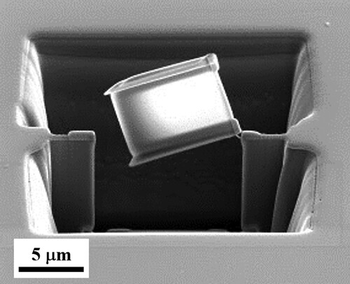
After the heat treatment, all of the samples were ground (with sandpapers) and polished (with Alumina powders) carefully. After the sample polishing, the microstructure of the samples was observed by using of the Leica DFC420 microscope (OM), the JEOL JSM-6380 scanning electron microscopy (SEM) and the FEI E.O TECNAI F20 G2 transmission electron microscopy (TEM) with an operating voltage of 120 kV which conducted at the Joint Center of High Valued Instruments, National Sun Yat-sen University. Before the TEM and HRTEM observation, the samples were prepared using the focus ion beam (FIB) milling, as shown in .
Figure 1. The TEM and HRTEM samples were prepared using the focus ion beam (FIB) milling.
2.4. Tensile test
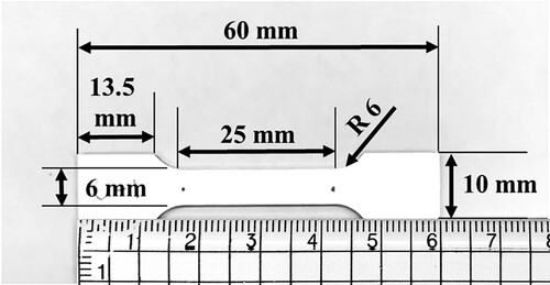
The 3D printed Al-Sc samples were prepared based on the ASTM E8 standard, as shown in . Before the tensile test, the samples were wire cut and ground carefully. To acquire the data for exploring the strengthening mechanism synergy, the tensile tests were performed by Instron 5582 universal testing machine at least five times at room temperature under a strain rate of 1 × 10⁻⁴ s−1. Meanwhile, no extensometer was used to obtain those tensile curves. The tensile test results and curves were corrected by the deduction of the elastic deformation of the testing machine itself, which was estimated from the results of tensile test specimens with known properties. Moreover, the elastic modulus was measured by the Hysitron TI Premier nanoindentation.
Figure 2. Schematic illustration of the tensile test sample of the 3D printed Scalmalloy. The size and geometry of the sample is referred to ASTM E8 standard.
3. Results and discussion
3.1. Mechanical properties
We notice that the relatively large standard deviation of mechanical properties may affect the assessment of the influence of the precipitate/microstructure on mechanical properties in our previous study (Kuo et al. Citation2021). Hence, to further explore the synergy of the strengthening mechanisms of the 3D printed Al-Sc samples with different heat-treatment processes (at 325oC for 4, 24 and 48 h), tensile tests were re-conducted on the heat-treated samples following the ASTM E8 standard. Before the tensile tests, all samples have been confirmed that the densification is over 99.85%, as shown in our previous study (Kuo et al. Citation2021). The stress–strain curves of the samples with/without heat treatment are shown in , and the mechanical properties are summarised in .
Figure 3. Tensile stress–strain curves of the as-built and heat-treated 3D printed Scalmalloy samples, and the arrows indicate yield stress.
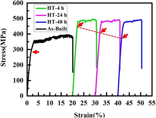
Table 1. Summary of tension mechanical properties of the 3D printed Scalmalloy samples with as-built and different heat-treated time at 325oC.
After heat treatment at 325oC for 4, 24 and 48 h, it shows a significantly increased in mechanical properties since the elimination of precipitate free zone plays an important role in improving the mechanical properties in scalmalloy. Which Young’s modulus increased from 72.1 GPa of the as-built sample to 99.2, 96.5 and 95.7 GPa after heat treatment at 325oC for 4, 24 and 48 h, respectively. On the other hand, yield stress increased from 286.9 MPa of the as-built sample to 471.8, 412.5 and 397.1 MPa after heat treatment at 325oC for 4, 24 and 48 h, respectively. Meanwhile, the elongation of all heat-treated samples is about 10% which can meet the requirements of most applications. Both the samples before and after tensile test were analysed by TEM in the following section to evaluate the microstructure evolution of Al3Sc precipitate with/without heat treatment.
3.2. Microstructure observations
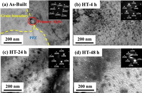
To identify the precipitate evolution according to the heat treatment parameter, all samples were examined by TEM, and the bright field TEM images and the corresponding selected area diffraction patterns (SADP) of the samples with/without heat-treatment are shown in . For the as-built sample, the Al3Sc precipitates were mainly found at the grain boundaries, and the precipitate free zone (PFZ) which the domain size over 300 nm exists due to the non-uniform distribution of Al3Sc, as shown in (a). The Al3Sc precipitated at the grain boundary forming a pinning effect that inhibits the growth of grains and leads to grain refinement during the 3D printing and heat-treatment processes. Since there are no precipitates in the precipitate free zone, there is no precipitation-strengthening effect in this region, which is the reason for the low yield stress of the as-built sample. On the other hand, after heat treatment for 4, 24 h or 48 h, no precipitation-free zone was observed in the samples due to the uniform distribution of precipitates, as shown in (b–d). According to the TEM results, the size of the precipitates in the as-built sample was 16.9 nm, and the size of the precipitates increased from 6.2, 11.4 to 14.2 nm with the heat treatment time from 4, 24 to 48 h, respectively. Meanwhile, the spacing of the precipitates increased from 11.7, 26.7 to 34.9 nm with the heat treatment time from 4, 24 to 48 h, respectively. Moreover, the volume fraction of Al3Sc precipitates increased from 0.048% (without heat treatment) to 0.139%, 0.354% and 0.364% after heat treatment for 4, 24 and 48 h, respectively.
Figure 4. TEM images and the corresponding selected area diffraction patterns (SADP) of (a) the as-built sample, (b) sample heat-treated at 325°C for 4 h, (c) sample heat-treated at 325°C for 24 h, and (d) sample heat-treated at 325°C for 48 h.
It is known that the α-Al and Al3Sc exhibit very similar lattice constants, which are 4.046 and 4.103 Å, respectively. Hence, the Al3Sc with a coherency could be precipitated with a critical radius of about 12.3 nm during the solidification (Iwamura and Miura Citation2004). With an addition above 3 wt% of Mg, the critical radius size could be increased to 40 nm due to the increased lattice constant of the α-Al (by 0.005 Å per 1 wt% Mg added) (Xu et al. Citation2019). This means that the small Al3Sc coherent phase may exist in the scalmalloy, and such a small coherent phase would also act as an obstacle during the dislocation sliding, thereby producing the Orowan strengthening effect. Hence, it is worth investigating the coherent phase and its interaction with dislocations ().
Table 2. Summary of Al3Sc precipitation size and volume fraction of the as-built and heat-treated Scalmalloy samples.
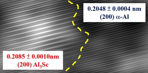
However, because the size of the coherent phase is less than 40 nm, the stress field is relatively small, so there is no Ashby-Brown strain characteristic. However, high-resolution TEM can be further used to observe its atomic arrangement, and the interplanar spacing of the α-Al and the Al3Sc can be calculated by using the inverse Fourier method, which is shown in . The interface of α-Al and Al3Sc can be observed (mark as yellow dashed line) and the interplanar spacing of Al3Sc and α-Al were 0.2085 and 0.2048nm, respectively, which were measured using Digital Micrograph.
Figure 5. HRTEM image on the interface of Al3Sc and α-Al. The interplanar spacing of Al3Sc and α-Al were 0.2085 and 0.2048 nm respectively, which were measured using Digital Micrograph.
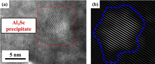
Moreover, in order to confirm the correlation between coherent phase and dislocation, more TEM specimens were taken near the fracture surface of the deformed samples. The interaction between the dislocations and the coherent phase was observed, as shown in and . For the as-built sample, it was found that the dislocation may slip through the coherent phase when the precipitate size is smaller than 4 nm, as shown in . On the other hand, for the heat-treated sample, it can block the dislocation and form the dislocation loop around the coherent phase when the size of the coherent phase is larger than 5 nm, as shown in .
Figure 6. The (a)HRTEM image and the (b)inverse Fourier transform image of the as-built sample after tensile test. It was observed the Al3Sc precipitate size was smaller than 4 nm, and two dislocations indicated by blue dashed lines pass through the precipitate.
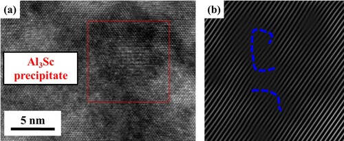
Figure 7. The (a) HRTEM image and the (b) inverse Fourier transform image of the deformed sample with heat-treated at 325°C for 4 h. It was observed that the Al3Sc precipitate size was larger than 5 nm and surrounded by a dislocation loop indicated by a blue dashed line.
3.3. Synergy of strengthening mechanism
According to the TEM observation, it is evidence that the coherent phase can also achieve the Orowan strengthening effect. Also, it is known that when the coefficient of thermal expansion (CTE) of the precipitates and the matrix is different during the deformation, the CTE mismatch strengthening effect between the precipitates and the matrix is superimposed on each other. Hence, it greatly increases the dislocation density and thereby forms dislocation entanglement, which impedes the movement of dislocation and increases the strength (Han et al. Citation2021). Moreover, it is known that the grain size strengthens the scalmalloy after parameter optimisation in our previous study (Kuo et al. Citation2019). Therefore, the correlation between the heat treatment parameter, microstructure and strength can be explained by the synergy of the Hall-Petch relationship, the Orowan strengthening mechanism, and the CTE mismatch strengthening mechanism. Hence, the theoretical yield stress can also be predicted by the following calculation:
First, the strengthening of the scalmalloy after heat treatment may contribute to the precipitate spacing, which the Orowan strengthening mechanism can predict the yield stress increase. According to Equationequation (1)(1)
(1) , the calculated theoretical yield stress increase caused by the Orowan strengthening mechanism of the samples heat-treated at 325oC for 4, 24 and 48 h is shown in and . According to , as the heat treatment time increases, the spacing between Al3Sc increases and thus reducing the effect of the Orowan strengthening mechanism. It noted that the coherent phases found in the heat-treated samples stopped the dislocation sliding according to the evidence shown in , and thus it can also promote the strength increase through the Orowan strengthening mechanism. On the other hand, for the as-built sample, dislocations can slide within the precipitate free zone due to the presence of PFZ in the as-built sample, and thus there was no significant yield stress increase due to the Orowan strengthening mechanism. Meanwhile, the small coherent phase (< 4 nm) found in the as-built sample also can not block the dislocation sliding according to the evidence shown in , thus the small-sized coherent phase does not affect the strength through the Orowan strengthening mechanism.
Figure 8. Relationship between yield stress increase caused by Orowan strengthening effect and the precipitate spacing of the samples heat-treated at 325°C for 4, 24 and 48 h.
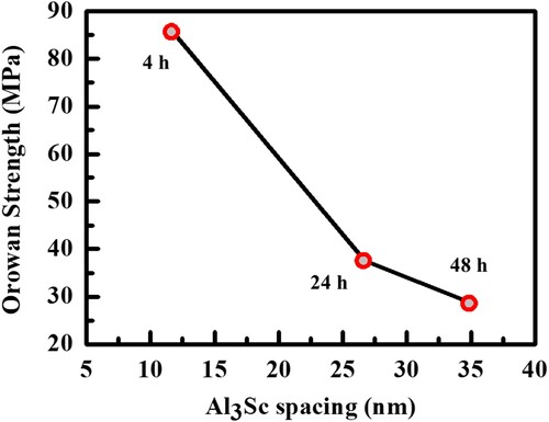
Table 3. The theoretical yield stress increase caused by Orowan strengthening mechanism of the samples heat-treated at 325°C for 4, 24 and 48 h.
Second, the strengthening of the scalmalloy after heat treatment may also contribute to the precipitate size, which the CTE mismatch strengthening mechanism can also predict the yield stress increase (Liu et al. Citation2021).
(2)
(2)
(3)
(3)
Where β represents the coefficient of dislocation strengthening, G is the shear modulus of the matrix, b is the Burgers vector, represents the dislocation density produced by the CTE mismatch, Δα represents the CTE difference between the Al3Sc precipitates and Al matrix, ΔT represents the difference between the processing and the test temperature, dp is the mean particle size and Vp is the volume fraction of Al3Sc precipitates. For aluminium alloys, the β = 1.25, Δα = 7.2 × 10⁻⁶ K−1 and ΔT = 310 K. Thus, the yield stress increase according to the CTE mismatch can be also calculated, as shown in and . Because the CTE mismatch strengthening effect is inversely proportional to precipitate size, the value of the yield stress increase decreases with increasing precipitate size or heat treatment time. On the other hand, since the precipitates were mainly found at the grain boundary of the as-built sample, such precipitates may not cause significant CTE mismatch effects.
Figure 9. Relationship between the yield stress increase caused by CTE strengthening mechanism and the precipitate size of the samples heat-treated at 325°C for 4, 24 and 48 h.
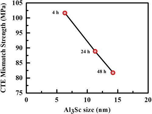
Table 4. The theoretical yield stress increase caused by CTE mismatch strengthening mechanism of the samples heat-treated at 325°C for 4, 24 and 48 h.
According to the results mentioned above, the synergy of strengthening mechanisms in the heat-treated scalmalloy can be described by the contributions of grain size strengthening (Hall-Petch relationship), precipitate spacing strengthening (Orowan strengthening) and precipitate size strengthening (CTE mismatch strengthening), shown in . First, during the LPBF process, the grain size can be refined by increasing the overlapping area through parameter optimisation, which results in a strength increase of about 18 MPa according to the Hall-Petch relationship. After heat treatment, the Al3Sc precipitated uniformly and thus eliminating the precipitate free zone, which increased the strength significantly. For the sample after heat treatment at 325oC for 4 h in , the small spacing between the precipitates and coherent phases contributes to the strength increase of about 86 MPa according to the Orowan strengthening mechanism. Meanwhile, the small precipitate size also improves the strength of 102 MPa according to the CTE mismatch strengthening mechanism. The precipitate size and spacing increased with increased heat treatment time, leading to a decrease in Orowan strengthening and CTE mismatch strengthening. The theoretical yield stress calculated by the synergy of strengthening mechanisms of all heat-treated samples is shown in . Compared to the experimental data, the difference between theoretical and experimental yield stress is less than 0.85%. This indicates that the yield stress prediction by the synergy of strengthening mechanisms perfectly matches the experimental yield stress, as shown in .
Figure 10. The synergy of the strengthening mechanisms which strengthened the 3D printed scalmalloy after heat treatment at 325oC for 4 h from 269 to 475 MPa.
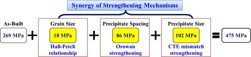
Figure 11. The theoretical and experimental relationship between yield stress and precipitate spacing/size ratio of samples heat-treated at 325°C for 4, 24 and 48 h.
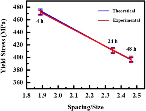
Table 5. The theoretical and experimental yield stress of all heat treated samples.
4. Conclusion
The synergy of strengthening mechanisms of 3D printed scalmalloy has been explored through the microstructure analysis of the as-built/heat-treated samples before/after deformation. According to the results and discussion, the following conclusions are drawn.
Not only >10 nm precipitates contribute to strengthening, but the 5–10 nm precipitates (or called coherent phase) also play an important role in the improvement of mechanical properties.
It is found that the critical size of the coherent phase that can cause the strengthening is >5 nm.
Through the observation of HRTEM, the precipitate size and spacing can be measured precisely, and thus the yield stress increment can be calculated through the Orowan strengthening mechanism and CTE mismatch strengthening mechanism.
The synergy of strengthening mechanisms, including the Hall-Petch relationship, Orowan strengthening mechanism and CTE mismatch strengthening mechanism, can predict the yield stress perfectly. The difference between theoretical and experimental yield stress is less than 0.85%.
Disclosure statement
No potential conflict of interest was reported by the author(s ).
Additional information
Funding
References
- Best, James P., Xavier Maeder, Johann Michler, and Adriaan B. Spierings. 2019. “Mechanical Anisotropy Investigated in TheComplex SLM-Processed Sc- and Zr-Modified Al–Mg Alloy Microstructure.” Advanced Engineering Materials 21 (3): 1801113. doi:10.1002/adem.201801113
- Cabrera-Correa, Leticia, Leandro González-Rovira, Juan de Dios López-Castro, Miguel Castillo-Rodríguez, and F. Javier Botana. 2023. “Effect of the Heat Treatment on the Mechanical Properties and Microstructure of Scalmalloy® Manufactured by Selective Laser Melting (SLM) Under Certified Conditions.” Materials Characterization 196: 112549. doi:10.1016/j.matchar.2022.112549
- Chen, S. Y., C. N. Kuo, Y. L. Su, J. C. Huang, Y. C. Wu, Y. H. Lin, Y. C. Chung, and C. H. Ng. 2018. “Microstructure and Fracture Properties of Open-Cell Porous Ti-6Al-4 V with High Porosity Fabricated by Electron Beam Melting.” Materials Characterization 138: 255–262. doi:10.1016/j.matchar.2018.02.016
- Choy, Sing Ying, Chen-Nan Sun, Wai Jack Sin, Kah Fai Leong, Pei-Chen Su, Jun Wei, and Pan Wang. 2021. “Superior Energy Absorption of Continuously Graded Microlattices by Electron Beam Additive Manufacturing.” Virtual and Physical Prototyping 16 (1): 14–28. doi:10.1080/17452759.2020.1868656
- Chua, C. K., and K. F. Leong. 2017. 3D Printing and Additive Manufacturing: Principles and Applications, 5th ed. Singapore: World Scientific.
- Chua, Chee Kai, Kah Fai Leong, and Chu Sing Lim. 2010. Rapid Prototyping: Principles and Applications. Singapore: World Scientific.
- Churyumov, A.Yu., A. V. Pozdniakov, A. S. Prosviryakov, I. S. Loginova, D. K. Daubarayte, D. K. Ryabov, V. A. Korolev, A. N. Solonin, M. D. Pavlov, and S. V. Valchuk. 2019. “Microstructure and Mechanical Properties of a Novel Selective Laser Melted Al-Mg Alloy with low Sc Content.” Materials Research Express 6 (12): 126595. doi:10.1088/2053-1591/ab5bea
- Gibson, Ian, David W Rosen, and Brent Stucker. 2010. Additive Manufacturing Technologies. New York: Springer.
- Han, Binghao, Shuiqing Liu, Xin Wang, Yingguang Liang, Yuhang Xia, and Chunxiang Cui. 2021. “Simultaneously Improving Strength and Ductility of Hybrid Al–Si Matrix Composite with Polyphasic and Multi-Scale Ceramic Particles.” Materials Science and Engineering: A 804: 140517. doi:10.1016/j.msea.2020.140517
- Iwamura, S., and Y. Miura. 2004. “Loss in Coherency and Coarsening Behavior of Al3Sc Precipitates.” Acta Materialia 52 (3): 591–600. doi:10.1016/j.actamat.2003.09.042
- Jägle, A. Eric., L. Lu, L. Wu, and D. Raabe. 2016. “Alloy Design for Additive Manufacturing”, 1–43.
- Jeyaprakash, N., Che-Hua Yang, and M. Saravana Kumar. 2022. “Influence of Coherent Intermetallic Nano-Precipitates on the Nano-Level Mechanical and Tribological Properties of the Laser-Powder bed Fused Scalmalloy.” Materials Characterization 193: 112269. doi:10.1016/j.matchar.2022.112269
- Koutny, Daniel, Daniel Skulina, Libor Pantělejev, David Paloušek, Blanka Lenczowski, Frank Palm, and Andreas Nick. 2018. “Processing of Al-Sc Aluminum Alloy Using SLM Technology.” Procedia CIRP 74: 44–48. doi:10.1016/j.procir.2018.08.027
- Kuo, C. N., C. K. Chua, P. C. Peng, Y. W. Chen, S. L. Sing, S. Huang, and Y. L. Su. 2019. “Microstructure Evolution and Mechanical Property Response via 3D Printing Parameter Development of Al–Sc Alloy.” Virtual and Physical Prototyping 15 (1): 120–129. doi:10.1080/17452759.2019.1698967
- Kuo, C. N., P. C. Peng, D. H. Liu, and C. Y. Chao. 2021. “Microstructure Evolution and Mechanical Property Response of 3D-Printed Scalmalloy with Different Heat-Treatment Times at 325oC.” Metals 11: 555. doi:10.3390/met11040555
- Li, Ruidi, Minbo Wang, Tiechui Yuan, Bo Song, Chao Chen, Kechao Zhou, and Peng Cao. 2017. “Selective Laser Melting of a Novel Sc and Zr Modified Al-6.2 Mg Alloy: Processing, Microstructure, and Properties.” Powder Technology 319: 117–128. doi:10.1016/j.powtec.2017.06.050
- Liu, Y. J., S. J. Li, H. L. Wang, W. T. Hou, Y. L. Hao, R. Yang, T. B. Sercombe, and L. C. Zhang. 2016. “Microstructure,: Defects and Mechanical Behavior of Beta-Type Titanium Porous Structures Manufactured by Electron Beam Melting and Selective Laser Melting.” Acta Materialia 113: 56–67. doi:10.1016/j.actamat.2016.04.029
- Liu, Shuiqing, Xin Wang, Qun Zu, Binghao Han, Xu Han, and Chunxiang Cui. 2021. “Significantly Improved Particle Strengthening of Al–Sc Alloy by High Sc Composition Design and Rapid Solidification.” Materials Science & Engineering A 800: 140304. doi:10.1016/j.msea.2020.140304
- Mikhaylovskaya, A. V., A. G. Mochugovskiy, V. S. Levchenko, N.Yu. Tabachkova, W. Mufalo, and V. K. Portnoy. 2018. “Precipitation Behavior of L12 Al3Zr Phase in Al-Mg-Zr Alloy.” Materials Characterization 139: 30–37. doi:10.1016/j.matchar.2018.02.030
- Murr, L. E. 2017. “Open-cellular Metal Implant Design and Fabrication for Biomechanical Compatibility with Bone Using Electron Beam Melting.” Journal of the Mechanical Behavior of Biomedical Materials 76: 164–177. doi:10.1016/j.jmbbm.2017.02.019
- Schimbäck, D., P. Mair, L. Kaserer, L. Perfler, F. Palm, G. Leichtfried, and S. Pogatscher. 2022. “An Improved Process Scan Strategy to Obtain High-Performance Fatigue Properties for Scalmalloy.” Materials & Design 224: 111410. doi:10.1016/j.matdes.2022.111410
- Schmidtke, K., F. Palm, A. Hawkins, and C. Emmelmann. 2011. “Process and Mechanical Properties: Applicability of a Scandium Modified Al-Alloy for Laser Additive Manufacturing.” Physics Procedia 12: 369–374. doi:10.1016/j.phpro.2011.03.047
- Sing, S. L., C. N. Kuo, C. T. Shih, C. C. Ho, and C. K. Chua. 2021. “Perspectives of Using Machine Learning in Laser Powder bed Fusion for Metal Additive Manufacturing.” Virtual and Physical Prototyping 16 (3): 372–386. doi:10.1080/17452759.2021.1944229
- Sing, S. L., and W. Y. Yeong. 2020. “Laser Powder bed Fusion for Metal Additive Manufacturing: Perspectives on Recent Developments.” Virtual and Physical Prototyping 15 (3): 359–370. doi:10.1080/17452759.2020.1779999
- Spierings, A. B., K. Dawson, T. Heeling, P. J. Uggowitzer, R. Schäublin, F. Palm, and K. Wegener. 2017a. “Microstructural Features of Sc- and Zr-Modified Al-Mg Alloys Processed by Selective Laser Melting.” Materials & Design 115: 52–63. doi:10.1016/j.matdes.2016.11.040
- Spierings, A. B., K. Dawson, K. Kern, F. Palm, and K. Wegener. 2017b. “SLM-processed Sc- and Zr- Modified Al-Mg Alloy: Mechanical Properties and Microstructural Effects of Heat Treatment.” Materials Science & Engineering A 701: 264–273. doi:10.1016/j.msea.2017.06.089
- Spierings, A. B., K. Dawson, P. J. Uggowitzer, and K. Wegener. 2018. “Influence of SLM Scan-Speed on Microstructure,: Precipitation of Al3Sc Particles and Mechanical Properties in Sc- and Zr-Modified Al-Mg Alloys.” Materials & Design 140: 134–143. doi:10.1016/j.matdes.2017.11.053
- Spierings, Adriaan B., Karl Dawson, Mark Voegtlin, Frank Palm, and Peter J. Uggowitzer. 2016. “Microstructure and Mechanical Properties of as-Processed Scandium-Modified Aluminium Using Selective Laser Melting.” CIRP Annals 65 (1): 213–216. doi:10.1016/j.cirp.2016.04.057
- Sudarmadji, N., J. Y. Tan, K. F. Leong, C. K. Chua, and Y. T. Loh. 2011. “Investigation of the Mechanical Properties and Porosity Relationships in Selective Laser-Sintered Polyhedral for Functionally Graded Scaffolds.” Acta Biomaterialia 7: 530–537. doi:10.1016/j.actbio.2010.09.024
- Tan, Joel Heang Kuan, Swee Leong Sing, and Wai Yee Yeong. 2020. “Microstructure Modelling for Metallic Additive Manufacturing: A Review.” Virtual and Physical Prototyping 15 (1): 87–105. doi:10.1080/17452759.2019.1677345
- Xu, Pian, Feng Jiang, Mengmeng Tong, Zhongqin Tang, Jingyu Jiang, Ning Yan, and Yongyi Peng. 2019. “Precipitation Characteristics and Morphological Transitions of Al3Sc Precipitates.” Journal of Alloys and Compounds 790: 509–516. doi:10.1016/j.jallcom.2019.03.256
- Zhang, Z., and D. L. Chen. 2006. “*Consideration of Orowan Strengthening Effect in Particulate-Reinforced Metal Matrix Nanocomposites: A Model for Predicting Their Yield Strength.” Scripta Materialia 54: 1321–1326. doi:10.1016/j.scriptamat.2005.12.017
- Zhao, Xiao Li, Shu Jun Li, Man Zhang, Yan Dong Liu, Timothy B. Sercombe, Shao Gang Wang, Yu Lin Hao, Rui Yang, and Lawrence E. Murr. 2016. “Comparison of the Microstructures and Mechanical Properties of Ti–6Al–4 V Fabricated by Selective Laser Melting and Electron Beam Melting.” Materials & Design 95: 21–31. doi:10.1016/j.matdes.2015.12.135