
 ?Mathematical formulae have been encoded as MathML and are displayed in this HTML version using MathJax in order to improve their display. Uncheck the box to turn MathJax off. This feature requires Javascript. Click on a formula to zoom.
ABSTRACT
Tantalum (Ta) has excellent prospects in the bone-implant field due to its satisfactory biocompatibility. Two novel Ta lattice structures were designed and printed by selective laser melting (SLM), including the imitation saddle surface (ISS) and the imitation arch bridge telescopic (IABT) structures. Quasi-static compression tests and finite element analysis were adopted to investigate the effects of design parameters on the mechanical properties, deformation modes, and energy absorption of lattice structures. Compared with the typical lattice structure body-centred cubic (BCC) structure, the ISS lattice structure had a higher yield-stress-to-elastic-modulus ratio, and the IABT lattice structure had higher energy absorption. The failure mode of the BCC and ISS lattice structures was shear band formation. The IABT lattice structure showed hierarchical deformation during compression and collapsed with vertical strut buckling. The results indicated that the ISS lattice is the most potential candidate for bone implant applications.
1. Introduction
Compared with bulk materials, lattice structures exhibit excellent performances, with high strength-to-weight ratios, energy absorption, and biocompatibility. In recent years, they have become a research focus in many fields, such as the aeronautics and astronautics, automotive, and biomedicine fields (Chen, Liang, et al. Citation2021). Lattice structures, as particular porous structures, have bright application prospects in bone implants because of their interconnected open pores and low elastic moduli, which can promote bone ingrowth and reduce stress shielding (Benedetti et al. Citation2021). Traditional porous materials have stochastic pore structures that limit the controllability of the cell size and shape. In contrast to stochastic scaffolds, a lattice material has a periodic geometric structure, making the mechanical properties and pore structure more controllable. Modifying the geometric design parameters of lattice structures can yield selected mechanical properties close to those of bone with a pore structure that is suitable for bone ingrowth (Chen, Liang, et al. Citation2021; Benedetti et al. Citation2021; du Plessis et al. Citation2018). The additive manufacturing (AM) process can fabricate lattice structures precisely and provide bone implant materials, structures, and function integration. The materials applied to bone implants are polymers (e.g. poly-ether-ether-ketone (PEEK) and polylactic acid (PLA)), metals (e.g. titanium), and ceramics (e.g. hydroxyapatite (HA)). The insufficient mechanical strength, limited osseointegration of PEEK (Ma et al. Citation2021), and lower fracture toughness of ceramics (Minagar et al. Citation2012) have impeded their further application. Many scholars are exploring composites of these materials to overcome the disadvantages of a single material (Jiang et al. Citation2022; Aihemaiti et al. Citation2022; Zheng, Zhao, et al. Citation2022).
Metal bone implants have been prevalently applied to load-bearing positions in the human body because of their high mechanical reliability (Depboylu et al. Citation2022; Mirkhalaf et al. Citation2022). Titanium alloys have good biocompatibility and mechanical properties when applied to spinal, hip, and knee implants (Aufa, Hassan, and Ismail Citation2022). However, the elastic modulus of Ti6Al4 V is 110 GPa (Wang et al. Citation2016), which is much higher than those of cortical and cancellous bone (15–20 GPa and 0.1–5 GPa, respectively) (Mirkhalaf et al. Citation2022; Aufa, Hassan, and Ismail Citation2022; Zhang, Chen, et al. Citation2022; McGregor et al. Citation2021; Liu et al. Citation2015). The incompatibility in the modulus between the implant and bone leads to most of the load being transferred to the implant. The absence of mechanotransduction on the bone will cause bone loss or resorption. This phenomenon is termed stress shielding, which leads to implant loosening and failure. The performance of porous Ti6Al4 V has been discussed in many previous studies. Research has mainly focused on improving its mechanical properties and osseointegration capabilities, including the fabrication of composite materials (Chen et al. Citation2022), structural optimisation (Zhang, Chen, et al. Citation2022), and surface modification (Lei et al. Citation2022).
Tantalum (Ta) is a transition metal with a high density (16.68 g/cm3), high melting point (3017 °C), and good ductility. A dense Ta2O5 film forms on the surface of Ta after oxidation, which has outstanding corrosion resistance (Wang, Ning, and Pei Citation2021). Compared with Ti alloys, Ta exhibits superior biocompatibility, corrosion resistance, and ductility (Bencharit et al. Citation2014; Piglionico et al. Citation2020; Li et al. Citation2013). Since the 1940s, Ta has been successfully employed in orthopaedics, such as hip, knee, artificial spine, shoulder, and dental implants (Minagar et al. Citation2012; Gao, Yang, et al. Citation2021; Fernández-Fairen et al. Citation2012; Bilandzic et al. Citation2020). However, its high density and low machinability have limited its further application. This bottleneck was overcome by powder bed fusion (PBF) additive manufacturing, such as the selective laser melting (SLM) and electron beam melting (EBM) processes. Unlike conventional methods, including chemical vapour deposition (CVD) and powder metallurgy (PM), the PBF process has the advantage of providing a satisfactory resolution, high energy input, and customised fabrication, making it an ideal candidate for manufacturing complex Ta lattice structures with fine feature sizes (Gao, Yang, et al. Citation2021; du Plessis et al. Citation2022). Wauthle et al. (Citation2015) manufactured a Ta lattice structure by the SLM process, which showed superior osteoconductive properties and fatigue strength. Chen, Yang et al. (Citation2021) designed Ta graded lattice structures. Fatigue testing showed that the Y-gradient structure exhibited longer fatigue lives as compared to uniform structures and Z-gradient. In vitro, the uniform structures demonstrated the best biocompatibility.
The mechanical properties of lattice structure materials significantly impact new bone ingrowth, osteointegration, and defective bone physical function substitution (Yang et al. Citation2020). For example, as an artificial vertebral body, suppose the elastic modulus of the lattice structure is much higher than that of the vertebra. In that case, stress shielding will be produced around the vertebral implant, which will hinder bone reconstruction and regeneration. If the yield strength of the lattice structure is much lower than that of the vertebra, the spinal load-bearing function cannot be substituted by the implant, which causes the collapse of the lattice structure. In addition, the lattice structure should have the capacity to resist impact loading for the restoration of functional spinal kinematics (Borem et al. Citation2019). Thus, the mechanical properties of Ta lattice structures should be tailored to higher yield strengths and lower elastic moduli to match the mechanical response of bone tissue and reduce stress shielding. Moreover, the energy absorption of lattice structures should be considered for medical devices with impact resistance applications.
There have been extensive previous studies on the mechanical properties of lattice structures, and most of them aimed to increase the elastic modulus and strength of the lattice (Yang, Chen, et al. Citation2022; Yang, Pan, et al. Citation2022; Prajapati et al. Citation2022). However, research on methods to reduce the elastic modulus without loss of mechanical strength is rare. Moreover, in contrast to Ti-6Al-4 V lattice structures, the discussions about the mechanical properties of Ta lattice structures fabricated by SLM have been limited. In this study, novel unit cells were designed by mimicking hyperbolic paraboloids and arch bridges to optimise the Ta lattice structures’ biomechanical properties and make them match those of human bone. The SLM process was adopted to produce various Ta lattice structure specimens with different unit cell types. The effects of the design parameters on the mechanical properties, deformation modes, and energy absorption of Ta lattice structures were investigated by a quasi-static compression test and finite element analysis.
2. Design and theory
Cellular materials are common in nature, such as wood, honeycombs, and sponges (Gibson and Ashby Citation1999). Imitation is an effective method for designing new lattice structures with desired mechanical properties (du Plessis et al. Citation2019; Isaac and Duddeck Citation2022). Inspired by hyperbolic paraboloids (also referred to as saddle surfaces) and arch bridges, the imitation saddle surface (ISS) and imitation arch bridge telescopic (IABT) unit cell structures were designed, respectively ().
Figure 1. Design of unit cells. Three types of as-designed unit cells, BCC, ISS, and IABT, inspired by Body-Centred Cubic Structure, Scotiabank Saddledome (hyperbolic paraboloids structure), and Zhaozhou Bridge, respectively.
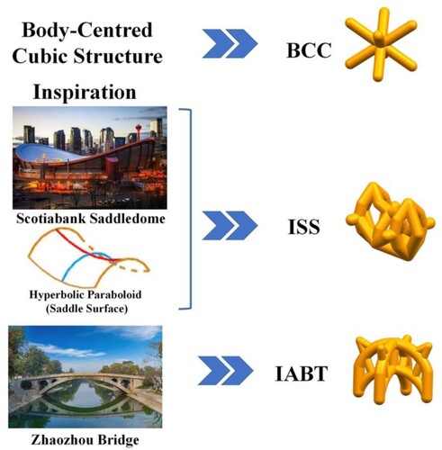
The Scotiabank Saddledome is located in Calgary, Alberta, Canada. Its top surface has a saddle surface design. The saddle surface structure provides powerful support for a building to withstand external loading because it can disperse the load effectively and balance the tension and compression ingeniously (J. Chilton Citation2010). Interconnected struts were adopted to achieve saddle surface imitation. This structure was expected to improve the lattice structure’s stability and load-bearing ability. Zhaozhou Bridge is a single-hole stone arch bridge with thousands of years of history that is located in the south of Zhao County, Shijiazhuang City, Hebei Province, China. The arch bridge can reduce the bending moment and is mainly subjected to compressive stresses under vertical loading. Bringing arch struts into the unit cell could improve the bearing capacity and stability of the lattice structure.
The body-centred cubic (BCC) lattice structure was designed and fabricated as a control specimen in this study. Many researchers have studied the mechanical properties of the BCC structure and its derived structures (such as BCCz) in detail (Bai, Gong, et al. Citation2021; Traxel et al. Citation2021; Li et al. Citation2021; Leary et al. Citation2018; Wang, Yang, et al. Citation2022). The mechanical properties and energy absorption of the novel lattice structures (ISS and IABT) and typical lattice structure (BCC) were compared, which we will discuss in detail in the next section.
The previous study indicated that a porosity exceeding 0.7 and a pore size ranging from 300 to 900 μm were beneficial for bone tissue ingrowth (Wang, Zhang, et al. Citation2022; Zhang et al. Citation2018). The design porosity of the lattice structure was approximately 0.8, and the average pore size was 850 μm. The cross section of the strut was circular. Its diameter and length are denoted as d and l, respectively. The lattice structure was constructed by unit cells in a periodic arrangement. The design dimensions of lattice structures were consistent with the compression specimen requirements in ISO 13314: 2011. The test specimen's design length, width, and height are denoted by L, W, and H, respectively. The design of unit cells and lattice structures was completed by three-dimensional drawing software. The design parameters are shown in .
Table 1. Design and print parameters of lattice structure.
According to the Maxwell criterion (Benedetti et al. Citation2021), the strut-based unit cell structure can be classified as bending dominated and stretching dominated. The relationship between the Maxwell number (m), strut number (s), and node number (n) can be expressed as follows:
(1)
(1) If m < 0, the lattice structure is classified as bending dominated. If m > 0, the lattice structure is classified as stretching dominated. The BCC, ISS, and IABT structures are bending-dominated lattice structures.
The Gibson–Ashby model (Benedetti et al. Citation2021; Gibson and Ashby Citation1999) is a classical model used to predict the mechanical properties of lattice structures. The elastic modulus (E*) and yield strength (σ*y) of the lattice structure can be calculated as follows:
(2)
(2) where ρ*/ρs is the relative density of the lattice structure, ρ*/ρs = 1−porosity; Es and σys are the elastic modulus and yield strength of the parent material, respectively; and C1, C2, m, and n are constants.
This model indicates that the elastic modulus and yield strength of the lattice structure are power functions of the relative density. The mechanical properties of lattice structures are controlled by the relative density. However, in addition to the relative density, other factors also have a significant influence on the mechanical properties of lattice structures. For example, Chua et al. (Citation2023) suggest that the effect of porosity on the yield strength of lattice structure might be more significant as compared to the strut geometry. However, the elastic modulus is more likely to be decided by the dimensions of the strut rather than the porosity.
The factors that have a significant influence on the mechanical properties of lattice structures can be summarised as follows:
Mechanical properties of the material, including the elastic modulus and yield strength (Chen, Liang, et al. Citation2021).;
Architecture of the lattice structure, including the unit cell structure (Wang, Meenashisundaram, et al. Citation2022), connection mode between unit cells (Bai, Xu, et al. Citation2021), orientations and positions of unit cells (Bhat, Kumar, and Jeng Citation2021), and arrangement of unit cells (Zhang, Song, et al. Citation2022);
Manufacturability, including geometric fidelity of lattice features, defects, and surface roughness (Wang, Chen, and Qiu Citation2021);
Building and loading directions (Wu and Yang Citation2021).
The lattice structure is composed of periodically arranged unit cells. The Euler–Bernoulli and Timoshenko beam theory is used to calculate the elastic moduli of unit cells with straight struts. The Castigliano theorem can be used to calculate the elastic moduli of unit cells with arch struts. The loading characteristic of different struts is shown in .
Figure 2. Stress characteristics of different strut types. Force analysis diagrams for vertical, inclined, and arch struts.
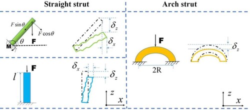
According to the Euler–Bernoulli beam theory, the displacement of strut in the Z direction can be expressed as follows:
(3)
(3) where A is the cross section of the strut; I is the moment of inertia, I = πd4/64.
Compared with the Euler–Bernoulli beam theory, the Timoshenko beam theory considers the shear deformation of the strut. Thus, the displacement of strut in the Z direction can be expressed as follows:
(4)
(4) where κ is shear coefficient factor; Gs is shear modulus of parent material.
According to the Castigliano theorem, the displacement of arch strut in the Z direction is shown as follows:
(5)
(5) The displacement of the unit cell in the Z direction (δUC,Z) is the summation of strut displacements in the Z direction. The strain of the unit cell can be calculated as:
(6)
(6)
where h is height of unit cell.
The elastic moduli of the unit cell are expressed by:
(7)
(7)
where σUC,Z is the stress of unit cell in Z direction.
In summary, the strut is the essential component of a strut-based lattice. Thus, the practical method of regulating the mechanical properties of strut-based lattices is to optimise the properties of the strut. Based on the Gibson–Ashby model (Eq. 2), Euler–Bernoulli beam theory, Timoshenko beam theory (Eq. (3–7) (Ahmadi et al. Citation2014; Timoshenko Citation1970), Maxwell criterion (Eq. 1), and previous studies, we believe that design parameters, such as the ratio of the strut diameter to length (d/l), the inclination angle of the strut (θ), and strut number (s), significantly influence the mechanical properties of strut-based lattice structures with identical materials.
For some unit cell structures with identical and symmetric struts, such as BCC, cubic, and diamond structures, their elastic moduli, plateau stresses, and Poisson's ratio values can be calculated by a theoretical method (Gharehbaghi, Sadeghzade, and Farrokhabadi Citation2022; Yu et al. Citation2022; Zheng, Li, et al. Citation2022; Zadpoor and Hedayati Citation2016; Hedayati et al. Citation2016). However, this is not easy for complex asymmetric structures, such as the ISS and IABT structures in this study. The effect of the design parameters on the mechanical properties of bending-dominated strut-based lattice structures can be characterised by the functions ƒ(x), as follows:
(8)
(8)
(9)
(9)
The Eq. (8–9) was used to design lattice structures with high yield-stress-to-elastic-modulus ratios. The design rules can be summarised as follows:
The proportion of slightly angled inclined struts (θ≤45°) should be increased in the whole unit cell structure.
The number of struts should be increased.
The ratio of the strut diameter to length should be increased.
A classic load-bearing structure should be simulated to improve the stability of the unit cell structure.
In this study, two novel lattice structures were designed according to those design rules: the ISS and IABT lattice structures. The effects of the design parameters on the mechanical properties, deformation mode, and energy absorption will be discussed in section 4.
3. Experimental and finite element methods
3.1. Materials and specimen fabrication
Pure Ta powder with spherical particle shapes provided by Xi'an Bright Laser Technologies Co., Ltd was used to fabricate porous Ta lattice structures. The particle sizes of D10, D50, and D90 were 18.371, 28.873, and 45.370 µm, respectively.
All the Ta lattice structures were printed by an SLM machine (BLT-S210) of Xi'an Bright Laser Technologies Co., Ltd. (Xi'an, Shanxi, China). The proper processing parameters, including laser power, scanning speed, laser spot size, layer thickness, and hatch distance, were adopted to fabricate dense specimens with good performance. The process parameters are listed in .
Table 2. SLM processing parameters.
The SLM machine (BLT-S210) is equipped with an Yb-fiber laser which has a maximum power of 500 W, the laser power is set to 240 W in this work. Layer thickness is one of the main parameters that affect the accuracy of the printed parts. Generally, the layer thickness of solid parts printed by SLM process is 0.1 mm. When printing the Ta lattice structure, because the rod diameter is small, the layer thickness is set to 0.03 mm to ensure accuracy. Each layer is printed in parallel scanning mode, and the angle between the scanning directions of adjacent layers is 67°, which enables homogenous energy input and reduces anisotropy. The specimens are fabricated in Argon protective atmosphere (O2% less than 100 ppm) to prevent oxidation.
3.2. Morphological analysis
The porosity of the specimen was scaled by dry weighing measurements, as follows:
(10)
(10) where Wa and Wt are the actual and theoretical weights of the specimen, respectively.
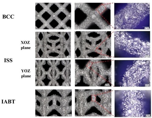
As shown in , the geometries of the fabricated lattice specimens were consistent with those of the designed structure. As shown by ultra-depth microscope images (), the printed specimens of all the lattice structures had no apparent defects except slight partially melted powder stuck on the surface.
Figure 3. Designed and fabricated Ta lattice structures. Lattice structure was constructed by unit cells in a periodic arrangement. Frontal view, top view, left side view, and overall view of BCC, ISS, and IABT designed and fabricated Ta lattice structures.
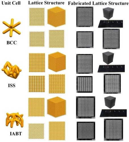
Figure 4. Digital microscope images of printed Ta lattice structures. Surface topography of BCC, ISS, and IABT printed Ta lattice structures under100, 150, and 500 magnifications of the digital microscope.
3.3. Compression testing
Quasi-static compressive tests of the specimens were conducted using a WANCE (ETM105D, 100 kN, WanCe Technologies Ltd., Shenzhen, China) mechanical testing machine at room temperature. Loading was along the building direction of the pieces. Based on ISO 13314: 2011, the loading rate was 1 mm/min. The deformation process of lattice structures during compression was recorded by a camera. Compression tests were stopped when the stress–strain curves showed densification characteristics of the specimens. Through force (F) and displacement (δ) data recorded by the machine, the stress–strain (σ*-ϵ) curves were obtained. σ* and ϵ are defined as follows:
(11)
(11) where A0 is the cross section of the lattice structure specimen, and H is the height of the lattice structure specimen. The elastic modulus (E*) was obtained by the slope of the elastic deformation region in the stress–strain curve, and the compressive 0.2% offset stress was defined as the yield strength (σ*y).
3.4. Finite element analysis
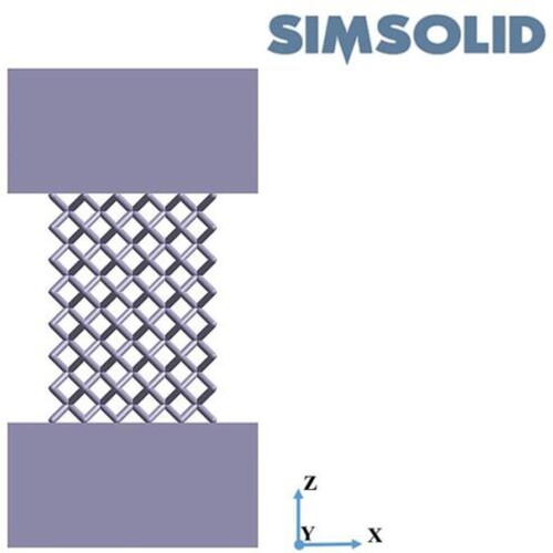
In this study, Altair SimSolid 2020 (Altair Engineering Inc, Troy, Michigan, USA) was used to analyse the quasi-static compression process of the lattice structure. Altair SimSolid eliminates geometry simplification and meshing, enabling the analysis of CAD assemblies without meshing. The density, elastic modulus, yield-stress, and Poisson's ratio of bulk Ta were 16.6 g/cm3, 186 GPa, 465 MPa, and 0.35, respectively, which were applied as material properties to the lattice structure model. The simulation model of lattice structure was constructed with 5 × 5 × 7 unit cells in a periodic arrangement. The digital microscope (VHX-6000, KEYENCE, Japan) was used to measure the diameters of the strut and pore of printed Ta lattice structure specimens. The deviation of the printed specimen from the design model was ignored in the simulation model because it is less than 10%. The lattice model was placed between the upper and lower platens, as shown in . The boundary condition was such that the upper platen moved down along the Z axis with a pre-set displacement, and the lower platen was immovable. The contact conditions were set as bonded. The solution settings were set as adapt for stress. The material non-linear was selected to conduct structural analysis.
Figure 5. Compression finite element model of Ta lattice structures. Lattice structure model was placed between upper and lower platens models, and the centre line of lattice structure model coincided with those of upper and lower platens models.
4. Results
4.1. Mechanical properties
The stress – strain curves of three lattice structure specimens under compression are shown in , and the experimental results are listed in . All the stress–strain curves of the specimens included three stages: linear elasticity, plastic deformation, and densification, which are consistent with the elastic–plastic cellular solids model in Gibson's research (Gibson and Ashby Citation1999). In the plastic deformation stage, the stress–strain curves of the BCC, ISS, and IABT lattice structures were smooth without stress oscillations, which could be attributed to the excellent ductility of Ta and the bending-dominated structures of the lattices. It was consistent with the mechanical behaviours of rhombic dodecahedron lattice Ta scaffolds concluded by Gao et al. (Citation2022). However, with the increase in the compressive strain, the IABT lattice structure showed multiple stress plateaus, and the plateau stress was enhanced layer by layer. It was apparent that the IABT had a strain hardening effect in the plastic deformation stage, in contrast to the BCC and ISS.
Figure 6. Stress–strain curves of Ta lattice structures. A stress-strain line graph of BCC, ISS, and IABT lattice structures plotting the relationship between stress and strain during quasi-static compressive tests.
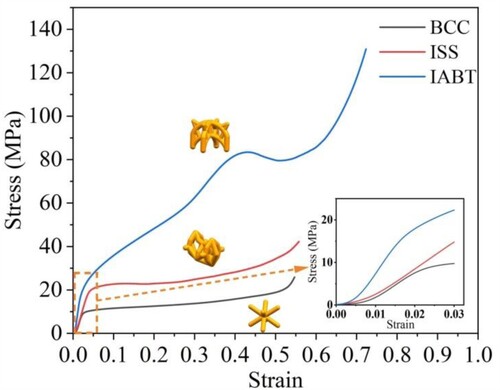
Table 3. Mechanical properties of Ta lattice structure/
As shown in , the yield strengths and elastic moduli of the BCC, ISS, and IABT lattice structures were significantly different, although they had similar relative densities. The IABT lattice had the highest yield strength and elastic modulus. This was due to the existence of vertical struts in the IABT lattice, which reinforced the strength of the structure. Compared with the BCC lattice, the ISS had a similar elastic modulus but much higher yield strength, almost twice that of the BCC lattice.
The yield-stress-to-elastic-modulus ratios (γ) of the lattice structure can quantitatively characterise the relationship between the yield strength and the elastic modulus:
(12)
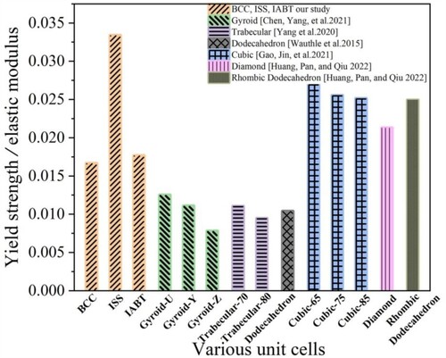
(12) In a bone implant, the higher the yield-stress-to-elastic-modulus ratios of the lattice structure are, the more it can fully play a load-bearing role while reducing stress shielding. The mechanical properties of the Ta lattice structure with various unit cells from the literature (Wauthle et al. Citation2015; Chen, Yang, et al. Citation2021; Yang et al. Citation2020; Huang, Pan, and Qiu Citation2022; Gao, Jin, et al. Citation2021) are listed in and displayed in . The ISS lattice that we designed had the highest yield-stress-to-elastic-modulus ratio.
Figure 7. Yield-stress-to-elastic-modulus ratios of Ta lattice structures. A histogram plotting yield-stress-to-elastic-modulus ratios of different Ta lattice structures. The ISS lattice had the highest yield-stress-to-elastic-modulus ratio.
4.2. Deformation behaviour
, , and show the deformation behaviours of the BCC, ISS, and IABT lattice structures with different strains during the compression tests. The BCC and ISS lattice structures collapsed due to inclined strut bending deformation and plastic hinges formed near the nodes. In the XOZ and YOZ planes, the BCC lattice structure experienced a transformation from a uniform deformation at first to ‘V’ shear band failure. The ISS lattice structure always maintained a uniform deformation in the XOZ plane. However, the ‘X’ shear band failure appeared in the YOZ plane with increased strain.
Figure 8. Deformation behaviour of body-centred cubic (BCC) lattice structure. Configuration of BCC lattice structure in the XOZ and YOZ plane at 5%, 10%, 20%, 30%, and 35% strains.
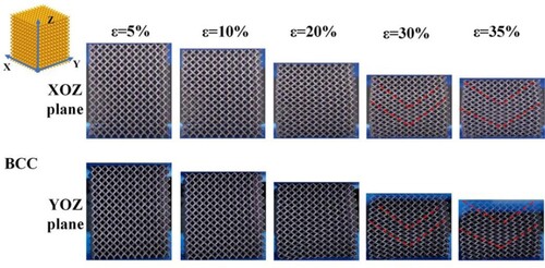
Figure 9. Deformation behaviour of imitation saddle surface (ISS) lattice structure. Configuration of ISS lattice structure in the XOZ and YOZ plane at 5%, 10%, 20%, 30%, and 35% strains.
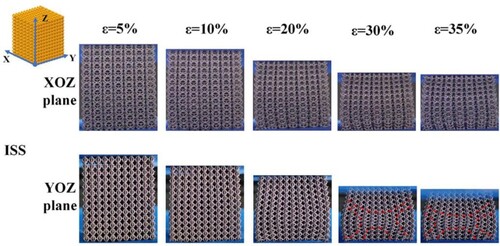
Figure 10. Deformation behaviour of imitation arch bridge telescopic (IABT) lattice structure. Configuration of IABT lattice structure in the XOZ and YOZ plane at 5%, 10%, 20%, 30%, and 35% strains.
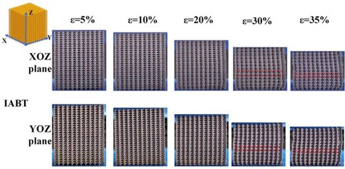
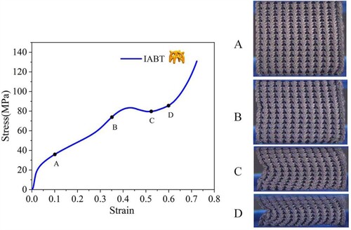
The deformation form of the IABT structure is depicted in , which included inclined strut bending and vertical strut buckling. During the deformation process, the inclined strut on top of the unit cell underwent bending deformation first (0.06 < ϵ < 0.29), then vertical strut axial deformation (0.29 < ϵ < 0.41), then vertical strut buckling (0.41 < ϵ < 0.52), and finally, lattice structure densification (ϵ > 0.62). These correspond to the multi-plateaus of the stress–strain curve.
Figure 11. Deformation behaviour of IABT lattice structure. Configuration of IABT lattice structure correspond to points A, B, C, and D on its stress-strain curve.
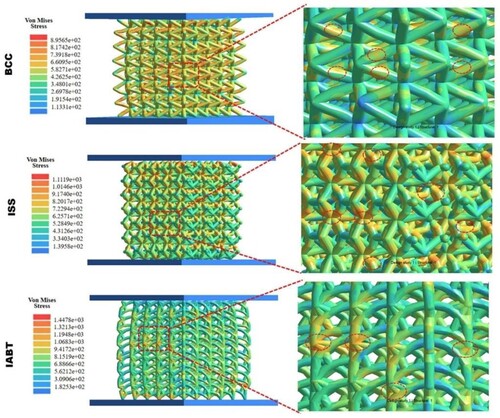
and show the deformation modes and von Mises stress distributions of different lattice structures from the finite element analysis. The deformation mode of the lattice structure from the simulation results was consistent with the experimental results. Shear bands appeared in the BCC and ISS lattices. As indicated by the red dashed circle in , in the initial plastic deformation stage, the von Mises stress was concentrated in the middle of the strut for the BCC lattice structure and focused at nodes for the ISS and IABT lattice structures.
Figure 12. Finite element (FE) result of lattice structures at 10% and 35% strains. Comparisons of BCC, ISS, and IABT lattice structure deformation behaviour between compression tests and FEA at 10% and 35% strains.
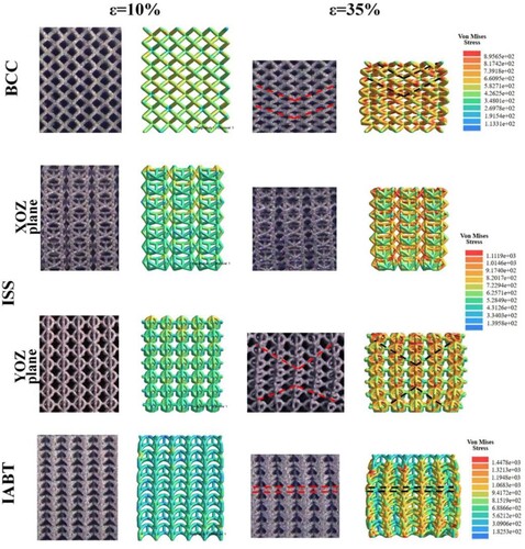
Figure 13. FE result of lattice structures at 20% strains. Location of stress concentration in BCC, ISS, and IABT lattice structure at 20% strains.
The deformation behaviours at the cross sections of the BCC, ISS, and IABT lattice structures after densification are shown in . The BCC, ISS, and IABT lattice structures had different degrees of expansion during compression. The expansion effect on the YOZ plane of the ISS lattice structure was more evident. This was because the horizontal restraint of the unit cell in the ISS lattice structure was insufficient, which made the orientations of the peripheral unit cells on the YOZ plane more prone to inclining, as indicated by the brown arrow in . No broken struts were found on the surfaces or cross sections of the ISS and BCC lattice structures. Due to global buckling, the IABT lattice swelled in one direction, similar to a ‘C’ shape. The connection nodes between the upper and lower unit cells on the outermost regions of the IABT lattice were broken, resulting from the node's weak tensile load resistance.
Figure 14. Deformation on cross sections of lattice structures after densification. Cross section configuration of BCC, ISS, and IABT lattice structure after densification.

4.3. Energy absorption
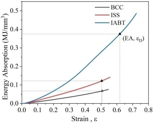
The energy absorbed by the lattice structure was the work performed by the force loaded on it. According to ISO 13314-2011, the energy absorption per unit volume is the area under the stress–strain curve from 0 up to the strain ϵ. This value can be calculated as follows and shown in :
(13)
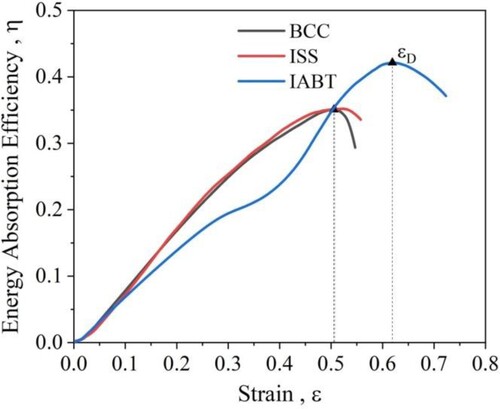
(13) The energy absorption capacity of a lattice structure is lost when densification begins. Thus, the densification strain ϵD is vital for the calculation of energy absorption. It can be defined as the peak point on the energy absorption efficiency–strain curves. The formula to calculate the energy absorption efficiency is shown as follows:
(14)
(14)
Figure 15. Energy absorption per unit volume (EA) curves of lattice structures. An EA-strain line graph of BCC, ISS, and IABT lattice structures plotting the relationship between EA and strain during quasi-static compressive tests.
The densification strains ϵD of lattice structures can be determined from . The plateau stress can be calculated as follows:
(15)
(15) where ϵy is the yield strain.
Figure 16. Energy absorption efficiency (EAE) curves of lattice structures. An EAE-strain line graph of BCC, ISS, and IABT lattice structures plotting the relationship between EAE and strain during quasi-static compressive tests.
The energy absorption per unit volume (EA) curves of three lattice structures are shown in , and the EA at densification strain ϵD values are listed in . The IABT lattice structure had the largest EA. It was 5.6 and 3.1 times as large as those of the BCC and ISS lattice structures, respectively, although they had similar relative densities.
Table 4. Energy absorption of lattice structures.
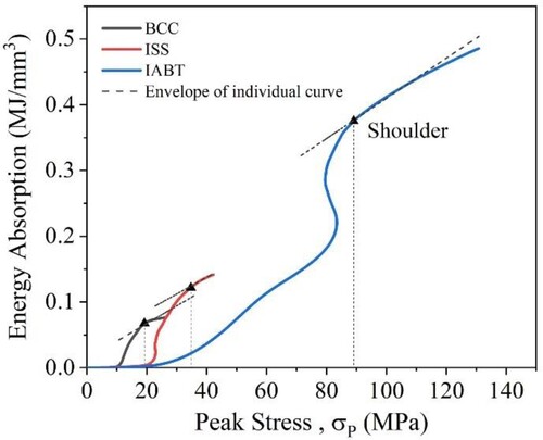
According to , the IABT lattice had the largest densification strain. The densification strains of the BCC and ISS lattices were similar. The peak stresses generated in the lattice structures of various types while absorbing energy were obtained from the shoulders on the energy curves in . The most appropriate lattice structure for energy absorption was the one that absorbed the most energy up to the maximum permissible stress. Thus, the peak stress is a threshold for choosing the optimal lattice structure applied for energy absorption. The IABT lattice structure absorbed more energy than the BCC and ISS lattice structures when the peak stress was 89 MPa.
Figure 17. Peak stresses of lattice structures. An EA-peak stress line graph of BCC, ISS, and IABT lattice structures plotting the relationship between EA and peak stress during quasi-static compressive tests.
5. Discussion
The compression test result showed that the ISS lattice structure had a higher yield-stress-to-elastic-modulus ratio than the traditional lattice structures, such as the BCC, trabecular, and dodecahedron structures. The ISS Ta lattice structure had a higher yield-stress and lower elastic modulus with the same relative density and material as compared to BCC lattice structure. This can be explained by the unique design parameters of the ISS lattice. The ISS unit cell structure contained abundant slightly inclined struts (θ ≤ 45°) and slightly angled struts represented 60% of the total number of struts. The axial forces on these struts could be ignored. According to Euler–Bernoulli and Timoshenko beam theory, these struts effectively reduced the elastic modulus of the lattice structure. Moreover, the orientations of the peripheral unit cells in the ISS lattice were more prone to inclining, which was beneficial for reducing the elastic modulus.
The number of struts in the ISS unit cell was 40, five times that of the BCC unit cell. The more struts there were, the more the structure could resist external reaction forces and higher yield-stresses. Bending-dominated strut-based lattice structures collapsed plastically when the bending moment in the struts reached the fully plastic moment. In line with Gibson–Ashby theory (Gibson and Ashby Citation1999), the plastic collapse stress of a lattice structure in the Z direction can be expressed as follows:
(16)
(16) where σys is the yield-stress of the parent material.
The average design length of the struts in the ISS lattice was 0.69 mm, which is shorter than that of the struts in the BCC lattice (1.56 mm). At a similar design diameter (0.39 mm for the BCC lattice and 0.34 mm for the ISS lattice), the ISS lattice had a higher ratio of strut diameter to length as compared to BCC lattice structure. In other words, compared with long struts, short struts had lower bending moments and higher plastic collapse stresses, which was the reason for the yield-stress of the ISS lattice being higher than that of the BCC lattice. The stress–strain curves in and show that the IABT exhibited a notable hardening effect in the plastic deformation stage. The cause of the strain hardening effect was mutual contact between the struts and the deformation-resistant capacity of the matrix material during compression.
The simulation results showed that the stress was focused in the middle of the strut and a plastic hinge formed near the node due to the BCC lattice having longer struts. However, in contrast to the BCC lattice, the plastic hinges of the ISS and IABT lattices formed at the nodes. The reinforcement capacity of the nodes enhanced their ability to resist the deformation of the lattice structure. Moreover, the ISS lattice was similar to the saddle surface, which could balance the tension and compression. Its uniform stress distribution further reinforced the strength of the lattice structure.
Maximising the load-bearing ability of bone implants and reducing stress shielding have become the main problems perplexing researchers. In our design, the BCC, ISS, and IABT lattice structures fabricated with Ta had similar elastic moduli (0.59-1.34 GPa) to that of cancellous bone (0.1-5 GPa). The ISS lattice structure had the highest yield-stress-to-elastic-modulus ratio, making it the most potential candidate for bone implant applications.
The deformation modes of a lattice structure are dominated by its strut type. The loading characteristic of various struts are shown in . During compression, the inclined struts underwent bending deformation when the moment exerted on the struts exceeded the fully plastic moment, creating plastic hinges. The vertical struts underwent axial compression deformation when the loading exceeded the yield strength. Based on the images in and the simulation results in and , we concluded the failure modes of lattice structures. ‘V’ shear bands penetrated the whole system, which led to the failure of the BCC lattice. In the YOZ plane, similar to the BCC lattice, the ISS lattice collapsed with ‘X’ shear bands. However, in the XOZ plane, the ISS lattice retained a uniform deformation mode during compression. The IABT lattice deformed layer by layer initially, followed by vertical strut axial deformation, and finally, it collapsed with vertical strut buckling.
The reason for the appearance of the shear band was that the maximum shear stress formed at 45° angles to the axial compression direction. The unit cells in this shear band deformed first. The asymmetric property of the ISS lattice structure prevented the formation of a shear band in the XOZ plane. The intensive struts and nodes in the ISS lattice structure led to more mutual contact and restraint, making the ISS lattice structure in the XOZ plane more prone to uniform deformation and having a higher plastic collapse stress than the BCC lattice structure. The swelling effect of the BCC and ISS lattice structures intensified the appearance of the shear band. Due to the deflection of the longitudinal axis of the unit cell from the loading direction, unit cells with inclined orientations preferentially filled the pores between the unit cells, resulting in the filling of the pores inside the unit cell being delayed. This is confirmed in . The horizontal struts in the ISS lattice structure were subjected to tensile stress during compression. These horizontal struts did not fracture after lattice structure densification, indicating the excellent compression toughness of Ta.
The hierarchical deformation of the IABT lattice structure was attributed to different types of struts. The inclined struts that linked up and down the unit cells were the weakest to resist deformation. Those struts bent first and led to layer-by-layer deformation of the lattice. The arch struts that linked the up and down unit cells were embedded with each other, providing a stable foundation for the axial deformation of the vertical struts. Soro et al. (Soro et al. Citation2022) indicate that horizontal or inclined struts could help the lattice structure resist buckling loads. The existence of vertical struts leads to the IABT lattice being prone to buckling. Once buckling deformation of the vertical strut occurred, the lattice structure lost stability. However, this misplacement layer provided more space for node displacement, leading to stress reduction in the stress–strain curves of the IABT lattice structure (0.41 <ϵ< 0.52). This can be further confirmed in .
The plateau stress and densification strain are critical factors for the energy absorption of the lattice structure (Xiao et al. Citation2022). As shown in , the IABT lattice structure had the maximum densification strain and plateau stress. The densification strains of the BCC and ISS lattices were similar, but the latter had a higher plateau stress. Due to the symmetry of the structure and uniform bending deformation of the inclined struts, the BCC lattice structure had good stability during compression. Thus, some researchers consider a long plateau on the stress–strain curve to be an indication of good energy absorption (Tancogne-Dejean and Mohr Citation2018). The stress–strain curves of lattice structures showed prominent characteristics of stress oscillations, resulting from it had brittle materials prone to fracture or vertical struts prone to buckling deformation. Compared with stress oscillations, a lattice structure with smooth stress variations during the plastic deformation stage would have higher energy absorption (Chen, Liang, et al. Citation2021; Gibson and Ashby Citation1999). However, in this study, owing to the excellent ductility of Ta and the bending-dominated structures of the lattices, stress oscillations were not found in the stress–strain curves of all ISS and IABT lattice structures. Thus, the energy absorption advantages of the BCC lattice structure were not apparent. Conversely, the energy absorption value of the BCC lattice structure was lower than that of the other lattice structures because its plateau stress was the lowest.
The multi-linear strain hardening effect of the IABT structure led to a higher plateau stress and densification strain than those of the BCC and ISS structures. The telescopic-arch strut designs provided sufficient stability for the IABT lattice structure during axial compression. The bearing functions of the vertical struts in the IABT lattice structure could be fully used during axial deformation due to the structural stability. This further improved the plateau stress and densification strain. Therefore, according to the deformation modes of the strut in the IABT lattice structure, we concluded that the novel design of the imitated telescopic arch bridge constructed a multi-layer energy absorption system that enhanced the energy absorption capabilities of the lattice structure.
The most appropriate lattice structure for energy absorption is the one that absorbed the most energy up to the maximum permissible stress (Gibson and Ashby Citation1999; Sharma and Hiremath Citation2022). As shown in , the BCC and ISS lattice structures ‘bottomed out’ as they were subjected to immense energy. For medical devices with impact resistance requiring sizeable kinetic energy absorption, the IABT lattice structure is the best choice.
This work aims to investigate the effect of different kinds of unit cell structures on the mechanical properties of lattice structures under the same process parameters. Therefore, the same SLM process parameters were used to fabricate all Ta lattice specimens. However, the SLM process parameters significantly affect printing quality and the mechanical properties of the lattice structure parts. Previous studies have indicated that identical specimens have different print qualities for different process parameters (Guo et al. Citation2020; Kuo et al. Citation2020; Levkulich et al. Citation2019). In the follow-up study, the influence of different process parameters on the accuracy, mechanical properties and microstructure of the lattice structure will be further researched.
In addition to the above, other factors also significantly influence the mechanical properties of lattice structures, such as microstructure, internal defects, heat treatment process, etc. We will also research these important factors in the future.
6. Conclusions
Inspired by saddle surface and arch bridge structures, novel lattice structures (ISS and IABT structures, respectively) were designed. Structure specimens were successfully fabricated by SLM. Quasi-static compression tests and finite element analysis were used to explore the Ta lattice structures’ mechanical properties, deformation mechanisms, and energy absorption characteristics. The central conclusions are as follows:
The BCC, ISS, and IABT lattice structures fabricated with Ta had similar elastic moduli (0.59–1.34 GPa) to that of cancellous bone (0.1–5 GPa). Compared with the BCC and IABT lattice structures, the ISS Ta lattice had the highest yield-stress-to-elastic-modulus ratio, making it the most potential candidate for bone implant applications. This can be attributed to the ISS lattice having more slightly angled inclined struts, greater total numbers of struts and nodes, and a higher ratio of the strut diameter to length.
The failure mode of the BCC lattice was ‘V’ shear band penetration of the whole system. The asymmetric property of the ISS lattice structure prevented the formation of shear bands in the XOZ plane, and the failure mode was ‘X’ shear band formation combined with uniform deformation. The IABT lattice deformed layer-by-layer initially, followed by vertical strut axial deformation, and finally, it collapsed with vertical strut buckling. The different stress characteristics of the struts (bending dominated or axial force dominated) in the lattice led to differences in the deformation modes.
The IABT lattice structure, due to the strain hardening effect and its sufficient stability, had the highest densification strain and plateau stress, which led to higher amounts of energy absorption than those of the BCC and ISS lattice structures.
Disclosure statement
No potential conflict of interest was reported by the author(s).
Additional information
Funding
References
- Ahmadi, S. M., G. Campoli, S. A. Yavari, B. Sajadi, R. Wauthle, J. Schrooten, H. Weinans, and A. A. Zadpoor. 2014. “Mechanical Behavior of Regular Open-Cell Porous Biomaterials Made of Diamond Lattice Unit Cells.” Journal of the Mechanical Behavior of Biomedical Materials 34: 106–115. doi:10.1016/j.jmbbm.2014.02.003.
- Aihemaiti, P., H. F. Jiang, W. Aiyiti, and A. Kasimu. 2022. “Optimization of 3D Printing Parameters of Biodegradable Polylactic Acid/Hydroxyapatite Composite Bone Plates.” International Journal of Bioprinting 8 (1), doi:10.18063/ijb.v8i1.490.
- Aufa, A. N., M. Z. Hassan, and Z. Ismail. 2022. “Recent Advances in Ti-6Al-4 V Additively Manufactured by Selective Laser Melting for Biomedical Implants: Prospect Development.” Journal of Alloys and Compounds 896. doi:10.1016/j.jallcom.2021.163072.
- Bai, L., C. Gong, X. H. Chen, J. Zheng, L. M. Xin, Y. Xiong, X. Y. Wu, M. J. Hu, K. Li, and Y. X. Sun. 2021. “Quasi-Static Compressive Responses and Fatigue Behaviour of Ti-6Al-4 V Graded Lattice Structures Fabricated by Laser Powder bed Fusion.” Materials & Design 210. doi:10.1016/j.matdes.2021.110110.
- Bai, L., Y. Xu, X. H. Chen, L. M. Xin, J. F. Zhang, K. Li, and Y. X. Sun. 2021. “Improved Mechanical Properties and Energy Absorption of Ti6Al4 V Laser Powder bed Fusion Lattice Structures Using Curving Lattice Struts.” Materials & Design 211. doi:10.1016/j.matdes.2021.110140.
- Bencharit, S., W. C. Byrd, S. Altarawneh, B. Hosseini, A. Leong, G. Reside, T. Morelli, and S. Offenbacher. 2014. “Development and Applications of Porous Tantalum Trabecular Metal-Enhanced Titanium Dental Implants.” Clinical Implant Dentistry and Related Research 16 (6): 817–826. doi:10.1111/cid.12059.
- Benedetti, M., A. du Plessis, R. O. Ritchie, M. Dallago, S. M. J. Razavi, and F. Berto. 2021. “Architected Cellular Materials: A Review on Their Mechanical Properties Towards Fatigue-Tolerant Design and Fabrication.” Materials Science & Engineering R-Reports 144. doi:10.1016/j.mser.2021.100606.
- Bhat, C., A. Kumar, and J. Y. Jeng. 2021. “Effect of Atomic Tessellations on Structural and Functional Properties of Additive Manufactured Lattice Structures.” Additive Manufacturing 47. doi:10.1016/j.addma.2021.102326.
- Bilandzic, M. D., C. Roos, A. Braun, and P. Jansen. 2020. “Development of a Radiopaque Dental Glass for Endodontic Laser Applications.” Journal of Materials Research and Technology-Jmr&T 9 (6): 13994–14001. doi:10.1016/j.jmrt.2020.09.091.
- Borem, R., A. Madeline, R. Vela, S. Gill, and J. Mercuri. 2019. “Multi-laminate Annulus Fibrosus Repair Scaffold with an Interlamellar Matrix Enhances Impact Resistance,: Prevents Herniation and Assists in Restoring Spinal Kinematics.” Journal of the Mechanical Behavior of Biomedical Materials 95: 41–52. doi:10.1016/j.jmbbm.2019.03.030.
- Chen, L. Y., S. X. Liang, Y. J. Liu, and L. C. Zhang. 2021. “Additive Manufacturing of Metallic Lattice Structures: Unconstrained Design, Accurate Fabrication,: Fascinated Performances, and Challenges.” Materials Science & Engineering R-Reports 146. doi:10.1016/j.mser.2021.100648.
- Chen, X., Y. L. Wu, H. L. Liu, Y. N. Wang, G. B. Zhao, Q. X. Zhang, F. Wang, and Y. X. Liu. 2022. “Mechanical Performance of PEEK-Ti6Al4 V Interpenetrating Phase Composites Fabricated by Powder bed Fusion and Vacuum Infiltration Targeting Large and Load-Bearing Implants.” Materials & Design 215. doi:10.1016/j.matdes.2022.110531.
- Chen, W. L., J. Z. Yang, H. Kong, M. Helou, D. C. Zhang, J. H. Zhao, W. T. Jia, Q. Liu, P. D. He, and X. P. Li. 2021. “Fatigue Behaviour and Biocompatibility of Additively Manufactured Bioactive Tantalum Graded Lattice Structures for Load-Bearing Orthopaedic Applications.” Materials Science & Engineering C-Materials for Biological Applications 130. doi:10.1016/j.msec.2021.112461.
- Chilton, J. 2010. “7-Tensile Structures -Textiles for Architecture and Design.” In Textiles, Polymers and Composites for Buildings, edited by Goeran Pohl, 229–257. Cambridge: Elsevier.
- Chua, Cherq, Swee Leong Sing, and C. K. Chua. 2023. “Characterisation of in-Situ Alloyed Titanium-Tantalum Lattice Structures by Laser Powder bed Fusion Using Finite Element Analysis.” Virtual and Physical Prototyping 18 (1): e2138463. doi:10.1080/17452759.2022.2138463.
- Depboylu, F. N., E. Yasa, O. Poyraz, J. Minguella-Canela, F. Korkusuz, and M. A. D. Lopez. 2022. “Titanium Based Bone Implants Production Using Laser Powder bed Fusion Technology.” Journal of Materials Research and Technology-Jmr&T 17: 1408–1426. doi:10.1016/j.jmrt.2022.01.087.
- du Plessis, A., C. Broeckhoven, I. Yadroitsava, I. Yadroitsev, C. H. Hands, R. Kunju, and D. Bhate. 2019. “Beautiful and Functional: A Review of Biomimetic Design in Additive Manufacturing.” Additive Manufacturing 27: 408–427. doi:10.1016/j.addma.2019.03.033.
- du Plessis, A., S. M. J. Razavi, M. Benedetti, S. Murchio, M. Leary, M. Watson, D. Bhate, and F. Berto. 2022. “Properties and Applications of Additively Manufactured Metallic Cellular Materials: A Review.” Progress in Materials Science 125. doi:10.1016/j.pmatsci.2021.100918.
- du Plessis, A., I. Yadroitsava, I. Yadroitsev, S. G. le Rouxa, and D. C. Blaine. 2018. “Numerical Comparison of Lattice Unit Cell Designs for Medical Implants by Additive Manufacturing.” Virtual and Physical Prototyping 13 (4): 266–281. doi:10.1080/17452759.2018.1491713.
- Fernández-Fairen, Mariano, Antonio Murcia, Ana Torres, Daniel Hernández-Vaquero, and Ann M. Menzie. 2012. “Is Anterior Cervical Fusion With a Porous Tantalum Implant a Cost-Effective Method to Treat Cervical Disc Disease With Radiculopathy?” Spine 37 (20): 1734–1741. doi:10.1097/BRS.0b013e318255a184.
- Gao, H. R., X. Jin, J. Z. Yang, D. C. Zhang, S. P. Zhang, F. Q. Zhang, and H. S. Chen. 2021. “Porous Structure and Compressive Failure Mechanism of Additively Manufactured Cubic-Lattice Tantalum Scaffolds.” Materials Today Advances 12. doi:10.1016/j.mtadv.2021.100183.
- Gao, H. R., J. Z. Yang, X. Jin, X. H. Qu, F. Q. Zhang, D. C. Zhang, H. S. Chen, et al. 2021. “Porous Tantalum Scaffolds: Fabrication, Structure, Properties, and Orthopedic Applications.” Materials & Design 210, doi:10.1016/j.matdes.2021.110095.
- Gao, H. R., J. Z. Yang, X. Jin, D. C. Zhang, S. P. Zhang, F. Q. Zhang, and H. S. Chen. 2022. “Static Compressive Behavior and Failure Mechanism of Tantalum Scaffolds with Optimized Periodic Lattice Fabricated by Laser-Based Additive Manufacturing.” 3d Printing and Additive Manufacturing, doi:10.1089/3dp.2021.0253.
- Gharehbaghi, H., M. Sadeghzade, and A. Farrokhabadi. 2022. “Introducing the new Lattice Structure Based on the Representative Element Double Octagonal Bipyramid.” Aerospace Science and Technology 121. doi:10.1016/j.ast.2022.107383.
- Gibson, L. J., and M. F. Ashby. 1999. Cellular Solids: Structure and Properties. Cambridge: Cambridge University Press.
- Guo, Chuan, Sheng Li, Shi Shi, Xinggang Li, Xiaogang Hu, Qiang Zhu, and R. Mark Ward. 2020. “Effect of Processing Parameters on Surface Roughness, Porosity and Cracking of as-Built IN738LC Parts Fabricated by Laser Powder bed Fusion.” Journal of Materials Processing Technology 285: 116788. doi:10.1016/j.jmatprotec.2020.116788.
- Hedayati, R., M. Sadighi, M. Mohammadi-Aghdam, and A. A. Zadpoor. 2016. “Mechanical Properties of Regular Porous Biomaterials Made from Truncated Cube Repeating Unit Cells: Analytical Solutions and Computational Models.” Materials Science & Engineering C-Materials for Biological Applications 60: 163–183. doi:10.1016/j.msec.2015.11.001.
- Huang, G., S. T. Pan, and J. X. Qiu. 2022. “The Osteogenic Effects of Porous Tantalum and Titanium Alloy Scaffolds with Different Unit Cell Structure.” Colloids and Surfaces B-Biointerfaces 210. doi:10.1016/j.colsurfb.2021.112229.
- Isaac, C. W., and F. Duddeck. 2022. “Current Trends in Additively Manufactured (3D Printed) Energy Absorbing Structures for Crashworthiness Application - a Review.” Virtual and Physical Prototyping, doi:10.1080/17452759.2022.2074698.
- Jiang, H. F., P. Aihemaiti, W. Aiyiti, and A. Kasimu. 2022. “Study Of the Compression Behaviours of 3D-Printed PEEK/CFR-PEEK Sandwich Composite Structures.” Virtual and Physical Prototyping 17 (2): 138–155. doi:10.1080/17452759.2021.2014636.
- Kuo, C. N., C. K. Chua, P. C. Peng, Y. W. Chen, S. L. Sing, S. Huang, and Y. L. Su. 2020. “Microstructure Evolution and Mechanical Property Response via 3D Printing Parameter Development of Al–Sc Alloy.” Virtual and Physical Prototyping 15 (1): 120–129. doi:10.1080/17452759.2019.1698967.
- Leary, M., M. Mazur, H. Williams, E. Yang, A. Alghamdi, B. Lozanovski, X. Z. Zhang, et al. 2018. “Inconel 625 Lattice Structures Manufactured by Selective Laser Melting (SLM): Mechanical Properties, Deformation and Failure Modes.” Materials & Design 157: 179–199. doi:10.1016/j.matdes.2018.06.010.
- Lei, P. F., H. Qian, T. M. Zhang, T. Lei, Y. H. Hu, C. Chen, and K. C. Zhou. 2022. “Porous Tantalum Structure Integrated on Ti6Al4 V Base by Laser Powder Bed Fusion for Enhanced Bony-Ingrowth Implants: In Vitro and in Vivo Validation.” Bioactive Materials 7: 3–13. doi:10.1016/j.bioactmat.2021.05.025.
- Levkulich, N. C., S. L. Semiatin, J. E. Gockel, J. R. Middendorf, A. T. DeWald, and N. W. Klingbeil. 2019. “The Effect of Process Parameters on Residual Stress Evolution and Distortion in the Laser Powder bed Fusion of Ti-6Al-4 V.” Additive Manufacturing 28: 475–484. doi:10.1016/j.addma.2019.05.015.
- Li, P. Y., Y. E. Ma, W. B. Sun, X. D. Qian, W. H. Zhang, and Z. H. Wang. 2021. “Fracture and Failure Behavior of Additive Manufactured Ti6Al4 V Lattice Structures Under Compressive Load.” Engineering Fracture Mechanics 244. doi:10.1016/j.engfracmech.2021.107537.
- Li, X., L. Wang, X. M. Yu, Y. F. Feng, C. T. Wang, K. Yang, and D. Su. 2013. “Tantalum Coating on Porous Ti6Al4 V Scaffold Using Chemical Vapor Deposition and Preliminary Biological Evaluation.” Materials Science & Engineering C-Materials for Biological Applications 33 (5): 2987–2994. doi:10.1016/j.msec.2013.03.027.
- Liu, Y. D., C. Y. Bao, D. Wismeijer, and G. Wu. 2015. “The Physicochemical/Biological Properties of Porous Tantalum and the Potential Surface Modification Techniques to Improve its Clinical Application in Dental Implantology.” Materials Science & Engineering C-Materials for Biological Applications 49: 323–329. doi:10.1016/j.msec.2015.01.007.
- Ma, Hongyun, Jingyuan Zhou AngxiuSuonan, Qiling Yuan, Liang Liu, Xiaoming Zhao, Xiaoxiao Lou, Chuncheng Yang, Dichen Li, and Yin-gang Zhang. 2021. “PEEK (Polyether-Ether-Ketone) and its Composite Materials in Orthopedic Implantation.” Arabian Journal of Chemistry 14 (3): 102977. doi:10.1016/j.arabjc.2020.102977.
- McGregor, M., S. Patel, S. McLachlin, and M. Vlasea. 2021. “Architectural Bone Parameters and the Relationship to Titanium Lattice Design for Powder bed Fusion Additive Manufacturing.” Additive Manufacturing 47. doi:10.1016/j.addma.2021.102273.
- Minagar, S., C. C. Berndt, J. Wang, E. Ivanova, and C. Wen. 2012. “A Review of the Application of Anodization for the Fabrication of Nanotubes on Metal Implant Surfaces.” Acta Biomaterialia 8 (8): 2875–2888. doi:10.1016/j.actbio.2012.04.005.
- Mirkhalaf, Mohammad, Yinghui Men, Rui Wang, Young No, and Hala Zreiqat. 2022. “Personalized 3D Printed Bone Scaffolds: A Review.” Acta Biomaterialia, doi:10.1016/j.actbio.2022.04.014.
- Piglionico, S., J. Bousquet, N. Fatima, M. Renaud, P. Y. Collart-Dutilleul, and P. Bousquet. 2020. “Porous Tantalum vs. Titanium Implants: Enhanced Mineralized Matrix Formation After Stem Cells Proliferation and Differentiation.” Journal of Clinical Medicine 9: 11. doi:10.3390/jcm9113657.
- Prajapati, Mayur Jiyalal, Ajeet Kumar, Shang-Chih Lin, and Jeng-Ywan Jeng. 2022. “Multi-material Additive Manufacturing with Lightweight Closed-Cell Foam-Filled Lattice Structures for Enhanced Mechanical and Functional Properties.” Additive Manufacturing 54: 102766. doi:10.1016/j.addma.2022.102766.
- Sharma, D., and S. S. Hiremath. 2022. “Bio-inspired Repeatable Lattice Structures for Energy Absorption: Experimental and Finite Element Study.” Composite Structures 283. doi:10.1016/j.compstruct.2021.115102.
- Soro, Nicolas, Erin G. Brodie, Abdalla Abdal-hay, Aya Q. Alali, Damon Kent, and Matthew S. Dargusch. 2022. “Additive Manufacturing of Biomimetic Titanium-Tantalum Lattices for Biomedical Implant Applications.” Materials & Design 218: 110688. doi:10.1016/j.matdes.2022.110688.
- Tancogne-Dejean, T., and D. Mohr. 2018. “Stiffness and Specific Energy Absorption of Additively-Manufactured Metallic BCC Metamaterials Composed of Tapered Beams.” International Journal of Mechanical Sciences 141: 101–116. doi:10.1016/j.ijmecsci.2018.03.027.
- Timoshenko, S. P. 1970. Theory of Elastic Stability. New York: Tata McGraw-Hill Education.
- Traxel, K. D., C. Groden, J. Valladares, A. Bandyopadhyay, and W. M. Keck. 2021. “Mechanical Properties of Additively Manufactured Variable Lattice Structures of Ti6Al4 V.” Materials Science and Engineering a-Structural Materials Properties Microstructure and Processing 809. doi:10.1016/j.msea.2021.140925.
- Wang, G. Q., X. Chen, and C. L. Qiu. 2021. “On the Macro- and Micro-Deformation Mechanisms of Selectively Laser Melted Damage Tolerant Metallic Lattice Structures.” Journal of Alloys and Compounds 852. doi:10.1016/j.jallcom.2020.156985.
- Wang, Niyou, Ganesh Kumar Meenashisundaram, Deepika Kandilya, Jerry Ying HsiFuh, S. ThameemDheen, and A. Senthil Kumar. 2022. “A Biomechanical Evaluation on Cubic, Octet, and TPMS Gyroid Ti6Al4 V Lattice Structures Fabricated by Selective Laser Melting and the Effects of Their Debris on Human Osteoblast-Like Cells.” Biomaterials Advances 137: 212829. doi:10.1016/j.bioadv.2022.212829.
- Wang, X., B. Y. Ning, and X. B. Pei. 2021. “Tantalum and its Derivatives in Orthopedic and Dental Implants: Osteogenesis and Antibacterial Properties.” Colloids and Surfaces B-Biointerfaces 208. doi:10.1016/j.colsurfb.2021.112055.
- Wang, Xiaojian, Shanqing Xu, Shiwei Zhou, Wei Xu, Martin Leary, Peter Choong, M. Qian, Milan Brandt, and Yi Min Xie. 2016. “Topological Design and Additive Manufacturing of Porous Metals for Bone Scaffolds and Orthopaedic Implants: A Review.” Biomaterials 83: 127–141. doi:10.1016/j.biomaterials.2016.01.012.
- Wang, P., F. Yang, G. X. Lu, Y. J. Bian, S. Y. Zhang, B. L. Zheng, and H. L. Fan. 2022. “Anisotropic Compression Behaviors of bio-Inspired Modified Body-Centered Cubic Lattices Validated by Additive Manufacturing.” Composites Part B-Engineering 234. doi:10.1016/j.compositesb.2022.109724.
- Wang, Zihang, Mei Zhang, Zhewen Liu, Yilong Wang, Wenying Dong, Shanshan Zhao, and Dahui Sun. 2022. “Biomimetic Design Strategy of Complex Porous Structure Based on 3D Printing Ti-6Al-4 V Scaffolds for Enhanced Osseointegration.” Materials & Design 218: 110721. doi:10.1016/j.matdes.2022.110721.
- Wauthle, R., J. van der Stok, S. A. Yavari, J. Van Humbeeck, J. P. Kruth, A. A. Zadpoor, H. Weinans, M. Mulier, and J. Schrooten. 2015. “Additively Manufactured Porous Tantalum Implants.” Acta Biomaterialia 14: 217–225. doi:10.1016/j.actbio.2014.12.003.
- Wu, Y., and L. Yang. 2021. “Modeling and Analysis of Material Anisotropy-Topology Effects of 3D Cellular Structures Fabricated by Powder bed Fusion Additive Manufacturing.” International Journal of Mechanical Sciences 197. doi:10.1016/j.ijmecsci.2021.106325.
- Xiao, L. J., X. Xu, G. Z. Feng, S. Li, W. D. Song, and Z. X. Jiang. 2022. “Compressive Performance and Energy Absorption of Additively Manufactured Metallic Hybrid Lattice Structures.” International Journal of Mechanical Sciences 219. doi:10.1016/j.ijmecsci.2022.107093.
- Yang, Jianxing, Xiaohong Chen, Yuanxi Sun, Junfang Zhang, Chen Feng, Yanmiao Wang, Ke Wang, and Long Bai. 2022. “Compressive Properties of Bidirectionally Graded Lattice Structures.” Materials & Design 218: 110683. doi:10.1016/j.matdes.2022.110683.
- Yang, J. Z., X. Jin, H. R. Gao, D. C. Zhang, H. S. Chen, S. P. Zhang, and X. P. Li. 2020. “Additive Manufacturing of Trabecular Tantalum Scaffolds by Laser Powder bed Fusion: Mechanical Property Evaluation and Porous Structure Characterization.” Materials Characterization 170. doi:10.1016/j.matchar.2020.110694.
- Yang, Ding, Chen Pan, Yong Zhou, and Yafeng Han. 2022. “Optimized Design and Additive Manufacture of Double-Sided Metal Mirror with Self-Supporting Lattice Structure.” Materials & Design 219: 110759. doi:10.1016/j.matdes.2022.110759.
- Yu, G. J., X. Li, L. S. Dai, L. J. Xiao, and W. D. Song. 2022. “Compressive Properties of Imperfect Ti-6Al-4 V Lattice Structure Fabricated by Electron Beam Powder bed Fusion Under Static and Dynamic Loadings.” Additive Manufacturing 49. doi:10.1016/j.addma.2021.102497.
- Zadpoor, A. A., and R. Hedayati. 2016. “Analytical Relationships for Prediction of the Mechanical Properties of Additively Manufactured Porous Biomaterials.” Journal of Biomedical Materials Research Part A 104 (12): 3164–3174. doi:10.1002/jbm.a.35855.
- Zhang, Junfang, Xiaohong Chen, Yuanxi Sun, Jianxing Yang, Rui Chen, Yan Xiong, Wensheng Hou, and Long Bai. 2022. “Design of a Biomimetic Graded TPMS Scaffold with Quantitatively Adjustable Pore Size.” Materials & Design 218: 110665. doi:10.1016/j.matdes.2022.110665.
- Zhang, B. Q., X. Pei, C. C. Zhou, Y. J. Fan, Q. Jiang, A. Ronca, U. D'Amora, et al. 2018. “The Biomimetic Design and 3D Printing of Customized Mechanical Properties Porous Ti6Al4 V Scaffold for Load-Bearing Bone Reconstruction.” Materials & Design 152: 30–39. doi:10.1016/j.matdes.2018.04.065.
- Zhang, L., B. Song, S. K. Choi, Y. G. Yao, and Y. S. Shi. 2022. “Anisotropy-inspired: Simulation-Guided Design and 3D Printing of Microlattice Metamaterials with Tailored Mechanical-Transport Performances.” Composites Part B-Engineering 236. doi:10.1016/j.compositesb.2022.109837.
- Zheng, T. T., S. Li, G. Wang, Y. C. Hu, and C. Q. Zhao. 2022. “Mechanical and Energy Absorption Properties of the Composite XX-Type Lattice Sandwich Structure.” European Journal of Mechanics a-Solids 91. doi:10.1016/j.euromechsol.2021.104410.
- Zheng, Jibao, Huiyu Zhao, Zhicong Ouyang, Xinying Zhou, Jianfeng Kang, Chuncheng Yang, Changning Sun, et al. 2022. “Additively-manufactured PEEK/HA Porous Scaffolds with Excellent Osteogenesis for Bone Tissue Repairing.” Composites Part B: Engineering 232: 109508. doi:10.1016/j.compositesb.2021.109508.