
ABSTRACT
A Ti/β-TCP composite porous scaffold with a hierarchical pore structure composed of 3D printed interconnected macroscopic pores and sintered microscopic pores was prepared by direct ink writing (DIW) 3D printing technology. This method can control the extrusion of composite ink at room temperature and produce a 3D scaffold using layer-by-layer deposition. We studied the effects of the β-TCP powder particle size, β-TCP/Ti powder ratio and solid loading on the rheological properties of the ink and optimised the DIW printing process parameters. After sintering, the compressive strength and elastic modulus of the composite scaffold reached 45 MPa and 1 GPa, which is close to the strength of human cancellous bone. The cell culture experiment confirmed that the composite scaffold had better biological properties than the pure titanium scaffold. The composite scaffold has satisfactory mechanical and biological properties, meeting the requirements for orthopaedic implants.
1. Introduction
With the acceleration of population aging, the quickening of the pace of life and the deterioration of the urban environment, tens of millions of patients with bone defects caused by severe trauma, tumour resection or congenital diseases must be treated every year. Such a high number of patients greatly impacts patient wellness and thus has become a significant social problem (Gao et al. Citation2017; Montazerolghaem et al. Citation2016; Wang and Yeung Citation2017; Yang et al. Citation2020). Currently, artificial implants (generally metal implants) are used to repair and rebuild bone defects.
Titanium (alloy), with great mechanical strength and biocompatibility, is a common material for metal implants in clinical use. However, because it is biologically inert, titanium has a poor capability of bone conduction after implantation and is difficult to form synostosis with the surrounding bone tissues. Its long-term implantation is likely to lead to osteolysis and implant loosening and failure. The bioactivity of titanium (alloy) implants can be improved by depositing a layer of bioactive ceramic coating (e.g. β-tricalcium phosphate and hydroxyapatite) through plasma spraying (Hung et al. Citation2013; Xia et al. Citation2018), hydrometallurgy sedimentation (Shin et al. Citation2015) and laser deposition (Eraković et al. Citation2014) because of the excellent biocompatibility and osteoconductivity of the coating due to the similarity of its composition to that of the inorganic mineral phase of bones (Zhang et al. Citation2007; Montazerian et al. Citation2022). However, due to the poor bonding strength between the titanium (alloy) matrix and the ceramic coating and the brittleness of the coating itself, the coating may peel off after long-term implantation, resulting in the loosening of the implant (Surmenev, Surmeneva, and Ivanova Citation2014). Therefore, noncoated titanium (alloy)/bioceramic composite materials are becoming a hot research topic.
Combining titanium (alloy) with bioceramic to create a titanium (alloy)/bioceramic composite bone repair scaffold with both high mechanical strength and bioactivity is beneficial for the integration of the implants with the bone and for the improvement in the stability of long-term implantation. The traditional methods for the fabrication of porous titanium (alloy)/bioceramic composite materials include metal injection moulding and powder sintering (Thian et al. Citation2002b, Citation2002a; Omran et al. Citation2015). The main principle is to mix titanium (alloy) powder with the bioceramic powder and form a green part by pressing or injection moulding prior to sintering to obtain mechanical strength. Most of the structures prepared by these traditional methods are solid structures. The structures fabricated using space-holders have random pore structures that prevents the control of the structural (including the pore size, shape and connectivity) and mechanical properties (Chen et al. Citation2017).
Implants for bone defect repair must have macroscopic porous structures to provide channels for bone ingrowth. In addition, the mechanical properties of the scaffold can be adjusted through the pore size and porosity to obtain an appropriate elastic modulus and strength for bone implantation (Laurencin, Khan, and El-Amin Citation2006; Taniguchi et al. Citation2016). 3D printing is a digitally driven, layer-by-layer manufacturing technology with outstanding advantages compared to the traditional manufacturing methods. 3D printing can manufacture customised porous structures with a complicated appearance and the desired physical, mechanical and biological properties.
Recently, selective laser melting (SLM), laser engineered net shaping (LENS) and electron beam melting (EBM) have become the main methods for 3D printing of titanium (alloy) (Zhang and Chen Citation2019; Majumdar et al. Citation2018; Lewis and Shah Citation2016; Munir, Li, and Wen Citation2017) and titanium-based composite materials (Hu et al. Citation2018; Attar et al. Citation2014; Diao and Zhang Citation2015). Nevertheless, these methods are only applicable to single metals and cannot be used with multiple materials. Thus, the manufacturing of metal/ceramic composite porous scaffolds is quite challenging for several reasons. First, spherical powders of composites for use as the raw material for SLM 3D printing are lacking. Second, ceramics cool slowly after absorbing energy. As a result, local hot spots occur, leading to overheating and liquefaction of metals, and the concentration of thermal stress causes cracks in the parts, affecting their mechanical properties (Roy et al. Citation2011; Bose, Robertson, and Bandyopadhyay Citation2018).
Direct ink writing (DIW) is an extrusion moulding-based 3D printing technology. By extruding the ink onto the printing platform according to a specified path, the high viscosity of the ink itself is utilised to maintain a certain shape, and then, the desired 3D structure is obtained through layer-by-layer deposition. Compared to the additive manufacturing technology based on high-energy beams (e.g. lasers or electron beams), DIW 3D printing has the following benefits: (1) Due to its capability of printing a wide range of materials, it can be applied to materials with poor processability, such as metals (Jakus et al. Citation2015), high-entropy alloys (Kenel, Casati, and Dunand Citation2019), polymers (Yuk and Zhao Citation2018; Feng et al. Citation2017), ceramics and their composites (Pei et al. Citation2017; Li et al. Citation2019; Paredes et al. Citation2019; Shen et al. Citation2020; Ober, Foresti, and Lewis Citation2015), and SiO2 aerogels (Kleger et al. Citation2019; Zhao et al. Citation2020). (2) It has low requirements for the processing environment. Workpieces with complicated 3D shapes can be prepared at room temperature without heating. (3) Special manufacturing and supplies are not required for the raw materials, and the equipment is simple and can be operated easily and at a low cost. (4) It can be used for coprinting of gradient and multimaterial structures. Thus, DIW 3D printing provides a novel method for the preparation of metal/ceramic composite porous bone repair scaffolds.
This study combines pure titanium, which has excellent mechanical properties and is non-toxic, with β-TCP bioceramics that have good biological activity and stable sintering properties, to prepare a Ti/β-TCP composite porous scaffold using DIW 3D printing technology and the debinding and sintering method. The preparation and printing process of the composite ink was optimised, the influence of the β-TCP powder particle size and β-TCP/Ti powder ratio on the mechanical properties of the scaffold is examined, and a Ti/β-TCP composite bone scaffold with appropriate mechanical strength was prepared. In addition, a cell culture experiment was conducted to verify the biocompatibility of the fabricated scaffold. The results indicate good prospects for the clinical application of this composite scaffold.
2. Materials and methods
2.1. Materials
Titanium powder with a purity of >99.9% and D50 = 15.37 μm (Shanghai Naiou Nano Technology Co., Ltd., China) and β-TCP powder (Nanjing Empero Nano Material Co., Ltd., China) with a purity of 99% were used in this study. Particles with two different sizes were utilised: a small particle size of 50–80 μm (small, S) and a big particle size of 80–120 μm (big, B).
F127 (Shanghai Macklin Biochemical Technology Co., Ltd., China) was used as a binder with a molecular weight of 13,000.
2.2. Preparation of the ink
First, F127 powder was weighed using an electronic scale prior to dissolve it in deionised water for the preparation of a 20 wt% F127 water solution. The solution was stirred with a glass rod until it became gelatinous. The beaker was sealed with tin foil and placed in a refrigerator at 0°C for 3 h. Titanium powders and β-TCP powders were weighed and then placed in a mixer to mix for 4 h at 100 r/min. After uniform mixing, the mixed powder was removed. An F127 water solution with a low viscosity was removed from the refrigerator and placed in an ice water bath. The mixed powder was added several times and mixed evenly to complete the preparation of the composite ink.
To optimise the ink, we studied the impact of the β-TCP powder particle size, β-TCP/Ti powder ratio and solid content on the rheological properties of the ink. β-TCP and Ti powders with different particle sizes were mixed at different volume ratios to obtain 5/95, 10/90, 15/85% and 20/80 vol% Ti/β-TCP composite inks (B95Ti, B90Ti, B85Ti, B80Ti, S95Ti, S90Ti, S85Ti and S80Ti, respectively). The solid loading of the mixed powder was set to 20%, 30% and 40% to study the effect of the solid loading of the β-TCP/Ti powder on the performance of the ink (where S represents β-TCP with the small particle size, B represents β-TCP with the big particle size, the number after the letter represents the volume ratio of titanium, and the percentage after ‘-’ represents the solid loading of the mixed powder).
Pure titanium inks with different solid loadings were used as the control groups, and the rheological properties of the composite ink were tested using a rheometer (AR-G2, TA Company, USA) to study the viscosity of the ink and the changes in the shear force for the shear rate of 0.06–100 s−1.
2.3. Printing and sintering of the Ti/β-TCP composite scaffolds
The composite ink was placed in a barrel to be loaded into a homemade printer. The homemade printer consisted of (1) a ink dispensing unit consisting of a barrel and nozzle; (2) a motor-controlled plunger to regulate the flow of the ink; and (3) a positional control unit for controlling the filament deposition paths. The motor drove the plunger to apply pressure to the ink in the barrel so that the ink flowed under pressure and was extruded from the nozzle. Next, the ink was deposited on the 3D moulding platform layer-by-layer to finally form a 3D model.
Nozzles with diameters of 0.3, 0.4, 0.5, 0.6 and 0.7 mm were used to print a single-layer pattern, with nozzles of each specification printing 10 times. The inner diameter of the nozzle can be determined by calculating the probability of nozzle clogging. With an interval of 0.1 mm, the printing effect of the first layer when the initial layer height changes from 0.4 to 0.8 mm can be determined, and then, the initial layer height can be determined.
At an interval of 0.1 mm/min, 5 groups of plunger feed speeds between 0.2 and 0.6 mm/min were set, and at the intervals of 5 mm/s, 5 groups of nozzle moving speeds between 5 and 25 mm/s were set. They were grouped in pairs for single-layer pattern printing. Then, the printing effect and filament diameter statistics were observed, and the appropriate process parameter range was selected to determine the optimal parameter combination of the plunger feed speed and nozzle moving speed.
When printing a 3D porous scaffold, the layer thickness has a large influence on its printing effect. With the layer thickness set to 0.56, 0.58 and 0.6 mm, a 3D porous scaffold was printed with an overall size of 21.85 × 21.85 × 9 mm3, filament diameter of 600 μm, spacing of 650 μm and filament of adjacent layers crossing at 90°.
The Ti/β-TCP composite porous green scaffolds prepared by DIW 3D printing were dried, placed in a fume hood at room temperature for 24 h, and then moved into a vacuum drying oven (DZF-6020, Shanghai Shanzhi Instrument Equipment Co., Ltd., China) at 50°C for 5 h. Finally, they were placed into a tube furnace for debinding and sintering.
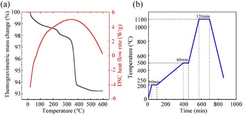
A simultaneous thermal analyser (TA SDT Q600, Scientific Compass, China) was employed to conduct thermogravimetric analysis (TGA) on the Ti/β-TCP composite porous green scaffolds, with a heating rate of 10°C/min, a test temperature range of 30–600°C and argon as the test environment. The TGA results are shown in (a). According to the TGA, the debinding and sintering curves are drawn as shown in (b). The temperature was increased from room temperature to 200°C at a rate of 5°C/min and then kept for 60 min. The temperature was increased to 500°C at a rate of 1°C/min and then kept for another 60 min. Then, at the sintering stage, the heating rate was set to 5°C/min and kept for 120 min after reaching the sintering temperature of 1100°C. The sintering temperature of the composite scaffold was determined according to the melting point of titanium and the phase transition temperature of β-TCP. The holding time and heating rate are the results of process optimisation. Then, the samples were cooled in the furnace.
Figure 1. (a) Differential scanning calorimeter characterisation of the dried precursor. (b) The sintering schedules investigated, holding at 1100°C for 2 h.
2.4. Characterisation of the scaffold
A field emission scanning electron microscope (SU8010, Hitachi, Japan) was used to observe the morphology of the powders and the sintered scaffolds. An X-ray diffractometer (XRD, Bruker D8 ADVANCE, China) was employed to conduct phase analysis on the original powders and sintered scaffolds, with a scanning speed of 2°/min.
The filament diameter of the printed green scaffolds was measured using an optical image measuring instrument (VML300, 3D FAMILY, China).
The porosity of the scaffolds was tested by Archimedes’ principle (Yi et al. Citation2020). The shrinkage rate of the specimens was obtained by measuring the linear shrinkage in the three directions of length, width and height before and after sintering (Song, Kenel, and Dunand Citation2020).
A mechanical testing machine was used to test the compressive strength of different groups of composite porous scaffolds. Four cylindrical samples (shape of the sample was cut by wire cutting) with the dimensions of Φ5*h9 mm3 were utilised in each group. The axial load was applied at a rate of 0.5 mm/min until the sample failed. Stress was defined as applied force divided by the projected area of sample's perimeter, and strain was defined as displacement divided by the height of sample. And, compressive stress and elastic modulus were calculated according to stress–strain curve.
2.5. In vitro biocompatibility test
The porous scaffolds in the B95Ti group (DIW-B98Ti) with 40% powder solid loading were prepared by DIW printing as the experimental group. DIW-printed pure titanium porous scaffolds with a solid loading of 40% (DIW-Ti) and SLM-printed porous titanium scaffolds (SLM-Ti) were used as control groups for the in vitro cell experiments. Disk samples with the dimensions of Φ10*h3 mm3 (shape of the sample was cut by wire cutting) were irradiated with Go60 for 24 h prior to use.
The mouse osteoblasts were evenly implanted on the scaffolds of each group at an inoculum density of 2 × 10⁴/cm2, and the prepared cell culture fluid (600 μL) was added. Then, the samples were placed in an incubator with 5% CO2 for culturing at 37°C, and the culture fluid was changed every 24 h.
The viability and distribution of the cells on the scaffold were observed by live/dead staining. The scaffold was removed on the first, third and seventh days of culture and washed with PBS three times to remove the residual esterase activity from the serum and other components of the culture solution. Then, a Calcein-AM/PI solution (100 μL) was added to the scaffold, followed by incubation at 37°C for 15 min. Fluorescence images were obtained using confocal laser scanning microscopy (A1, Nikon, Japan).
3. Results
3.1. Preparation of the ink and rheological properties
The morphology of the titanium powders is shown in (a,b). The titanium powders are spherical and have a smooth surface. The XRD test results are shown in (a). Compared to the standard JCPDS 89–2792 card, all diffraction peaks are consistent, indicating that there are no diffraction peaks of other oxides or carbides in the titanium powder.
Figure 2. SEM images of raw powders. (a) and (b) Ti, (c) and (d) β-TCP (S), (e) and (f) β-TCP (B).
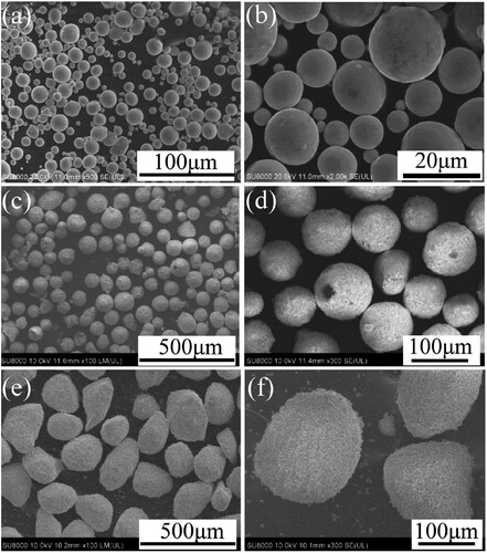
Figure 3. X-ray diffraction patterns of raw materials. (a) Ti powders, (b) β-TCP(S) powders and β-TCP(B) powders.
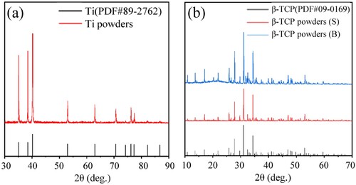
As indicated in (c–f), in the ceramic powder, some fine powder has even smaller particle sizes. β-TCP with a small particle size ((c,d)) has good sphericity and that with a big particle size ((e,f)) is ellipsoidal with a slightly poorer sphericity and a rough surface. The XRD analysis results are shown in (b). Comparison with the standard JCPDS 09-0169 card shows that the three main diffraction peaks of the β-TCP powder of two particle sizes are consistent with those of the standard card, indicating that they are all β phases and that there is no α-phase diffraction peak.
The impact of the β-TCP powder particle size, β-TCP/Ti powder ratio and solid loading on the ink viscosity is shown in . The change trends of the viscosity of the ink in each group with the shear rate are essentially the same. The initial viscosity is higher when the shear rate is low, and the viscosity decreases rapidly and tends to become stable with increasing shear rate. For the ink prepared with the big particle size β-TCP in each group, the viscosity increases significantly with the increase in the volume ratio of the β-TCP powder and is greater than that of the small particle size β-TCP composite ink at each β-TCP ratio. This is mainly a result of big β-TCP ceramic powders having big particle sizes and not being regular spheres, which increases the flow resistance in the ink and makes it difficult to damage the ink structure, resulting in a higher zero shear viscosity. For the ink prepared with the small particle size β-TCP, the viscosity does not evidently increase with the increase in the β-TCP powder ratio. β-TCP with a small particle size and good sphericity has little impact on the viscosity, as demonstrated by the similar viscosities.
Figure 4. Rheological properties of the ink as a function of powder solid loading and powder size. Viscosity profile as a function of shear rate of Ti, S95Ti, S90Ti, S85Ti and S80Ti inks with different powder solid loadings: (a) 20%, (c) 30% and (e) 40%. Viscosity profile as a function of shear rate of Ti, B95Ti, B90Ti, B85Ti and B80Ti inks with different powder solid loadings (b) 20%, (d) 30% and (f) 40%.
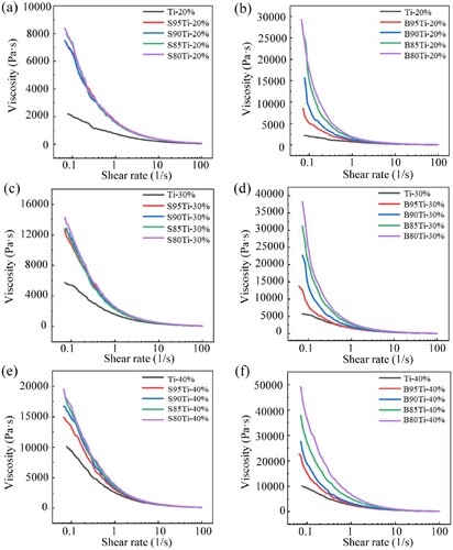
With the increase in the solid loading, the viscosity of the composite ink increases sharply. At a high shear rate, the viscosity is low and stable, which is beneficial for ink extrusion. The viscosities of the inks with different solid loadings prepared with the small particle size β-TCP powder differ significantly, mainly due to the increase in the solid loading.
3.2. DIW of the Ti/β-TCP composite scaffolds
The percentage of clogging of nozzles with different diameters is shown in (a). The nozzles with the diameters of 0.3 and 0.4 mm are both clogged, while those with diameters of 0.5, 0.6 and 0.7 mm can print as usual. The diameter of the filament is positively correlated with the nozzle diameter. A nozzle with a small diameter can provide a higher printing resolution. However, with high extrusion resistance, filament breakage easily occurs during the extrusion process, affecting the printing effect, and the filament diameter extruded from the nozzle has a direct impact on the size of the interlayer pores of the 3D porous structure. Considering the self-weight of the material and the large sintering shrinkage in the Z direction, a nozzle with a diameter of 0.6 mm is used to obtain interlayer pores greater than 400 μm that are beneficial for bone ingrowth.
Figure 5. Optimisation of the key parameters relevant to the printing of a single layer. (a) Percentage of clogging of the printed single layer with different nozzle diameters; (b) Printing pattern of the single layer; (c) Photographs of the printed single layer with different initial heights.
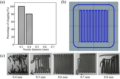
The printing pattern of a single layer is shown in (b). (c) shows the results of the first layer printing with different initial heights. All the initial heights fail to print the design pattern except for the initial height of 0.6 mm. When the initial height is smaller than the diameter of the nozzle, the extrusion of the ink is hindered, resulting in insufficient discharge. During the movement of the nozzle, the rear edge of the nozzle scratches the extruded material, leading to broken filaments. When the initial height is greater than the diameter of the nozzle, the ink cannot fully contact the platform so that the ink extruded at the initial stage of printing is easily dragged by the nozzle. As a result, it is impossible for the printing filament to bond to the platform to print the design pattern. Therefore, an initial height of 0.6 mm is selected for printing.
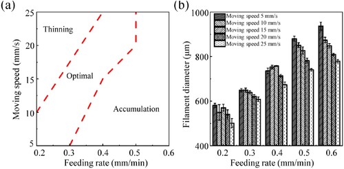
(a) shows a diagram of the relationship between the plunger feeding rate and the nozzle moving speed and the printability of the filaments. A large plunger feed speed combined with a small nozzle moving speed leads to too much extruded ink per unit time, with a very large filament diameter and very low porosity. A small plunger feed speed combined with a large nozzle moving speed results in inadequate extruded ink per unit time and a very thin filament and even broken filament. The plunger feed speed and the nozzle moving speed have a synergistic effect and are mutually influential. The printing process parameters are determined based on the statistical results for the filament diameter ((b)): the plunger feed speed is chosen as 0.3 mm/min, and the nozzle moving speed is set to 20 mm/s. The filament diameter under these process parameters is 621.32 ± 7.67 μm, and can easily approach the predesigned size of 600 μm through sintering shrinkage.
Figure 6. Effect of process parameters on the printed filaments. (a) Diagram of the relationship between the plunger feeding rate and nozzle moving speed and the printability of filaments. (b) Effect of the feeding rate and moving speed on the filament diameter.
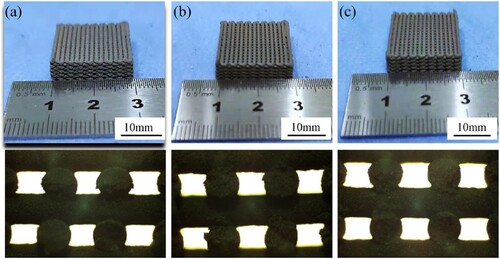
The interlayer bonding status of the scaffolds set with different layer heights for printing is shown in . When the layer height is 0.56 mm, too much material contact occurs between the layers, leading to extrusion deformation, an increase in the filament diameter and a decrease in the overall porosity. When the layer height is 0.58 mm, the interlayer contact is sufficient to maintain a good form. When the layer height is 0.6 mm, there is a small contact area between layers and untight bonding, affecting the strength of the scaffold. Therefore, a layer height of 0.58 mm is appropriate.
Figure 7. Effect of the layer height on the scaffold processing. (a) Layer height is 0.56 mm, (b) Layer height is 0.58 mm, (c) Layer height is 0.60 mm.
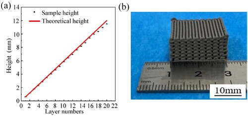
The optimised printing parameter combination is as follows: initial height of 0.6 mm, plunger feed speed of 0.3 mm/min, nozzle moving speed of 20 mm/s, and layer height of 0.58 mm. With these parameters, the 3D Ti/β-TCP composite porous scaffold is printed. The dimensions of the printed green scaffold in the Z direction are compared with those of the theoretical model, as shown in (a). With the increase in the number of printed scaffold layers, the actual height of the green scaffold gradually deviates from the theoretical height of the model within a small range but is close to the theoretical height. Thus, the porous scaffold prepared by the optimised printing parameters can effectively maintain its form and achieve high printing fidelity ((b)).
Figure 8. (a) Shape retention of the printed structure as a function of layer number. (b) Photograph of the printed porous Ti/β-TCP composite scaffold.
3.3. Characterisation of the Ti/β-TCP composite scaffold
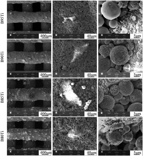
The microstructures of the sintered scaffolds in the pure titanium group and in the small particle size β-TCP group are shown in . The filament depositions are relatively smooth, free of deformation and twisting. The titanium particles are bonded to each other by a significant formation of sinter necks and indicates a porous morphology in pure titanium scaffold. The S95Ti group contains little β-TCP, and β-TCP on the surfaces of the scaffolds in the S90Ti, S85Ti and S80Ti groups shows a sharp rise and even distribution. The morphology of the titanium powders around the β-TCP powders changed from smooth to rough and uneven, particularly in the S80Ti group. A more pronounced sintering neck and a micropore structure between titanium powders that are not in contact with the β-TCP powders are observed. The microstructures of the sintered scaffolds in the big particle size β-TCP group are shown in . Due to the big particle size and poor sphericity of β-TCP, the ink is not quite stable during the process of extrusion, resulting in uneven and nonsmooth deposition of the filaments and a slight deformation. The morphology of the titanium powders around big β-TCP powders is also changed, and the surface where the titanium powders are close to the β-TCP powders becomes uneven. For the same content, bigger β-TCP powders with a smaller specific surface area can affect a smaller range of titanium powders, which is beneficial for the bonding of more titanium powders during sintering and the formation of sintering necks to enhance the fusion between titanium powders.
Figure 9. SEM images of sintered scaffolds of Ti, S95Ti, S90Ti, S85Ti, and S80Ti.
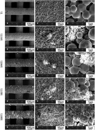
Figure 10. SEM images of sintered scaffolds of B95Ti, B90Ti, B85Ti, and B80Ti.
The test results for the shrinkage are shown in (a). The linear shrinkage of the sintered scaffolds was below 10%. The shrinkage of the composite porous scaffold prepared with big-particle-size β-TCP is much greater than that of the composite scaffold prepared with small-particle-size β-TCP. With the increase in the volume ratio of β-TCP, the shrinkage of the composite porous scaffolds prepared using β-TCP with the two particle sizes decreases, indicating that in the sintering process, the composite scaffold affects the contact and fusion between the titanium powders and reduces the shrinkage of the scaffold with the increase in the β-TCP content.
Figure 11. Mechanical properties as a function of composition. (a) Shrinkage, (b) porosity, (c) compressive strength and (d) elastic modulus of sintered Ti scaffolds and Ti/β-TCP scaffolds with different Ti/β-TCP powder ratios (5/95, 10/90, 15/85 and 20/80 vol%) and particle sizes (S and B).
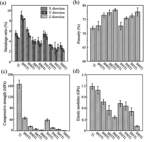
As shown in (b), the porosity of the composite porous scaffold prepared with big-particle-size β-TCP is slightly larger than that of the composite porous scaffold prepared with small-particle-size β-TCP. This difference is mainly due to the macroscopic size shrinkage of the scaffold. For the composite porous scaffolds with the same β-TCP particle size, those with a higher β-TCP volume ratio have a larger open porosity. The figure indicates that with the increase in the β-TCP volume ratio, β-TCP affects the bonding of the titanium powder and the formation of the sintering neck, produces more micropores with a larger size, and influences the overall increase in open porosity.
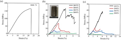
(c,d) show the compressive strengths and elastic modulus of the Ti scaffolds and composite porous scaffolds prepared by β-TCP of two particle sizes and shows the stress–strain curve of each group. The results indicate that regardless of the β-TCP particle size, the mechanical strength of the scaffold decreases with the increase in the volume ratio of the β-TCP powder. When the β-TCP powder volume ratio is the same, the composite porous scaffolds in the group of β-TCP with a big particle size have a higher open porosity and compressive strength than those in the group of β-TCP with a small particle size, with the compressive strength and elastic modulus of the B95Ti group reaching the maximum value, i.e. greater than 45 MPa and 1 GPa. Thus, β-TCP with a small particle size shows better performance than β-TCP with a big particle size in weakening the mechanical properties of the composite scaffold. The mechanical strength of pure titanium scaffolds is higher than the composite scaffolds due to the sufficiently contact between the single-material titanium powders.
Figure 12. Stress-strain curves of sintered Ti scaffolds and Ti/β-TCP scaffolds with different Ti/β-TCP powder ratios (5/95, 10/90, 15/85 and 20/80 vol%) and particle sizes (S and B).
3.4. Cell culture experiment
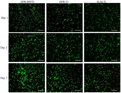
The results of live/dead staining for the cells are shown in . Over time, the number of living cells in each group increased, although the number of dead cells was limited. At each time point, the number of living cells in the DIW-B95Ti group was greater than that in the DIW-Ti and SLM-Ti groups. This finding suggests that each group of porous scaffolds has good cytocompatibility, and cells can adhere and proliferate on the scaffolds of each group. In particular, the DIW-B95Ti group with β-TCP on the surface had a greater ability than the other two groups to promote cell adhesion and proliferation. The porous scaffold prepared by DIW has micropores on the surface after sintering. The larger surface area and rough surface morphology of these micropores cause cell attachment and thus enhance cell proliferation.
Figure 13. Fluorescence images of MC-3T3 cells cultured in DIW-B95Ti, DIW-Ti, and SLM-Ti scaffolds for 1, 3 and 7 d.
4. Discussion
To prepare a metal-bioceramic composite bone repair scaffold, titanium and β-TCP were selected as the main materials in this study. Compared to Ti6Al4 V used in other literature (Yi et al. Citation2020; Li et al. Citation2021) investigations, titanium has excellent mechanical properties and can provide good mechanical support for large bone defects without the risk of releasing harmful ions. β-Ti alloys have been used as potential materials for biomedical applications due to their higher strength and lower modulus (Sing Citation2022). β-Ti alloys consist of various nontoxic elements, such as tantalum, niobium, molybdenum, tin, and zirconium. In the process of co-sintering with TCP, more complex reactions will occur on the interface that are difficult to control. Zn has been regarded as a novel potential implant biomaterial due to its desirable biodegradability and good biocompatibility, but its low strength and ductility limit its application in bone repair (Gao et al. Citation2019; Zhou et al. Citation2022). Mg alloy is a light alloy with low density and high specific strength. It should be noted that Mg degrades too rapidly in the human body environment and does not match the rate of new bone formation (Zhou et al. Citation2022; Shuai et al. Citation2018; Liu et al. Citation2022). For bioceramic materials in composite scaffolds, the use of both α-TCP and HA has been studied. α-TCP dissolves very quickly, and its sintering temperature is high. It expands during the phase transition, leading to a decrease in its mechanical properties. β-TCP has better biodegradability and osteogenic properties than HA. After degradation, secondary pores are produced to enhance bone ingrowth. Most importantly, β-TCP has good biological activity and stable chemical properties at high temperatures (Cho et al. Citation2007).
DIW 3D printing technology is an additive manufacturing method based on material extrusion. The rheological properties of the composite ink play a key role in the smooth extrusion of the ink and its ability to bear its own weight and maintain its shape without collapsing. Each group of composite inks prepared with β-TCP powders, titanium powders and aqueous F127 binder solution is a non-Newtonian fluid suitable for DIW printing. At a low shear rate, the structure of an ink with a large viscosity is damage resistant and the ink has a high flow resistance. At a high shear rate, its viscosity is greatly reduced, its structure can be easily damaged, and its flow resistance is low, reflecting the shear thinning of the ink.
In essence, the plunger feed speed controls the speed of the material flowing out of the nozzle, and the nozzle moving speed controls the speed of material deposition (Li et al. Citation2006). The coordination between the two involves flow matching. When the layer height and the nozzle diameter are essentially the same, the speed of material extrusion through the nozzle ideally is equal to the speed of material deposition. The goal of process optimisation is to achieve a material extrusion speed equivalent to the material deposition speed by adjusting the plunger feed speed and nozzle moving speed. Then, the filament can complete the deposition process in a more natural state. If the two speeds do not match, the filaments are pulled or pile up, affecting the modelling effect. The pore size and porosity of green scaffolds are also related to the plunger feed speed and nozzle moving speed, and good control of the spacing printed line and dimensions can be realised by optimising the printing process parameters.
In the process of debinding and sintering, at the stage from room temperature to 200 °C, binder pyrolysis has not yet begun; thus, a slightly faster heating rate (5 °C/min) can be set to reduce the process time. At 200–500 °C, the binder begins to decompose. Since the composite ink binder in this study is water-based F127 with a simple and nontoxic composition, it is unnecessary to set multiple temperature stages in the debinding stage. However, to prevent too much volatilised gas generated by the pyrolysis of the binder from quickly damaging the scaffold structure, the heating rate at this stage should be reduced to 1°C/min. After entering the sintering stage above 500 °C, the heating rate can be increased so that the titanium powders can be sintered as quickly as possible to improve the strength of the scaffold. However, because an excessively high heating rate causes uneven heating of the scaffold, the heating rate in the sintering stage was set to 5°C/min. After reaching the sintering temperature, it was kept for 2 h to continue to strengthen the bonding between the titanium powders and improve the strength of the scaffold. Then, the sample can cool with the furnace to reduce the internal thermal stress of the scaffold.
Through high-temperature sintering, green scaffolds obtain a higher strength that is necessary for the preparation of metal/ceramic composite scaffolds. Unlike the traditional additive manufacturing methods (e.g. SLM and EBM) that can only manufacture single materials (Attar et al. Citation2018; Trevisan et al. Citation2018; Zhang, Fang, and Zhou Citation2017), DIW printing provides a novel manufacturing method for the preparation of multimaterial composite scaffolds.
β-TCP powders are distributed in the titanium powders, which can affect the bonding of the titanium powders during sintering. and reveal that during the sintering process, the titanium powder surface in contact with the β-TCP powder becomes rough. This finding indicates that chemical reaction and interdiffusion may occur between the two materials, affecting the bonding between the titanium powders. Oxygen and phosphorus in β-TCP with a small particle size easily diffuse to react with titanium to generate brittle phases, weakening the mechanical strength of the scaffold. The spatial distribution and contact area of the β-TCP powders with different particle sizes become different after mixing with the titanium powder, which also affects the sintering behaviour and microstructure of the composite scaffold and thus affects the mechanical properties of the scaffold. The β-TCP powder with a small particle size dispersed in the scaffold has a large specific surface area and a larger contact area with the titanium powder, reducing the formation of titanium powder sintering necks. The β-TCP powder with a small particle size has a greater influence on the mechanical properties of the scaffold.
The compressive strength and elastic modulus of human cancellous bone are 10–50 MPa and 0.01–3 GPa (Ruan et al. Citation2016), respectively. In this study, in the B95Ti group, the composite porous scaffold was prepared using β-TCP powder with a big particle size and titanium powder using DIW 3D printing technology, and the compressive strength and elastic modulus reached 45.81 ± 3.89 MPa and 1.09 ± 0.10 GPa when the porosity is 72.54%, which close to the human cancellous bone. The scaffold dose not lead to stress shielding.
The cytocompatibility of the scaffold in the DIW-B95Ti group was better than that of the other groups. On the one hand, β-TCP on the surface of the scaffold is a bioactive material that is beneficial for cell adhesion and proliferation. The biological performance of the scaffold is improved by adding β-TCP. On the other hand, the contact and fusion between the titanium powders in the sintering process produces a microporous structure that can provide good adhesion sites for cells. Therefore, the DIW-Ti group shows better biological performance than the SLM-Ti group. With a dense surface, the titanium scaffold prepared by SLM technology has no microporous structure. The scaffold in the DIW-B95Ti group had a strength close to that of human cancellous bone and better biological properties than pure titanium. The DIW-B95Ti group scaffold with both good mechanical and biological properties exhibited controllable macroscopic pores and sintered hierarchical microscopic pore structures, that met the requirements for a bone implant, it has a certain potential for application.
SLM has been successfully employed for the fabrication of metal scaffolds and metal-based composites (Trevisan et al. Citation2018; Zhang, Fang, and Zhou Citation2017; Gao et al. Citation2019; Rahmani et al. Citation2022; Tan et al. Citation2017; Sing et al. Citation2016; Maszybrocka et al. Citation2017; Attar et al. Citation2018). This technique uses a laser beam as the energy source and a small beam spot diameter and fine powder, therefore exhibiting relatively high dimensional accuracy and resolution (Zhou et al. Citation2022). Compared to DIW, the main advantage of the SLM technique is its flexibility, which allows for the fabrication of complex geometries. In addition, complete powder melting results in high-density parts, and the strength of the SLM-printed scaffold is higher than that of the DIW – printed scaffold. Due to its high density, the bone scaffold prepared by SLM with a dense surface has no micropores, which is not conducive to cell adhesion and the formation of new bone. DIW technology possesses remarkable advantages for the fabrication of a porous bone scaffold. Because the micropores can be produced by the contact and fusion of particles during the sintering process, the sintered micropores can improve the osseointegration between implant and the hosting bone tissues.
DIW has some limitations that should be mentioned. First, a technology with a low resolution offers less flexibility in terms of the structure that can be designed and produced than the SLM techniques (Zhang et al. Citation2021). Second, there is a lower limit of the nozzle size that can be used, and therefore, the limitation in filament size that can be achieved. Finally, the deviation between the actual height and theoretical height in the z-direction increases with increasing layer number.
In future work, we will further optimise the ink preparation and manufacturing parameters to achieve geometries with high porosities and high mechanical properties. Further in vitro and in vivo studies are needed to evaluate the potential of Ti/β-TCP composite porous scaffolds fabricated by DIW.
5. Conclusion
A Ti/β-TCP composite porous bone scaffold with both good mechanical and biological properties was prepared by DIW 3D printing technology. It exhibited controllable macroscopic pores and sintered hierarchical microscopic pore structures, with the mechanical strength reaching close to that of human cancellous bone. In addition, the scaffold showed better biocompatibility than pure titanium scaffolds, providing broad prospects for the application of metal/ceramic composite porous scaffolds in bone repair and reconstruction.
DIW 3D printing can use titanium powders and β-TCP powder as the raw materials. By mixing the powders with the green and safe water-based binder F127, ink with a high solid content can be prepared. At room temperature, a Ti/β-TCP composite porous bone green scaffold with controllable macroscopic pores and sintered hierarchical microscopic pore structures is fabricated by extruding ink.
Through vacuum sintering at high temperature, the scaffold had a shrinkage of less than 10%. The features of small shrinkage and deformation and ease of control are beneficial for maintaining the morphology of the porous structures.
The compressive strength and elastic modulus of the porous scaffolds in the B95Ti group were 45.81 ± 3.89 MPa and 1.09 ± 0.10 GPa, when the porosity is 72.54%, even reaching close to the strength of cancellous bone.
The β-TCP and sintered micropores on the surface of the scaffold that can promote the binding of osteoblasts to the surface of the scaffold to improve the biological properties of the scaffold. The cytocompatibility of the scaffold in the DIW-B95Ti group was better than that in the pure titanium groups.
Disclosure statement
No potential conflict of interest was reported by the author(s).
Additional information
Funding
Notes on contributors
Guangbin Zhao
Guangbin Zhao received his Ph.D. in Mechanical Engineering from Xi'an Jiaotong University in 2021. He works as an Assistant Professor at State Key Laboratory for Manufacturing System Engineering in Xi'an Jiaotong University. He aims at fabrication of multifunctional scaffolds, and further use them towards tissue repair, antibacterial and tumour therapy.
Qingxian Zhang
Qingxian Zhang received his M.E in Mechanical Engineering from Xi'an Jiaotong University(2022). He works on 3D printing of composite bone implants.
Xiaoli Qu
Xiaoli Qu is a Ph.D. candidate at Xi'an Jiaotong University. Her research focuses on vascularised tissue construction and regulation of cellular behaviour under complex biological microenvironments.
Yanlong Wu
Yanlong Wu received his Ph.D. in Mechanical Engineering from Xi'an Jiaotong University(2022). He is a postdoctoral researcher at Foshan University and Ji Hua Laboratory, mainly engaged in 3D printing of composite bone implants.
Xu Chen
Xu Chen received his BS in mechanical engineering and automation from Dalian University of Technology. Now he is a Ph.D. candidate in Mechanical Engineering at Xi'an Jiaotong University (2022). He worked on the optimisation and design of orthopedic implants and 3D printing.
Yaning Wang
Yaning Wang is a Ph.D. candidate at Xi'an Jiaotong University. His research interests include 3D printing, microfabrication and motion control.
Hang Tian
Hang Tian is a master’s student at Xi'an University of Science and Technology, and his main research topic is 3D printing porous metal materials.
Yaxiong Liu
Yaxiong Liu, the corresponding author of this manuscript, works as a Professor at Ji Hua Laboratory. His research interests focus on developing new methods, technologies and explore new applications in the field of biomanufacturing and 3D printing.
Zhikang Li
Zhikang Li received his Ph.D. in Mechanical Engineering from Xi'an Jiaotong University in 2017. He currently serves as an Associate Professor at State Key Laboratory for Manufacturing System Engineering in Xi'an Jiaotong University. His research interests is 3D printing porous scaffolds and wearable sensors.
Bingheng Lu
Bingheng Lu works at Xi'an Jiaotong University. He is an academician of Chinese Academy of Engineering. He is one of the earliest scholars to research 3D printing in China.
References
- Attar, Hooyar, Matthias Bönisch, Mariana Calin, Lai-Chang Zhang, Sergio Scudino, and Jürgen Eckert. 2014. “Selective Laser Melting of in Situ Titanium–Titanium Boride Composites: Processing, Microstructure and Mechanical Properties.” Acta Materialia 76: 13–22. doi:10.1016/j.actamat.2014.05.022.
- Attar, Hooyar, Shima Ehtemam-Haghighi, Damon Kent, and Matthew S. Dargusch. 2018. “Recent Developments and Opportunities in Additive Manufacturing of Titanium-Based Matrix Composites: A Review.” International Journal of Machine Tools and Manufacture 133: 85–102. doi:10.1016/j.ijmachtools.2018.06.003.
- Bose, Susmita, Samuel Ford Robertson, and Amit Bandyopadhyay. 2018. “Surface Modification of Biomaterials and Biomedical Devices Using Additive Manufacturing.” Acta Biomaterialia 66: 6–22. doi:10.1016/j.actbio.2017.11.003.
- Chen, Yunhui, Damon Kent, Michael Bermingham, Ali Dehghan-Manshadi, and Matthew Dargusch. 2017. “Manufacturing of Biocompatible Porous Titanium Scaffolds Using a Novel Spherical Sugar Pellet Space Holder.” Materials Letters 195: 92–95. doi:10.1016/j.matlet.2017.02.092.
- Cho, In-Sun, Hyun-Seung Ryu, Jeong-Ryeol Kim, Dong-Wan Kim, and Kug Sun Hong. 2007. “Sintering Behavior and Microwave Dielectric Properties of Tricalcium Phosphate Polymorphs.” Japanese Journal of Applied Physics 46 (5A): 2999–3003. doi:10.1143/JJAP.46.2999.
- Diao, Yunhua, and Kemin Zhang. 2015. “Microstructure and Corrosion Resistance of TC2 Ti Alloy by Laser Cladding with Ti/TiC/TiB2 Powders.” Applied Surface Science 352: 163–168. doi:10.1016/j.apsusc.2015.04.030.
- Eraković, S., A. Janković, C. Ristoscu, L. Duta, N. Serban, A. Visan, I. N. Mihailescu, et al. 2014. “Antifungal Activity of Ag:Hydroxyapatite Thin Films Synthesized by Pulsed Laser Deposition on Ti and Ti Modified by TiO2 Nanotubes Substrates.” Applied Surface Science 293: 37–45. doi:10.1016/j.apsusc.2013.12.029.
- Feng, Chun, Wenjie Zhang, Cuijun Deng, Guanglong Li, Jiang Chang, Zhiyuan Zhang, Xinquan Jiang, and Chengtie Wu. 2017. “3D Printing of Lotus Root-Like Biomimetic Materials for Cell Delivery and Tissue Regeneration.” Advanced Science 4 (12): 1700401. doi:10.1002/advs.201700401.
- Gao, Chengde, Shuping Peng, Pei Feng, and Cijun Shuai. 2017. “Bone Biomaterials and Interactions with Stem Cells.” Bone Research 5 (1): 17059. doi:10.1038/boneres.2017.59.
- Gao, C. D., M. Yao, C. J. Shuai, S. P. Peng, and Y. W. Deng. 2019. “Nano-SiC Reinforced Zn Biocomposites Prepared via Laser Melting: Microstructure, Mechanical Properties and Biodegradability.” Journal of Materials Science & Technology 35 (11): 2608–2617. doi:10.1016/j.jmst.2019.06.010.
- Hu, Yingbin, Weilong Cong, Xinlin Wang, Yuanchen Li, Fuda Ning, and Hui Wang. 2018. “Laser Deposition-Additive Manufacturing of TiB-Ti Composites with Novel Three-Dimensional Quasi-Continuous Network Microstructure: Effects on Strengthening and Toughening.” Composites Part B: Engineering 133: 91–100. doi:10.1016/j.compositesb.2017.09.019.
- Hung, Kuo-Yung, Sung-Cheng Lo, Chung-Sheng Shih, Yung-Chin Yang, Hui-Ping Feng, and Yi-Chih Lin. 2013. “Titanium Surface Modified by Hydroxyapatite Coating for Dental Implants.” Surface and Coatings Technology 231: 337–345. doi:10.1016/j.surfcoat.2012.03.037.
- Jakus, Adam E., Shannon L. Taylor, Nicholas R. Geisendorfer, David C. Dunand, and Ramille N. Shah. 2015. “Metallic Architectures from 3D-Printed Powder-Based Liquid Inks.” Advanced Functional Materials 25 (45): 6985–6995. doi:10.1002/adfm.201503921.
- Kenel, Christoph, Nicola P. M Casati, and David C. Dunand. 2019. “3D ink-Extrusion Additive Manufacturing of CoCrFeNi High-Entropy Alloy Micro-Lattices.” Nature Communications 10 (1): 904. doi:10.1038/s41467-019-08763-4.
- Kleger, Nicole, Martina Cihova, Kunal Masania, André R. Studart, and Jörg F. Löffler. 2019. “3D Printing: 3d Printing of Salt as a Template for Magnesium with Structured Porosity.” Advanced Materials 31 (37): 1970260. doi:10.1002/adma.201970260.
- Laurencin, Cato, Yusuf Khan, and Saadiq F. El-Amin. 2006. “Bone Graft Substitutes.” Expert Review of Medical Devices 3 (1): 49–57. doi:10.1586/17434440.3.1.49.
- Lewis, Phillip L., and Ramille N. Shah. 2016. “3D Printing for Liver Tissue Engineering: Current Approaches and Future Challenges.” Current Transplantation Reports 3 (1): 100–108. doi:10.1007/s40472-016-0084-y.
- Li, Jia Ping, Joost R. de Wijn, Clemens A. Van Blitterswijk, and Klaas de Groot. 2006. “Porous Ti6Al4V Scaffold Directly Fabricating by Rapid Prototyping: Preparation and in Vitro Experiment.” Biomaterials 27 (8): 1223–1235. doi:10.1016/j.biomaterials.2005.08.033.
- Li, J., H. Yuan, A. Chandrakar, L. Moroni, and P. Habibovic. 2021. “3D Porous Ti6Al4V-Beta-Tricalcium Phosphate Scaffolds Directly Fabricated by Additive Manufacturing.” Acta Biomaterialia 126: 496–510. doi:10.1016/j.actbio.2021.03.021.
- Li, Tian, Dong Zhai, Bing Ma, Jianmin Xue, Pengyu Zhao, Jiang Chang, Michael Gelinsky, and Chengtie Wu. 2019. “3D Printing of Hot Dog-Like Biomaterials with Hierarchical Architecture and Distinct Bioactivity.” Advanced Science 6 (19): 1901146. doi:10.1002/advs.201901146.
- Liu, Chuyi, Chengrong Ling, Cheng Chen, Dongsheng Wang, Youwen Yang, Deqiao Xie, and Cijun Shuai. 2022. “Laser Additive Manufacturing of Magnesium Alloys and its Biomedical Applications.” Materials Science in Additive Manufacturing 1 (4): 24. doi:10.18063/msam.v1i4.24.
- Majumdar, Trina, Neil Eisenstein, Jess E. Frith, Sophie C. Cox, and Nick Birbilis. 2018. “Additive Manufacturing of Titanium Alloys for Orthopedic Applications: A Materials Science Viewpoint.” Advanced Engineering Materials 20 (9): 1800172. doi:10.1002/adem.201800172.
- Maszybrocka, J., A. Stwora, B. Gapinski, G. Skrabalak, and M. Karolus. 2017. “Morphology and Surface Topography of Ti6Al4V Lattice Structure Fabricated by Selective Laser Sintering.” Bulletin of the Polish Academy of Sciences Technical Sciences (1): 85–92. doi:10.1515/bpasts-2017-0011.
- Montazerian, Maziar, Fatemeh Hosseinzadeh, Carla Migneco, Marcus V. L. Fook, and Francesco Baino. 2022. “Bioceramic Coatings on Metallic Implants: An Overview.” Ceramics International 48 (7): 8987–9005. doi:10.1016/j.ceramint.2022.02.055.
- Montazerolghaem, M., A. Rasmusson, H. Melhus, H. Engqvist, and M. Karlsson Ott. 2016. “Simvastatin-doped pre-Mixed Calcium Phosphate Cement Inhibits Osteoclast Differentiation and Resorption.” Journal of Materials Science: Materials in Medicine 27 (5): 83. doi:10.1007/s10856-016-5692-7.
- Munir, K. S., Y. Li, and C. Wen. 2017. “1 - Metallic Scaffolds Manufactured by Selective Laser Melting for Biomedical Applications.” Metallic Foam Bone, 1–23. doi:10.1016/B978-0-08-101289-5.00001-9.
- Ober, T. J., D. Foresti, and J. A. Lewis. 2015. “Active Mixing of Complex Fluids at the Microscale.” Proceedings of the National Academy of Sciences 112 (40): 12293–12298. doi:10.1073/pnas.1509224112.
- Omran, A. M., Kee Do Woo, Duck Soo Kang, G. T. Abdel-Gaber, H. Fouad, Hany S. Abdo, and Khalil Abdelrazek Khalil. 2015. “Fabrication and Evaluation of Porous Ti–HA bio-Nanomaterial by Leaching Process.” Arabian Journal of Chemistry 8 (3): 372–379. doi:10.1016/j.arabjc.2014.11.052.
- Paredes, Claudia, Francisco J. Martínez-Vázquez, Antonia Pajares, and Pedro Miranda. 2019. “Novel Strategy for Toughening Robocast Bioceramic Scaffolds Using Polymeric Cores.” Ceramics International 45 (15): 19572–19576. doi:10.1016/j.ceramint.2019.06.175.
- Pei, X., L. Ma, B. Zhang, J. Sun, Y. Sun, Y. Fan, Z. Gou, C. Zhou, and X. Zhang. 2017. “Creating Hierarchical Porosity Hydroxyapatite Scaffolds with Osteoinduction by Three-Dimensional Printing and Microwave Sintering.” Biofabrication 9 (4): 0045008. doi:10.1088/1758-5090/aa90ed.
- Rahmani, R., N. Kamboj, M. Brojan, M. Antonov, and K. G. Prashanth. 2022. “Hybrid Metal-Ceramic Biomaterials Fabricated Through Powder bed Fusion and Powder Metallurgy for Improved Impact Resistance of Craniofacial Implants.” Materialia 24. doi:10.1016/j.mtla.2022.101465.
- Roy, Mangal, Vamsi Krishna Balla, Amit Bandyopadhyay, and Susmita Bose. 2011. “Compositionally Graded Hydroxyapatite/Tricalcium Phosphate Coating on Ti by Laser and Induction Plasma.” Acta Biomaterialia 7 (2): 866–873. doi:10.1016/j.actbio.2010.09.016.
- Ruan, Jianming, Hailin Yang, Xiaojun Weng, Jinglei Miao, and Kechao Zhou. 2016. “Preparation and Characterization of Biomedical Highly Porous Ti–Nb Alloy.” Journal of Materials Science: Materials in Medicine 27 (4): 76. doi:10.1007/s10856-016-5685-6.
- Shen, Jianhua, Xianyan Yang, Ronghuan Wu, Miaoda Shen, Fengling Lu, Feng Zhang, Zhao Chen, et al. 2020. “Direct ink Writing Core-Shell Wollastonite@Diopside Scaffolds with Tailorable Shell Micropores Favorable for Optimizing Physicochemical and Biodegradation Properties.” Journal of the European Ceramic Society 40 (2): 503–512. doi:10.1016/j.jeurceramsoc.2019.09.049.
- Shin, J. H., J. H. Kim, J. T. Koh, H. P. Lim, G. J. Oh, S. W. Lee, K. M. Lee, K. D. Yun, and S. W. Park. 2015. “Preparation and Characterisation of Hydroxyapatite Coatings on Nanotubular TiO/SUB Surface Obtained by Sol–Gel Process.” Journal of Nanoscience and Nanotechnology 15 (8): 6164–6167. doi:10.1166/jnn.2015.10456.
- Shuai, C. J., C. X. He, L. Xu, Q. Li, T. Chen, Y. W. Yang, and S. P. Peng. 2018. “Wrapping Effect of Secondary Phases on the Grains: Increased Corrosion Resistance of Mg-Al Alloys.” Virtual and Physical Prototyping 13 (4): 292–300. doi:10.1080/17452759.2018.1479969.
- Sing, S. L. 2022. “Perspectives on Additive Manufacturing Enabled Beta- Titanium Alloys for Biomedical Applications.” International Journal of Bioprinting 8 (1): 478–478. doi:10.18063/ijb.v8i1.478.
- Sing, S. L., W. Y. Yeong, F. E. Wiria, and B. Y. Tay. 2016. “Characterization of Titanium Lattice Structures Fabricated by Selective Laser Melting Using an Adapted Compressive Test Method.” Experimental Mechanics 56 (5): 735–748. doi:10.1007/s11340-015-0117-y.
- Song, Binna, Christoph Kenel, and David C. Dunand. 2020. “3D ink-Extrusion Printing and Sintering of Ti, Ti-TiB and Ti-TiC Microlattices.” Additive Manufacturing 35: 101412. doi:10.1016/j.addma.2020.101412.
- Surmenev, Roman A., Maria A. Surmeneva, and Anna A. Ivanova. 2014. “Significance of Calcium Phosphate Coatings for the Enhancement of new Bone Osteogenesis – A Review.” Acta Biomaterialia 10 (2): 557–579. doi:10.1016/j.actbio.2013.10.036.
- Tan, X. P., Y. J. Tan, C. S. L. Chow, S. B. Tor, and W. Y. Yeong. 2017. “Metallic Powder-bed Based 3D Printing of Cellular Scaffolds for Orthopaedic Implants: A State-of-the-art Review on Manufacturing, Topological Design, Mechanical Properties and Biocompatibility.” Materials Science and Engineering: C, doi:10.1016/j.msec.2017.02.094.
- Taniguchi, Naoya, Shunsuke Fujibayashi, Mitsuru Takemoto, Kiyoyuki Sasaki, Bungo Otsuki, Takashi Nakamura, Tomiharu Matsushita, Tadashi Kokubo, and Shuichi Matsuda. 2016. “Effect of Pore Size on Bone Ingrowth Into Porous Titanium Implants Fabricated by Additive Manufacturing: An in Vivo Experiment.” Materials Science and Engineering: C 59: 690–701. doi:10.1016/j.msec.2015.10.069.
- Thian, E. S., N. H. Loh, K. A. Khor, and S. B. Tor. 2002a. “In Vitro Behavior of Sintered Powder Injection Molded Ti-6Al-4V/HA.” Journal of Biomedical Materials Research 63 (2): 79–87. doi:10.1002/jbm.10082.
- Thian, E. S., N. H. Loh, K. A. Khor, and S. B. Tor. 2002b. “Microstructures and Mechanical Properties of Powder Injection Molded Ti-6Al-4V/HA Powder.” Biomaterials 23 (14): 2927–2938. doi:10.1016/S0142-9612(01)00422-7.
- Trevisan, F., F. Calignano, A. Aversa, G. Marchese, M. Lombardi, S. Biamino, D. Ugues, and D. Manfredi. 2018. “Additive Manufacturing of Titanium Alloys in the Biomedical Field: Processes, Properties and Applications.” Journal of Applied Biomaterials & Functional Materials 16 (2): 57–67. doi:10.5301/jabfm.5000371.
- Wang, Wenhao, and Kelvin W. K. Yeung. 2017. “Bone Grafts and Biomaterials Substitutes for Bone Defect Repair: A Review.” Bioactive Materials 2 (4): 224–247. doi:10.1016/j.bioactmat.2017.05.007.
- Xia, Lunguo, Youtao Xie, Bing Fang, Xiuhui Wang, and Kaili Lin. 2018. “In Situ Modulation of Crystallinity and Nano-Structures to Enhance the Stability and Osseointegration of Hydroxyapatite Coatings on Ti-6Al-4V Implants.” Chemical Engineering Journal 347: 711–720. doi:10.1016/j.cej.2018.04.045.
- Yang, Youwen, Chongxian He, E. Dianyu, Wenjing Yang, Fangwei Qi, Deqiao Xie, Lida Shen, Shuping Peng, and Cijun Shuai. 2020. “Mg Bone Implant: Features, Developments and Perspectives.” Materials & Design 185: 108259. doi:10.1016/j.matdes.2019.108259.
- Yi, Tao, Changchun Zhou, Liang Ma, Lina Wu, Xiujuan Xu, Linxia Gu, Yujiang Fan, Guang Xian, Hongyuan Fan, and Xingdong Zhang. 2020. “Direct 3-D Printing of Ti-6Al-4V/HA Composite Porous Scaffolds for Customized Mechanical Properties and Biological Functions.” Journal of Tissue Engineering and Regenerative Medicine 14 (3): 486–496. doi:10.1002/term.3013.
- Yuk, Hyunwoo, and Xuanhe Zhao. 2018. “A New 3D Printing Strategy by Harnessing Deformation, Instability, and Fracture of Viscoelastic Inks.” Advanced Materials 30 (6): 1704028. doi:10.1002/adma.201704028.
- Zhang, Y. T., S. Attarilar, L. Q. Wang, W. J. Lu, J. L. Yang, and Y. F. Fu. 2021. “A Review on Design and Mechanical Properties of Additively Manufactured NiTi Implants for Orthopedic Applications.” International Journal of Bioprinting 7 (2): 15–42. doi:10.18063/ijb.v7i2.340.
- Zhang, Faming, Jiang Chang, Jianxi Lu, Kaili Lin, and Congqin Ning. 2007. “Bioinspired Structure of Bioceramics for Bone Regeneration in Load-Bearing Sites.” Acta Biomaterialia 3 (6): 896–904. doi:10.1016/j.actbio.2007.05.008.
- Zhang, Lai-Chang, and Liang-Yu Chen. 2019. “A Review on Biomedical Titanium Alloys: Recent Progress and Prospect.” Advanced Engineering Materials 21 (4): 1801215. doi:10.1002/adem.201801215.
- Zhang, X. Y., G. Fang, and J. Zhou. 2017. “Additively Manufactured Scaffolds for Bone Tissue Engineering and the Prediction of Their Mechanical Behavior: A Review.” Materials 10 (1): 50. doi:10.3390/ma10010050.
- Zhao, Shanyu, Gilberto Siqueira, Sarka Drdova, David Norris, Christopher Ubert, Anne Bonnin, Sandra Galmarini, et al. 2020. “Additive Manufacturing of Silica Aerogels.” Nature 584 (7821): 387–392. doi:10.1038/s41586-020-2594-0.
- Zhou, Y., J. W. Wang, Y. W. Yang, M. L. Yang, H. Z. Zheng, D. Q. Xie, D. S. Wang, and L. D. Shen. 2022. “Laser Additive Manufacturing of Zinc Targeting for Biomedical Application.” International Journal of Bioprinting 8 (1): 501–522. doi:10.18063/ijb.v8i1.501.