
 ?Mathematical formulae have been encoded as MathML and are displayed in this HTML version using MathJax in order to improve their display. Uncheck the box to turn MathJax off. This feature requires Javascript. Click on a formula to zoom.
ABSTRACT
In this paper, 20Mn2SiCrMo bainitic crossing noses were repaired by depositing 420SS, Stellite 6, 17-4PH and 18Ni300 alloys on the rail surfaces to form functionally graded materials (FGM) using laser directed energy deposition (L-DED) technology. As a result, only 18Ni300 deposit achieves an excellent strength-toughness combination, which possesses a yield strength of ∼1120 MPa together with an impact energy of ∼85.05 J, better than those of substrates (∼1071 MPa, ∼71.34 J). Besides, the wear and rolling contact fatigue (RCF) resistance of 20Mn2SiCrMo/18Ni300 FGM is enhanced to 2.7 and 23.6 times as much as those of substrates. Massive ultrafine nanoprecipitates and a small amount of austenite make 18Ni300 deposit strong enough as well as a certain work-hardenability, ensuring good wear resistance therein; the significant RCF resistance originates from the improved shakedown limit. Therefore, all findings reveal that 18Ni300 is the most promising depositing material for repairing bainitic crossing noses by L-DED.
1. Introduction
The crossing nose, as an essential part of the railway crossing, is subjected to substantial wear and impact loads when the train changes tracks, which usually causes severe damages such as wear, plastic deformation, shelling, lipping and spalling (Lai et al. Citation2017; W. J. Wang et al. Citation2016a). Recently, carbide-free bainitic steels possessing the tensile strength of 1400 MPa have been successfully applied to the crossing noses in China (Kumar et al. Citation2019), which can increase the carrying capacity of railroads to 200 million tons. However, the crossing noses still require more frequent grinding and replacement than standard rails, which increases the operating cost of the railway network and limits its development of high-speed and heavy-duty. Therefore, compared to direct replacement, timely repair of damaged crossing noses by appropriate on-site repair methods can significantly reduce material waste and operating cost, which is an economic and sustainable development strategy.
Laser directed energy deposition (L-DED), an important additive manufacturing technology (S. Wang et al. Citation2022; Z. Yang et al. Citation2021), can regenerate damaged parts by restoring the geometry and optimising the microstructure. L-DED shows great potential in the repair the worn parts by preparing functionally graded materials (FGM) (Kanishka and Acherjee Citation2023; L. Zhu et al. Citation2020). On the one hand, L-DED has high deposition efficiency and flexibility (X. Yang et al. Citation2022a; L. Zhu et al. Citation2022), and on the other hand, the low heat input can cause small heat affected zone (HAZ) and fine-structured deposits (Z. D. Wang et al. Citation2021).
Recently, L-DED has been widely utilised in the repair and strengthening of standard rails (Franklin et al. Citation2005; H.-M. Guo et al. Citation2015). For example, the European research project ‘INFRASTAR’ pioneered the study about depositing wear-resistant materials on standard R260 grade rails by L-DED, and the results of a trial application in Sweden showed that the rolling contact fatigue (RCF) resistance of the two-material rails is superior to the untreated rails (Hiensch et al. Citation2003). K. Wang et al. (Citation2016c) fabricated Fe-based alloys on the surface of the Chinese U71Mn rails by L-DED, which improved the microhardness and wear resistance therein. Lai et al. (Citation2019) repaired the hypereutectoid rails by L-DED technique with heating treatment, and the results of roller-on-disc test showed that the wear resistance of deposited rails was improved significantly. All in all, previous studies have confirmed that preparing wear-resistant alloys on the standard pearlite rails with optimised L-DED processes can prolong the rails’ service life effectively. However, limited studies have been conducted on whether crossing noses repaired by L-DED are suitable for service in severe conditions with huge wear and impact loads.
Due to the impossibility of on-site post-heat treatment, the comprehensive performances of the as-fabricated FGM with only the in-situ heat treatment (IHT) in L-DED should meet or even exceed that of the bainitic crossing noses treated by bulk heat treatment. Hence, the depositing material is the most important factor determining the comprehensive performances of the as-fabricated FGM. Previous studies have proposed several wear-resistant materials for the repair of standard rails. Roy et al. (Citation2018) chose three depositing materials 410L, 420SS and Stellite 6 to repair the hypereutectoid steel rails, and the experimental results revealed that 420SS and Stellite 6 deposits had the best wear-resistant and fatigue-resistant behaviours, respectively. Meanwhile, as described by K. Wang et al. (Citation2016d), depositing Stellite 6 alloy on the U71Mn rails by L-DED could also exhibit outstanding resistance to wear and RCF of the eutectoid pearlitic rails. In the previous works, Meng et al. (Citation2021) prepared Ni-Cr-Fe, 17-4PH and 18Ni300 thin coatings on the U71Mn cylindrical rail substrates by laser-induction hybrid cladding technology, and the rolling-sliding test results have tentatively shown that 17-4PH and 18Ni300 coatings had satisfactory wear and RCF resistance. In addition, Clare et al. (Citation2012) also suggested that Stellite 6 and 18Ni300 were potentially suitable for providing enhanced protection to the R260 rail head. All in all, 420SS, Stellite 6, 17-4PH and 18Ni300 deposits have been proven to have excellent performances, which can be selected as potential candidates for repairing the crossing noses by L-DED.
However, most of the previous studies discussed the performances of the repaired materials based on the rolling-sliding tests with low contact stresses, which were suitable for simulating the service conditions of the standard rails, but not for the crossing noses. As a connecting component in the railway system, the crossing nose is not only subject to the wear and RCF damage, greater than the standard rail, but also subject to the huge impact loads. To ensure the safety of the crossing noses repaired by L-DED in service, the depositing materials should possess high wear and RCF resistance under high contact stress, as well as the excellent mechanical properties. Moreover, the related research on material selection for repairing rails by L-DED faces additional problems. Firstly, the L-DED processes and the testing conditions of the above studies were different from each other, which made the inconsistent findings in different studies. Secondly, there is a lack of research related to the detailed influence mechanisms of deposits on the comprehensive performances of L-DEDed crossing noses. Therefore, it is necessary to carry out a systematic study of the comprehensive performances of potential candidate materials based on the service conditions of the crossing nose, and then elucidate the corresponding influence mechanisms.
In this paper, 420SS, Stellite 6, 17-4PH and 18Ni300 alloys were fabricated on the bainitic crossing noses, respectively, by which the essential microstructure characteristics, mechanical properties, wear properties and contact fatigue damage behaviours of the repaired crossing noses were studied systematically. On this basis, strengthening and toughening mechanisms of different microstructure characteristics on the different deposits were analysed, and their influences mechanisms on the wear and RCF resistance were discussed comparatively.
2. Experiment setup and specimen preparation
2.1. Materials and L-DED process
In this research, a full-scale 20Mn2SiCrMo bainitic crossing nose was used as the substrate, and its composition is shown in . The mechanical grinding and alcohol cleaning were taken to remove the surface contaminants of the substrate. Argon atomised 420SS, Stellite 6, 17-4PH and 18Ni300 powders provided by Chengdu HuaYin Powder Technology Co., Ltd. were used as the depositing materials, and their chemical compositions in weight percentage provided from the materials suppliers are displayed in . gives the morphologies particle size distribution of depositing materials.
Figure 1. The morphologies captured by SEM and particle size distribution of: (a) 420SS powders, (b) Stellite 6 powders, (c) 17-4PH powders, (d) 18Ni300 powders.
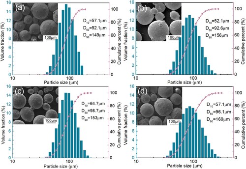
Table 1. Chemical composition of bainitic crossing nose (Wt.%).
Table 2. Chemical composition of depositing materials (Wt.%).
The L-DED system contains a YLS-6000 fibre laser with a wavelength of 1060 nm, a KUKA 6-axis robot, a HUST III powder feeder, and a powder feed nozzle. During L-DED process, the rectangular laser beam with the size of 12 mm × 2 mm was conducted to irradiate and melt the pre-set powders, during which pure argon was used as the carrier and shielding gas. After optimisation of the process parameters, on the one hand, the repairing deposits with the dimension of 120 mm × 70 mm × 10 mm were fabricated on the surface of the full-scale bainitic crossing nose for microstructure and mechanical properties analyses, on the other hand, the repairing deposits with the same thickness were prepared on the cylindrical rail substrates with a diameter of 56 mm for rolling-sliding tests. The optimised experimental parameters for depositing different materials by L-DED are shown in .
Table 3. Experimental parameters for depositing different materials by L-DED.
2.2. Microstructure and mechanical properties analyses
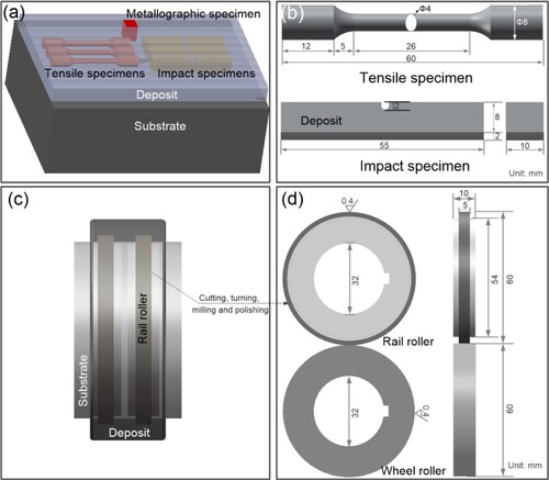
shows the sampling schematic and final dimensions of metallographic, mechanical properties and rolling-sliding specimens. As shown in (a), the metallographic specimens, including deposits and substrate, were cut along the cross-section of repaired crossing noses, for microstructure and microhardness characterisation. The tensile and impact specimens were cut along the longitudinal direction of the repaired crossing noses, where the tensile specimens included only the deposits and impact specimens consisted of both deposits and substrate, as shown in (b). Besides, the rail and wheel rollers were obtained by a series of machining processes from the deposited cylindrical rail substrates and standard CL60 wheel, as shown in (c). The final dimensions of rolling-sliding specimens are shown in (d), and their surface roughness is about 0.4 μm.
Figure 2. Sampling schematic (a, c) and final dimensions (b, d) of different specimens: (a, b) metallographic and mechanical properties specimens, (c, d) rolling-sliding specimens.
After grinding and polishing, on the one hand, the metallographic specimens were etched by a mixture (25 mL HNO3 + 5 mL HCl + 6 g FeCl3 + 50 mL deionised water) to obtain the SEM specimens, on the other hand, the metallographic specimens were electrochemically polished using a mixture of 10% perchloric acid and 90% ethanol to obtain the EBSD specimens. The microscopic morphologies, crystallographic characteristics and compositional distributions of different deposits were characterised by a SEM (FEI Zeiss Gemini 300) equipped with an EBSD detector and an EDS detector. After grinding 3-mm-diameter discs to 30–40 μm in thickness, the TEM specimens were further thinned by a precise ion beam thinner (PIPS II 695, Gatan). The nano-scale microstructure and nanoprecipitates were observed by FEI TecnaiG2-F30 TEM system equipped with an EDS detector.
The microhardness of the repaired crossing noses with different deposits was measured by Vickers-1000 microhardness tester along the depth direction at 1.96 N with a dwell time of 20 s. The tensile properties tests were conducted according to the Chinese standard GB/T228.1-2010 using Shimadzu AG-100kN universal material testing machine with the loading rate of 1 mm/min, and the fracture morphologies were characterised by the SEM. The Charpy impact tests were conducted on NI 500F impact testing machine, in which the maximum hammer speed of 5.3 m/s and testing temperature of 20°C was adopted. The tensile and impact tests were repeated for three times.
The rolling-sliding tests were carried out on the MJP-30A rolling-sliding testing machine, and the testing parameters were as follows: the contact stress was up to 1500 MPa, the creep rate was 2%, the rotate speed was 600 r/min, and the cycling number was 72,000 rpm. The weight difference between the rail rollers before and after tests was weighed to calculate the mass wear rate (μg/m). Besides, the longitudinal cross-section morphologies of rail rollers after tests were characterised by SEM to evaluate the contact fatigue damage behaviours of different specimens. The rolling-sliding tests were repeated for two times.
3. Results
3.1. Microstructural characterisation
The microstructural characteristics of 420SS, Stellite 6, 17-4PH and 18Ni300 deposits are given in , respectively. (a) shows the SEM picture of the 420SS deposit, whereby dendritic solidification microstructure can be observed therein. According to inverse pole figure (IPF) colour map with grain boundaries (GB, ≥10°) in (b), the dendritic microstructure is filled with martensitic needles and laths, which have obvious crystal orientation of <100>. As widely reported (Carter et al. Citation2014; Suryawanshi, Prashanth, and Ramamurty Citation2017; Zou et al. Citation2018), this preferential growth direction is common in laser processing. The average grain size of the 420SS deposit is 2.1 μm, which are the smallest among the four deposits. As observed from the phase distribution picture in (c), the 420SS deposit is mainly composed of martensite and a small amount of austenite (0.4%). The geometrically necessary dislocation (GND) density map of 420SS deposit is given in (d), and a high GND density of 1.723 × 10¹⁵/m2 was formed therein. Moreover, granular carbide particles rich in Cr and Mn with a size of about 65 nm were observed in the EDS distribution diagram characterised by TEM, as shown in (e).
Figure 3. Microstructural characteristics of the 420SS deposit: (a) SEM picture, (b) Inverse pole figure (IPF) colour map with grain boundaries (GB, ≥ 10°), (c) Phase distribution picture, (d) GND map, (e) EDS mapping analysis of nanoprecipitates.
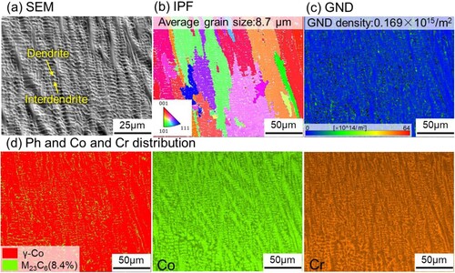
As illustrated by the SEM picture in (a), the Stellite 6 deposit also shows dendritic microstructures, accompanied by net-like eutectics distributed in interdendrites. According to the IPF and GND maps in (b,c), the matrix phase not only has a large average grain size, about 8.7 μm, but also has a low GND density of 0.169 × 10¹⁵/m2. As shown in the phase distribution picture and the element distribution of Co and Cr in (d), the matrix is γ-Co phase, and net-like eutectics in interdendrites are Cr-rich M23C6 (8.4 vol.%).
Figure 4. Microstructural characteristics of the Stellite 6 deposit: (a) SEM picture, (b) IPF colour map with GB (≥10°), (c) GND map, (d) Phase distribution picture and the element distribution of Co and Cr.
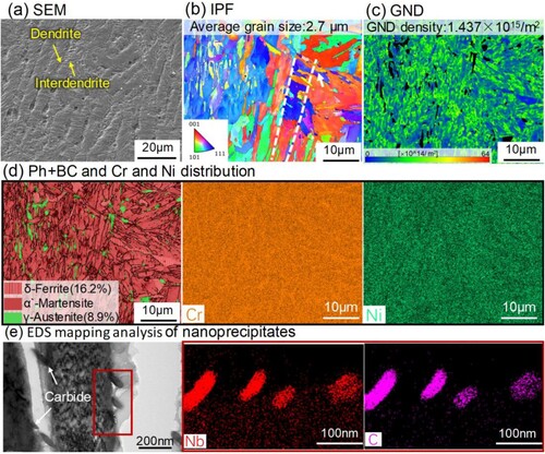
As shown in the SEM picture and IPF map in (a,b), the solidification microstructure of 17-4PH deposit consists of multiple columnar dendrites, which can be crossed by martensite laths with the average grain size of 2.7 μm. According to the GND map in (c), the GND density of the 17-4PH deposit is 1.437 × 10¹⁵/m2. Moreover, (d) shows the band contrast and phase distribution picture with GB (≥10°) and the element distribution of Cr and Ni, in which the 17-4PH deposit consists of the martensite, retained austenite (8.9 vol.%) and vermicular grains (16.2 vol.%) with brighter contrast. The element distribution maps show that the vermicular grains are rich in Cr but poor in Ni, which are identified as δ-Ferrite (D. Guo et al. Citation2020), the main causative factor for microcrack formation under external forces (Li et al. Citation2022; Schönbauer et al. Citation2021). Fortunately, the massive austenite can trigger the transformation-induced plasticity effects to increase the ductility of the 17-4PH deposit. (e) shows the TEM bright field picture and the EDS mapping analysis, whereby rod like NbC particles with a size of about 80 nm distributed at the boundary of austenite and martensite are observed clearly.
Figure 5. Microstructural characteristics of the 17-4PH deposit: (a) SEM picture, (b) IPF colour map with GB (≥10°), (c) GND map, (d) Band contrast and phase distribution picture with GB (≥ 10°) and the element distribution of Cr and Ni, (e) EDS mapping analysis of nanoprecipitates.
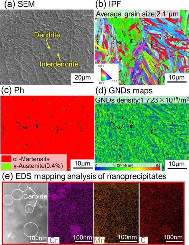
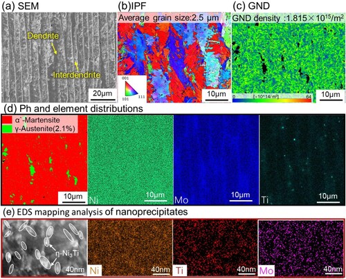
According to the SEM picture and IPF map of 18Ni300 deposit in (a,b), the martensite laths superimposed on the dendritic solidification microstructure can be observed clearly therein, which is consistent with 17-4PH deposit, but with finer grain size. Moreover, as shown in the GND map in (c), the 18Ni300 deposit also has extremely high GND density, which is 1.815 × 10¹⁵/m2. (d) shows the phase distribution picture and corresponding element distributions, whereby the 18Ni300 deposit consists of a small amount of retained austenite in addition to the main martensite. The retained austenite is mainly distributed at the dendrite boundary, which could be attributed to micro-segregations of Ni therein. Moreover, micro-segregations of Ti and Mo are also visible therein, indicating that the supersaturation required to trigger Ni-Ti(Mo)-based nanoprecipitate increased at the dendrite boundaries (Allam et al. Citation2020). According to the EDS mapping analysis characterised by TEM in (e), the 18Ni300 deposit is distributed with massive nano-precipitates, mainly composed of Ni, Mo and Ti elements, which were triggered by the IHT of multi-layer thermal cycles in L-DED (B. Zhu et al. Citation2023).
Figure 6. Microstructural characteristics of the 18Ni300 deposit: (a) SEM picture, (b) IPF colour map with GB (≥10°), (c) GND map, (d) Phase distribution picture and corresponding element distributions, (e) EDS mapping analysis of nanoprecipitates.
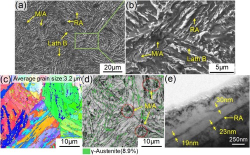
The microstructural characteristics of the bainitic crossing nose are given in , respectively. According to the SEM pictures in (a,b), the bainitic substrate consists of lath bainitic ferrite (lath B), film retained austenite (RA), and blocky martensite/residual austenite islands (M/A). However, the M/A, interspersed between lath B, can cause microcracks initiated at the interface and propagated along the boundary of M/A (Fan et al. Citation2022). The IPF map in (c) reveals that the average grain size of the substrate without strong textures is 3.2 μm. (d) shows the band contrast map overlapped with retained austenite (in green), in which massive RA (8.9 vol.%) can be observed in the forms of blocky islands and lath films. Moreover, the further microstructural characterisation by TEM is given in (e), in which the fine-film RA with the thickness of 20–30 nm is observed between the lath B, which may not be observed by EBSD due to that its scan step size is 100 nm. Therefore, the volume fraction of RA in the substrate is certainly more than 8.9%, which can account for the good toughness (W. J. Wang et al. Citation2016b).
Figure 7. Microstructural characteristics of the untreated bainitic crossing nose: (a, b) SEM pictures, (c) IPF colour map with GB (≥10°), (d) Band contrast map overlapped with retained austenite (in green), (e) Bright field TEM picture.
3.2. Mechanical properties
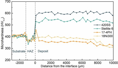
shows the microhardness distributions along the depth direction of different repaired crossing noses. The microhardness of 420SS and Stellite 6 deposits is basically stable at 603 ± 10 HV0.2 and 538 ± 13 HV0.2, which are about 30% and 20% higher than the substrate. Besides, the microhardness of 18Ni300 and 17-4PH deposits first increases gradually along the depth direction and then remains at relatively stable values, which are essentially comparable to or slightly less than that of the substrate, while a sudden increase in microhardness occurs at the interface in 20Mn2SiCrMo/17-4PH FGM due to the formation of carbides in the microstructural transition zone (Zhang, He, and Wang Citation2022). The main reason for the non-uniform distribution of microhardness is that the 18Ni300 and 17-4PH deposits are subjected to IHT during multi-layered L-DED process (B. Zhu et al. Citation2023), and apparently in situ heat treatment has a greater influence on the microhardness of 18Ni300 deposit than that of 17-4PH deposit. In addition, the microhardness in HAZs of all specimens is reduced by about 10% compared to that of the substrate, which is mainly due to the carbide precipitation caused by the self-tempering effect therein in multi-layered L-DED process (Zhang, He, and Wang Citation2022).
Figure 8. Microhardness distributions along the depth direction of different repaired bainitic crossing noses.
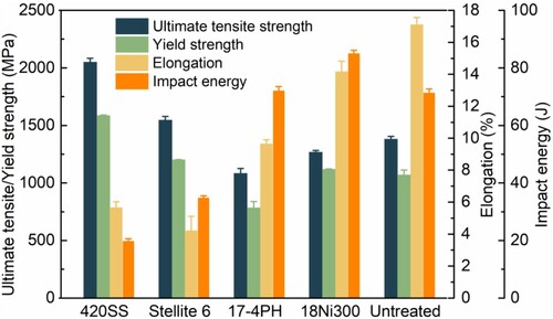
Uniaxial tensile and impact tests were carried out to compare the mechanical properties of deposited and untreated crossing noses in this part, and the results are shown in . Although the 420SS and Stellite 6 deposits both can offer high yield strength values, 1586 ± 4 MPa, 1203 ± 1 MPa, much higher than that of the untreated crossing nose (1071 ± 40 MPa), the elongation and impact energy of 420SS and Stellite 6 deposits are only 5.5 ± 0.5% and 19.75 ± 0.84 J, 4 ± 1% and 34.84 ± 0.75 J, lower than that of the untreated crossing nose (17 ± 1% and 71.34 ± 1.34 J). On the contrary, the 17-4PH deposit possesses satisfactory toughness with the impact energy of 72.08 ± 1.43 J, but its yield strength is only 785 ± 54 MPa, which cannot satisfy the repaired criterion of deposited crossing noses to resist plastic deformation. Fortunately, the 18Ni300 deposit possesses a yield strength of 1120 ± 2 MPa together with the elongation of 14 ± 0.5% and the impact energy of 85.05 ± 1.05 J, which achieves an excellent strength-toughness combination, even showing better mechanical properties than those of the untreated crossing nose.
Figure 9. Tensile and impact properties of different deposits and untreated crossing noses.
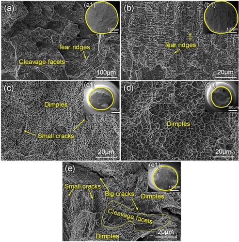
Furthermore, shows tensile fracture surfaces of different deposits and untreated crossing nose, with full views of the fracture inset in the top-right corner ((a1–e1)). (a,b) shows the fracture surfaces of 420SS and Stellite 6 deposits, from which almost no necking phenomena can be observed in the overall morphologies. Moreover, a mixed fracture with cleavage facets and tear ridges is visible in the magnifying morphology of 420SS deposit, and all fine tear ridges are visible in the magnifications of the Stellite 6 deposit, which indicates the typical brittle fracture morphologies therein. In contrast, ductile dimples are predominant in the fracture surfaces of 17-4PH and 18Ni300 deposits, accompanied by obvious necking phenomena, showing the typical ductile fracture morphologies, as shown in (c,d). However, some small cracks caused by the large amounts of ferrite are observed in the 17-4PH deposit, which agrees well with the low yield strength and elongation therein. As shown in (e), the bainitic substrate shows a mixed fracture mode, whereby both the small dimples and cleavage facets are visible on the fracture surface.
Figure 10. Tensile fracture surfaces of different specimens: (a–d) 420SS, Stellite 6, 17-4PH and 18Ni300 deposits, (e) untreated crossing nose, in which the (a1–e1) graphs are the full views of the corresponding tensile fracture surfaces.
3.3. Wear properties and contact fatigue damage behaviours
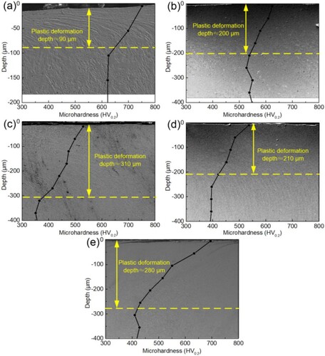
The rolling-sliding tests were carried out to compare and analyse the wear properties and contact fatigue damage behaviours of the deposited and untreated crossing noses in this section, and the results are shown in . As shown in , the mass wear rate of 420SS, 17-4PH and 18Ni300 rail rollers is 9.2 ± 1.2 μg/m, 35.6 ± 2.5 μg/m and 26.2 ± 1.6 μg/m, reduced by 86.7%, 48.6% and 62.2% compared with that of the untreated rail roller (69.3 ± 3.7 μg/m), while the mass wear rate of the Stellite 6 rail roller is 90.5 ± 2.5 μg/m, much higher than that of the untreated rail roller. gives the plastic deformation morphologies and corresponding microhardness distributions of different rail rollers after tests, whereby the obvious plastic deformation accompanied by the microhardness increment is observed in all specimens due to that the contact stress is much higher than shakedown limits. Moreover, the plastic deformation depth of 420 SS, Stellite 6, 17-4PH and 18Ni300 deposited and untreated rail rollers is about 90, 200, 310, 210, 280 μm, which is inversely correlated with the yield strength of the materials. According to the literature (Kumar et al. Citation2019), the localised plastic deformation at the impacted point usually leads to shelling and lipping damage to the crossing nose rails, which would increase the impact forces on the rails in their next service. Therefore, as far as the wear and the plastic deformation resistance are concerned, the Stellite 6 and 17-4PH are not promising depositing materials for repairing the crossing noses by L-DED.
Figure 11. Mass wear rate of deposited and untreated rail rollers.
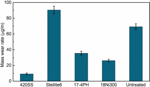
Figure 12. The plastic deformation morphologies and corresponding microhardness distributions of deposited rail rollers with: (a) 420SS, (b) Stellite 6, (c) 17-4PH and (d) 18Ni300 deposits, and untreated rail rollers (e).
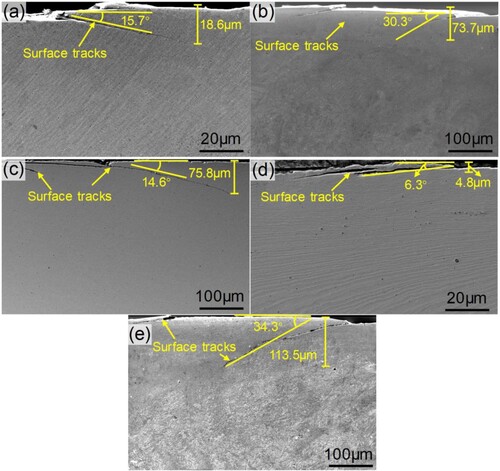
Moreover, shows the cracks propagation morphologies of deposited and untreated rail rollers, from which fatigue cracks that propagate from the surface to the subsurface can be observed clearly in all specimens. The crack propagation angle and depth of 420SS, Stellite 6, 17-4PH and 18Ni300 rail rollers are 15.5° and 18.6 μm, 30.3° and 73.7 μm, 14.6° and 73.8 μm, 6.3° and 4.8 μm, which are all much lower than those of the untreated crossing nose (34.3° and 113.5 μm), where 18Ni300 rail roller shows the best RCF resistance with the lowest crack propagation angle and depth. Therefore, all findings reveal that 18Ni300 is the most promising depositing material for repairing the bainitic crossing noses by L-DED.
Figure 13. The cracks propagation morphologies of deposited rail rollers with: (a) 420SS, (b) Stellite 6, (c) 17-4PH and (d) 18Ni300 deposits, and untreated rail rollers (e).
4. Discussion
4.1. Influence mechanisms of microstructure on the mechanical properties
4.1.1. Strengthening mechanisms of different materials
As far as the strengthening mechanisms of steels are concerned, the yield strength of Fe-based deposits is mainly contributed by lattice friction stress (σ0 = 50 MPa (Zhao et al. Citation2022)), grain boundary and dislocation strengthening (ΔσG), solid solution strengthening (Δσss) and precipitation strengthening (Δσp). This is expressed in the terms of the yield strength (Δσy) as EquationEq. (1)(1)
(1) , whereby ΔσG and Δσss are added in Pythagoras’s rule.
(1)
(1) First, the grain size and dislocation density determine the effect of grain boundary and dislocation strengthening according to the Hall–Petch mechanism, whereby the increased yield strength of ΔσG follows Equation (2):
(2)
(2) where the k is the Hall–Petch constant, estimated as 300 MPa μm−2 in the lath martensite (17-4PH and 18Ni300 deposits) and 572 MPa μm−2 (Yan et al. Citation2020) in the 420SS deposit, dMart is the statistical size of martensite as quantified from the EBSD results, M is the Taylor factor (estimated as 3 for BCC crystal structure of iron (Mazaheri, Kermanpur, and Najafizadeh Citation2015)), G is the shear modulus (taken as 72 GPa (Mei et al. Citation2022)), b is the Burgers vector (taken as 0.25 nm (Galindo-Nava, Rainforth, and Rivera-Díaz-del-Castillo Citation2016)), and the dislocation density ρd can also be measured from the EBSD results.
Second, solid solution strengthening arises from the interaction of solute atoms and dislocations which is determined by the atomic concentration of solutes dissolved in the parent phase. Generally, the solid solution strengthening contribution (Δσss) can be expressed by the following empirical formula (Young and Bhadeshia Citation1995):
(3)
(3) where βi is the strengthening coefficient of element i, and
is the atom fraction of substitutional element i in the α matrix. The βi-values obtained from previous studies (Lu, Xu, and van der Zwaag Citation2014) and
-values measured by TEM-EDS of different elements are displayed in .
Table 4. Solid solution strengthening constant and EDS analyses results of chemical composition in different deposits (at.%).
Lastly, precipitates formed in all Fe-based deposits due to the IHT in multi-layer L-DED, can also resist the movement of dislocations. The precipitation strengthening contribution (Δσp) follows the Orowan bowing mechanism (Schnitzer, Zinner, and Leitner Citation2010):
(4)
(4) where G, b, and have been defined above, the Poisson’s ratio v is 0.3 (Galindo-Nava and Rivera-Díaz-del-Castillo Citation2015), and L is to the spacing of precipitates, and D represent the equivalent spherical diameter of precipitates.
Consequently, the measured yield strength and predicted results of 420SS, 17-4PH and 18Ni300 specimens are compared in . The predicted results of the 420SS and 18Ni300 specimens are close to the measured values, while that of the 17-4PH specimen is about 110 MPa higher than the measured value. The main reason is that the above calculations were carried out assuming a fully martensitic matrix in the deposits, while there is a high content of softened austenite in 17-4PH.
Table 5. Measured yield strength and predicted results of 420SS, 17-4PH and 18Ni300 specimens.
As far as the Co-based alloy is concerned, the precipitation strengthening is the main strengthening method (Z. Yang et al. Citation2022b), and the massive carbides (8.4 vol.%) in Stellite 6 deposit can account for the high Δσp. Moreover, the high atomic concentration of solutes dissolved in the Stellite 6 deposit could induce the solid solution strengthening contribution. However, due to the large grain size and low dislocation density, the grain boundary strengthening contribution of Stellite 6 deposit is much less than other deposits.
4.1.2. Toughening mechanisms of different materials
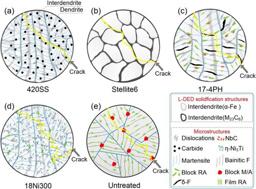
compares the toughening mechanism of deposited and untreated specimens by combining with the schematic diagram of microstructure. As shown in (a), the 420SS specimen consists of fine martensite (martensitic needles and laths) and some carbides, where the martensite dissolved with a large amount of C element (0.86 at.%) has high internal stress and poor plasticity, making the impact toughness weakened therein. As shown in (b), the Stellite 6 deposit is mainly composed of carbides and γ-Co, whereby the microcracks tended to initiate and propagate along the interface of matrix and net-like carbides due to their strain incompatibility, resulting in the unsatisfactory impact toughness therein. In the 17-4PH and 18Ni300 deposits, the lath martensite matrix with high-density dislocation has higher toughness compared to the acicular martensite in 420SS deposit. Meanwhile, the retained austenite with high mechanical stability is present between the martensitic laths, which could relieve stress concentration at the crack tip and inhibit crack propagation, resulting in the excellent impact toughness of 17-4PH and 18Ni300 deposits, as shown in (c,d). However, 17-4PH deposit with more austenite had lower toughness than 18Ni300 deposit, and the main reasons are that: on the one hand, the brittle phase (δ-Ferrite) in 17-4PH deposit could accelerate crack initiation and propagation therein under external forces, on the other hand, the fine martensitic laths and nanoprecipitates in 18Ni300 deposit made the crack propagation path more tortuous. As shown in (e), in the untreated bainitic crossing nose, although the large amount of film and block austenite could contribute to the comparatively good impact toughness, the blocky M/A islands accompanied by stress concentration would perform as preferential sites for initiating cleavage fracture to accelerate crack propagation, resulting in the worse toughness than that of the 18Ni300 deposit.
Figure 14. The schematic diagram of microstructure and crack propagation behaviours in response to the impact load of: (a) 420SS, (b) Stellite 6, (c) 17-4PH, (d) 18Ni300 deposits, and (e) untreated crossing nose.
4.2. Influence mechanisms of the wear and RCF resistance
The wear resistance of the rails is mainly determined by the microstructure and work-hardenability of the rail materials (Robles Hernández et al. Citation2011; Roy et al. Citation2018). The RCF resistance is an intrinsic property that depends on the grain boundaries and the shakedown limits of the steel materials (Robles Hernández et al. Citation2011), where the shakedown limits are determined by the yield strength of the materials (Connolly and Yu Citation2021; Ringsberg et al. Citation2005). Besides, there is a competitive relationship between wear and fatigue resistance (H. H. Wang et al. Citation2023).
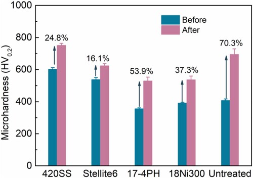
compares the microhardness increment of deposited and untreated rail rollers, from which the microhardness of all rail rollers was increased after the tests. After work-hardening during the rolling-sliding tests, the microhardness of the 420SS deposit was highest with about 751 HV0.2, which is the main reason that the 420SS rail roller had the optimum wear resistance. The coarse microstructure and the poor work-hardenability of the Stellite 6 deposit caused the worst wear resistance of Stellite 6 rail roller. Moreover, the work-hardenability of the 17-4 PH deposit was superior than that of other deposits due to the transformation-induced plasticity (TRIP) effects of the austenite (Abareshi and Emadoddin Citation2011) therein, making the 17-4 PH rail roller with low initial microhardness possessing satisfactory wear resistance. However, although the untreated rail roller also possessed excellent work-hardenability, the wear resistance is not favourable as that of the 420SS rail roller or even the 17-4 PH rail roller. According to the previous analysis, the main reason is that the accumulated microcracks (as shown in (e)) on the surface of the untreated rail roller could further result in the shelling damage (Roy et al. Citation2018), making the wear rate increased therein. Last but not least, the 18Ni300 rail roller was secondly only to the 420SS rail roller in terms of wear resistance, mainly due to the fact that the fine martensite laths with massive ultrafine nanoprecipitates and small amount of austenite can make the deposit strong enough as well as a certain work-hardenability.
Figure 15. Comparison microhardness increment of deposited and untreated rail rollers before and after the tests.
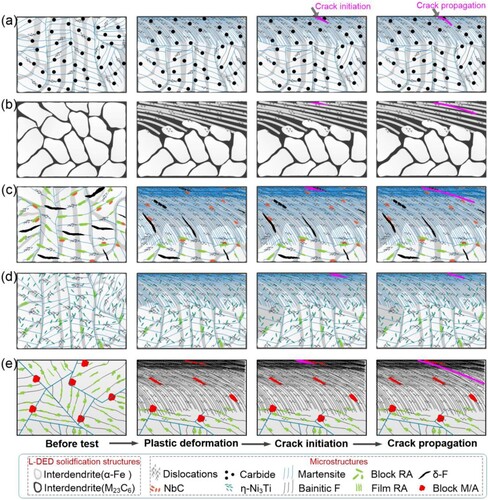
constructs the schematic diagram of RCF crack initiation and propagation of different materials under cyclic rolling contact loads. As shown in , all specimens first underwent accumulated plastic deformation until the surface reached the stable ratcheting state, which then resulted in RCF cracks initiating at the grain boundaries where stresses were more concentrated (He et al. Citation2015). In 420SS specimen, the excellent wear resistance slowed down the removal of material with crack initiation, so RCF cracks were more likely to propagated in short depths and large angles on the surface of the 420SS, as shown in (a). As shown in (b–e), the RCF cracks could easily initiate and propagate along the interface of the large brittle phase (carbides, δ-ferrite and M/A) and the matrix phase in Stellite 6, 17-4PH and untreated specimens. In contrast, the 18Ni300 specimen has the best fatigue resistance, the main reason is that: first, the single-phase microstructure reduces the stress concentration at the grain boundaries; then, the ultrafine nanoprecipitates in the deposit can be beneficial to improve the shakedown limit, as shown in (d).
Figure 16. Schematic diagram of RCF crack initiation and propagation of deposited rail rollers with: (a) 420SS, (b) Stellite 6, (c) 17-4PH and (d) 18Ni300 deposits, and untreated rail rollers (e).
5. Conclusions
In this work, 20Mn2SiCrMo bainitic crossing noses were repaired by depositing 420SS, Stellite 6, 17-4PH and 18Ni300 alloys on the rail surfaces to form functionally graded materials (FGM) using laser directed energy deposition (L-DED) technology. The microstructural characteristics, mechanical properties, wear properties and contact fatigue damage behaviours of repaired crossing noses were evaluated systematically to determine the promising depositing material for repairing the bainitic crossing noses by L-DED. On this basis, strengthening and toughening mechanisms of different microstructure characteristics on the different deposits were analysed, and their influences mechanisms on the wear and RCF resistance were discussed comparatively. The main conclusions are shown below:
All of the deposits show dendritic solidification microstructure, accompanied by obvious crystal orientation of <100>. However, the phase, substructure and solubility of elements of the deposits are different. The 420SS deposit is mainly composed of high-carbon acicular and lath martensite with the finest grain size, as well as some carbides. The Stellite 6 deposit consists of γ-Co phase and net-like eutectic carbides distributed in interdendrites. The 17-4PH deposit consists of low-carbon lath martensite, vermicular δ-ferrite (16.2 vol.%), austenite (8.9 vol.%) and a small amount of rod-like carbides. The 18Ni300 deposit consists of low-carbon lath martensite, austenite (2.1 vol.%) and massive nanoprecipitates. Besides, the bainitic crossing nose is mainly composed of lath bainitic ferrite, film and blocky retained austenite, and blocky martensite/residual austenite islands.
The impact energy of 420SS and Stellite 6 deposits is only ∼19.75 J and ∼34.84 J due to high carbon solid solution, which is much lower than that of substrates (∼71.34 J). Besides, the 17-4PH deposit possesses low yield strength of ∼785 MPa, which is also lower than that of substrates (∼1071 MPa), thus resulting in poor resistance to plastic deformation. Fortunately, the 18Ni300 deposit possesses a yield strength of ∼1120 MPa together with an impact energy of ∼85.05 J, which achieves an excellent strength-toughness combination, even better than those of substrates. The high-density dislocations and grain refinement strengthening, high-alloyed solution strengthening and precipitation strengthening contribute to the high strength of 18Ni300 deposit, while its excellent toughness originates from the dislocation substructure in low-carbon lath martensite, retained austenite, ultrafine nanoprecipitates.
The 420SS, 17-4PH and 18Ni300 deposits all show much better wear and RCF resistance than the untreated crossing nose, whereas the wear resistance of the Stellite 6 deposit is worse than that of the substrate. Especially, the 18Ni300 deposit with satisfactory wear resistance has better fatigue resistance than that of the 420SS and 17-4PH deposits. The wear and RCF resistance of 18Ni300 deposit is enhanced to 2.7 times and 23.6 times as much as those of substrates. The massive ultrafine nanoprecipitates and a small amount of austenite make the 18Ni300 deposit strong enough as well as a certain work-hardenability, ensuring good wear resistance therein; the significant RCF resistance originates from the reduced stress concentration at the grain boundaries and improved shakedown limit. All findings reveal that 18Ni300 is the most promising depositing material for repairing the bainitic crossing noses by L-DED.
Disclosure statement
No potential conflict of interest was reported by the author(s).
Funding
This work was supported by the National Natural Science Foundation of China [grant number 52005197], the Postdoctoral Science Foundation of China [grant number 2020M682408], the National Postdoctoral Program for Innovative Talents [grant number BX20200137], the National Key Research and Development Program of China [grant number 2016YFB1102600] and the Science and Technology R&D Project of China Railway Corporation [grant number K2018G054].
Data availability statement
The raw data required to reproduce these findings cannot be shared at this time as the data also forms part of an ongoing study.
References
- Abareshi, M., and E. Emadoddin. 2011. “Effect of Retained Austenite Characteristics on Fatigue Behavior and Tensile Properties of Transformation Induced Plasticity Steel.” Materials & Design 32 (10): 5099–5105. https://doi.org/10.1016/j.matdes.2011.06.018.
- Allam, T., K. G. Pradeep, P. Köhnen, A. Marshal, J. H. Schleifenbaum, and C. Haase. 2020. “Tailoring the Nanostructure of Laser Powder bed Fusion Additively Manufactured Maraging Steel.” Additive Manufacturing 36. https://doi.org/10.1016/j.addma.2020.101561.
- Carter, L. N., C. Martin, P. J. Withers, and M. M. Attallah. 2014. “The Influence of the Laser Scan Strategy on Grain Structure and Cracking Behaviour in SLM Powder-bed Fabricated Nickel Superalloy.” Journal of Alloys and Compounds 615:338–347. https://doi.org/10.1016/j.jallcom.2014.06.172.
- Clare, A., O. Oyelola, J. Folkes, and P. Farayibi. 2012. “Laser Cladding for Railway Repair and Preventative Maintenance.” Journal of Laser Applications 24 (3): 032004. https://doi.org/10.2351/1.4710578.
- Connolly, D. P., and H. S. Yu. 2021. “A Shakedown Limit Calculation Method for Geogrid Reinforced Soils Under Moving Loads.” Geotextiles and Geomembranes 49 (3): 688–696. https://doi.org/10.1016/j.geotexmem.2020.11.009.
- Fan, Y., X. Gui, M. Liu, X. Wang, B. Bai, and G. Gao. 2022. “Effect of Microstructure on Wear and Rolling Contact Fatigue Behaviors of Bainitic/Martensitic Rail Steels.” Wear 508–509:204474. https://doi.org/10.1016/j.wear.2022.204474.
- Franklin, F. J., G. J. Weeda, A. Kapoor, and E. J. M. Hiensch. 2005. “Rolling Contact Fatigue and Wear Behaviour of the Infrastar two-Material Rail.” Wear 258 (7-8): 1048–1054. https://doi.org/10.1016/j.wear.2004.03.054.
- Galindo-Nava, E. I., W. M. Rainforth, and P. E. J. Rivera-Díaz-del-Castillo. 2016. “Predicting Microstructure and Strength of Maraging Steels: Elemental Optimisation.” Acta Materialia 117:270–285. https://doi.org/10.1016/j.actamat.2016.07.020.
- Galindo-Nava, E. I., and P. E. J. Rivera-Díaz-del-Castillo. 2015. “A Model for the Microstructure Behaviour and Strength Evolution in Lath Martensite.” Acta Materialia 98:81–93. https://doi.org/10.1016/j.actamat.2015.07.018.
- Guo, D., C. T. Kwok, L. M. Tam, D. Zhang, and X. Li. 2020. “Hardness, Microstructure and Texture of Friction Surfaced 17-4PH Precipitation Hardening Stainless Steel Coatings with and Without Subsequent Aging.” Surface and Coatings Technology 402:126302. https://doi.org/10.1016/j.surfcoat.2020.126302.
- Guo, H.-M., Q. Wang, W.-J. Wang, J. Guo, Q.-Y. Liu, and M.-H. Zhu. 2015. “Investigation on Wear and Damage Performance of Laser Cladding Co-Based Alloy on Single Wheel or Rail Material.” Wear 328–329:329–337. https://doi.org/10.1016/j.wear.2015.03.002.
- He, C. G., Y. B. Huang, L. Ma, J. Guo, W. J. Wang, Q. Y. Liu, and M. H. Zhu. 2015. “Experimental Investigation on the Effect of Tangential Force on Wear and Rolling Contact Fatigue Behaviors of Wheel Material.” Tribology International 92:307–316. https://doi.org/10.1016/j.triboint.2015.07.012.
- Hiensch, E. J. M., F. J. Franklin, J. C. O. Nielsen, J. W. Ringsberg, G. J. Weeda, A. Kapoor, and B. L. Josefson. 2003. “Prevention of RCF Damage in Curved Track Through Development of the INFRA-STAR Two-Material Rail.” Fatigue & Fracture of Engineering Materials & Structures 26 (10): 1007–1017. https://doi.org/10.1046/j.1460-2695.2003.00663.x.
- Kanishka, K., and B. Acherjee. 2023. “A Systematic Review of Additive Manufacturing-Based Remanufacturing Techniques for Component Repair and Restoration.” Journal of Manufacturing Processes 89:220–283. https://doi.org/10.1016/j.jmapro.2023.01.034.
- Kumar, A., S. K. Makineni, A. Dutta, C. Goulas, M. Steenbergen, R. H. Petrov, and J. Sietsma. 2019. “Design of High-Strength and Damage-Resistant Carbide-Free Fine Bainitic Steels for Railway Crossing Applications.” Materials Science and Engineering: A 759:210–223. https://doi.org/10.1016/j.msea.2019.05.043.
- Lai, Q., R. Abrahams, W. Yan, C. Qiu, P. Mutton, A. Paradowska, and M. Soodi. 2017. “Investigation of a Novel Functionally Graded Material for the Repair of Premium Hypereutectoid Rails Using Laser Cladding Technology.” Composites Part B: Engineering 130:174–191. https://doi.org/10.1016/j.compositesb.2017.07.089.
- Lai, Q., R. Abrahams, W. Yan, C. Qiu, P. Mutton, A. Paradowska, M. Soodi, and X. Wu. 2019. “Influences of Depositing Materials, Processing Parameters and Heating Conditions on Material Characteristics of Laser-Cladded Hypereutectoid Rails.” Journal of Materials Processing Technology 263:1–20. https://doi.org/10.1016/j.jmatprotec.2018.07.035.
- Li, K., J. Zhan, T. Yang, A. C. To, S. Tan, Q. Tang, H. Cao, and L. E. Murr. 2022. “Homogenization Timing Effect on Microstructure and Precipitation Strengthening of 17–4PH Stainless Steel Fabricated by Laser Powder bed Fusion.” Additive Manufacturing 52:102672. https://doi.org/10.1016/j.addma.2022.102672.
- Lu, Q., W. Xu, and S. van der Zwaag. 2014. “The Design of a Compositionally Robust Martensitic Creep-Resistant Steel with an Optimized Combination of Precipitation Hardening and Solid-Solution Strengthening for High-Temperature use.” Acta Materialia 77:310–323. https://doi.org/10.1016/j.actamat.2014.06.007.
- Mazaheri, Y., A. Kermanpur, and A. Najafizadeh. 2015. “Strengthening Mechanisms of Ultrafine Grained Dual Phase Steels Developed by New Thermomechanical Processing.” ISIJ International 55 (1): 218–226. https://doi.org/10.2355/isijinternational.55.218.
- Mei, X., Y. Yan, H. Fu, X. Gao, S. Huang, and L. Qiao. 2022. “Effect of Aging Temperature on Microstructure Evolution and Strengthening Behavior of L-PBF 18Ni(300) Maraging Steel.” Additive Manufacturing 58:103071. https://doi.org/10.1016/j.addma.2022.103071.
- Meng, L., B. Zhu, Q. Hu, X. Zeng, and D. Wang. 2021. “Laser-induction Hybrid Cladding of Different Coatings on Rail Surface: Microstructure, Wear Properties and Contact Fatigue Behaviors.” Applied Surface Science 566:150678. https://doi.org/10.1016/j.apsusc.2021.150678.
- Ringsberg, J. W., F. J. Franklin, B. L. Josefson, A. Kapoor, and J. C. O. Nielsen. 2005. “Fatigue Evaluation of Surface Coated Railway Rails Using Shakedown Theory, Finite Element Calculations, and Lab and Field Trials.” International Journal of Fatigue 27 (6): 680–694. https://doi.org/10.1016/j.ijfatigue.2004.11.002.
- Robles Hernández, F. C., N. G. Demas, K. Gonzales, and A. A. Polycarpou. 2011. “Correlation Between Laboratory Ball-on-Disk and Full-Scale Rail Performance Tests.” Wear 270 (7-8): 479–491. https://doi.org/10.1016/j.wear.2011.01.001.
- Roy, T., Q. Lai, R. Abrahams, P. Mutton, A. Paradowska, M. Soodi, and W. Yan. 2018. “Effect of Deposition Material and Heat Treatment on Wear and Rolling Contact Fatigue of Laser Cladded Rails.” Wear 412-413:69–81. https://doi.org/10.1016/j.wear.2018.07.001.
- Schnitzer, R., S. Zinner, and H. Leitner. 2010. “Modeling of the Yield Strength of a Stainless Maraging Steel.” Scripta Materialia 62 (5): 286–289. https://doi.org/10.1016/j.scriptamat.2009.11.020.
- Schönbauer, B. M., K. Yanase, M. Chehrehrazi, M. Endo, and H. Mayer. 2021. “Effect of Microstructure and Cycling Frequency on the Torsional Fatigue Properties of 17-4PH Stainless Steel.” Materials Science and Engineering: A 801:140481. https://doi.org/10.1016/j.msea.2020.140481.
- Suryawanshi, J., K. G. Prashanth, and U. Ramamurty. 2017. “Tensile, Fracture, and Fatigue Crack Growth Properties of a 3D Printed Maraging Steel Through Selective Laser Melting.” Journal of Alloys and Compounds 725:355–364. https://doi.org/10.1016/j.jallcom.2017.07.177.
- Wang, W. J., Z. K. Fu, X. Cao, J. Guo, Q. Y. Liu, and M. H. Zhu. 2016a. “The Role of Lanthanum Oxide on Wear and Contact Fatigue Damage Resistance of Laser Cladding Fe-Based Alloy Coating Under Oil Lubrication Condition.” Tribology International 94:470–478. https://doi.org/10.1016/j.triboint.2015.10.017.
- Wang, W. J., Z. K. Fu, J. Guo, Y. Q. Zhang, Q. Y. Liu, and M. H. Zhu. 2016b. “Investigation on Wear Resistance and Fatigue Damage of Laser Cladding Coating on Wheel and Rail Materials Under the Oil Lubrication Condition.” Tribology Transactions 59 (5): 810–817. https://doi.org/10.1080/10402004.2015.1107926.
- Wang, S., J. Ning, L. Zhu, Z. Yang, W. Yan, Y. Dun, P. Xue, P. Xu, S. Bose, and A. Bandyopadhyay. 2022. “Role of Porosity Defects in Metal 3D Printing: Formation Mechanisms, Impacts on Properties and Mitigation Strategies.” Materials Today 59:133–160. https://doi.org/10.1016/j.mattod.2022.08.014.
- Wang, Z. D., G. F. Sun, M. Z. Chen, Y. Lu, S. B. Zhang, H. F. Lan, K. D. Bi, and Z. H. Ni. 2021. “Investigation of the Underwater Laser Directed Energy Deposition Technique for the On-Site Repair of HSLA-100 Steel with Excellent Performance.” Additive Manufacturing 39:101884. https://doi.org/10.1016/j.addma.2021.101884.
- Wang, K., Z. Tan, C. Cheng, B. Gao, G. Gao, R. D. K. Misra, and B. Bai. 2016c. “Effect of Microstructure on the Spalling Damage in a 20Mn2SiCrMo Bainitic Rail.” Engineering Failure Analysis 70:343–350. https://doi.org/10.1016/j.engfailanal.2016.09.011.
- Wang, K., Z. Tan, G. Gao, B. Gao, X. Gui, R. D. Misra, and B. Bai. 2016d. “Microstructure-Property Relationship in Bainitic Steel: The Effect of Austempering.” Materials Science and Engineering: A 675:120–127. https://doi.org/10.1016/j.msea.2016.08.026.
- Wang, H. H., W. J. Wang, Z. Y. Han, Y. Wang, H. H. Ding, R. Lewis, Q. Lin, Q. Y. Liu, and Z. R. Zhou. 2023. “Wear and Rolling Contact Fatigue Competition Mechanism of Different Types of Rail Steels Under Various Slip Ratios.” Wear 522:204721. https://doi.org/10.1016/j.wear.2023.204721.
- Yan, J., H. Song, Y. Dong, W.-M. Quach, and M. Yan. 2020. “High Strength (∼2000 MPa) or Highly Ductile (∼11%) Additively Manufactured H13 by Tempering at Different Conditions.” Materials Science and Engineering: A 773:138845. https://doi.org/10.1016/j.msea.2019.138845.
- Yang, X., C. Li, M. Zhang, Z. Ye, X. Zhang, M. Zheng, J. Gu, H. Zhu, and F. Wang. 2022a. “Study on Tensile and Thermal Fatigue Behaviors of Additively Manufactured Cobalt-Based Alloys Alloying with Al and Ni.” Materials Science and Engineering: A 840:142914. https://doi.org/10.1016/j.msea.2022.142914.
- Yang, Z., S. Wang, L. Zhu, J. Ning, B. Xin, Y. Dun, and W. Yan. 2022b. “Manipulating Molten Pool Dynamics During Metal 3D Printing by Ultrasound.” Applied Physics Reviews 9 (2): 021416. https://doi.org/10.1063/5.0082461.
- Yang, Z., L. Zhu, S. Wang, J. Ning, Y. Dun, G. Meng, P. Xue, P. Xu, and B. Xin. 2021. “Effects of Ultrasound on Multilayer Forming Mechanism of Inconel 718 in Directed Energy Deposition.” Additive Manufacturing 48:102462. https://doi.org/10.1016/j.addma.2021.102462.
- Young, C. H., and H. K. D. H. Bhadeshia. 1995. “Computer Modelling for the Yield Strength of the Mixed Micro-Structures of Bainite and Martensite.” Le Journal de Physique IV 5 (C8): C8-267–C8-272. https://doi.org/10.1051/jp4:1995837.
- Zhang, B., B. He, and H. Wang. 2022. “Microstructural Investigation and Mechanical Performance of Laser Cladding Repaired Bainite Steel with AerMet100 Steel.” Surface and Coatings Technology 440:128498. https://doi.org/10.1016/j.surfcoat.2022.128498.
- Zhao, Z., L. Wang, D. Kong, P. Liu, X. He, X. Ni, L. Zhang, and C. Dong. 2022. “Texture Dependence on the Mechanical Properties of 18Ni300 Maraging Steel Fabricated by Laser Powder Bed Fusion.” Materials Characterization 189:111938. https://doi.org/10.1016/j.matchar.2022.111938.
- Zhu, B., L. Meng, X. Zeng, Q. Hu, X. Liu, G. Xu, and D. Wang. 2023. “Laser Cladding High-Performance Maraging-Steel Coatings on Bainitic Cross Wing Rails Assisted with in-Situ Induction Heating: Microstructure and Performance.” Journal of Materials Processing Technology 313:117886. https://doi.org/10.1016/j.jmatprotec.2023.117886.
- Zhu, L., S. Wang, H. Lu, D. Qi, D. Wang, Z. Yang, J. Ning, et al. 2022. “Investigation on Synergism Between Additive and Subtractive Manufacturing for Curved Thin-Walled Structure.” Virtual and Physical Prototyping 17 (2): 220–238. https://doi.org/10.1080/17452759.2022.2029009.
- Zhu, L., S. Wang, H. Pan, C. Yuan, and X. Chen. 2020. “Research on Remanufacturing Strategy for 45 Steel Gear Using H13 Steel Powder Based on Laser Cladding Technology.” Journal of Manufacturing Processes 49:344–354. https://doi.org/10.1016/j.jmapro.2019.12.009.
- Zou, J., Y. Gaber, G. Voulazeris, S. Li, L. Vazquez, L.-F. Liu, M. Y. Yao, Y. J. Wang, M. Holynski, K. Bongs and M. M. Attallah. 2018. “Controlling the Grain Orientation During Laser Powder Bed Fusion to Tailor the Magnetic Characteristics in a Ni-Fe Based Soft Magnet.” Acta Materialia 158, 230-238. https://doi.org/10.1016/j.actamat.2018.07.064.