?Mathematical formulae have been encoded as MathML and are displayed in this HTML version using MathJax in order to improve their display. Uncheck the box to turn MathJax off. This feature requires Javascript. Click on a formula to zoom.
ABSTRACT
The pursuit of enhancing NiTi superelasticity through laser powder bed fusion (L-PBF) and [001] texture creation poses a challenge due to increased susceptibility to hot cracking in the resulting microstructure with columnar grains. This limitation restricts NiTi's application and contributes to material waste. To overcome this, we introduce a pioneering approach: utilising spark plasma sintering (SPS) to heal directional cracks in [001] textured L-PBF NiTi shape memory alloy. Diffusion bonding and oxygen utilisation for Ti2NiOx formation was found to successfully heal the cracks. SPS enhances mechanical properties, superelasticity at higher temperatures, and two-way shape memory strain during thermomechanical cycling. This work provides an alternative solution for healing cracks in L-PBF parts, enabling the sustainable reuse of cracked materials. By implementing SPS, this approach effectively addresses hot cracking limitations, expanding the application potential of L-PBF NiTi parts while improving their functional and mechanical properties.
1. Introduction
Nickel-titanium (NiTi) exhibits superelasticity and shape memory effect due to reversible martensitic transformation (SIMT) [Citation1], making it a desirable material for a range of applications, including medical devices and industrial smart components [Citation2]. The shape memory effect allows NiTi to return to its original shape after being deformed by heating above austenite finish temperature [Citation3]. Meanwhile, superelasticity enables it to recover large strains (up to ∼8%) without plastic deformation [Citation4]. Despite its attractive functionalities, the fabrication of NiTi remains a challenging task, mainly due to its poor machinability, which limits its full potential [Citation5]. Conventional manufacturing processes, even when applied to components with simple geometries, require several steps, including melting, hot and cold working, forming, and shape memory treatment [Citation6]. During melting, compositional fluctuations and contamination from crucible need to be concerned, since it affects transformation temperature and deformability [Citation7]. The NiTi with poor cold workability needs either high-temperature deformation (above 973 K) or cyclic cold deformation with subsequent soft annealing [Citation8], inevitably leading to rapid surface oxidation [Citation6]. Laser powder bed fusion (L-PBF), an emerging additive manufacturing technique [Citation9,Citation10], offers unprecedented design freedom [Citation5], enabling the production of complex parts [Citation11] and the design of microstructures and crystallographic orientations [Citation12,Citation13].
NiTi exhibits anisotropic functional properties when deformed along different crystallographic orientations, showing distinct superelasticity. NiTi with [001] crystallographic orientation is demonstrated to be desirable for releasing superelasticity based on phenomenological models [Citation14], molecular dynamics, and experiments [Citation13]. However, fabricating [001] textured NiTi is still challenging. For NiTi components, crystallographic orientation can be manipulated through plastic deformation processes or solidification. Limited by the slip systems of NiTi, only [111] or [011] textured microstructures can be achieved by plastic deformation processes, such as rolling and drawing [Citation8,Citation15]. The cubic crystal structure of solidified NiTi allows grains to grow along the maximum thermal gradient direction during solidification, creating [001] textured NiTi through directional solidification or single crystal growth from melts (e.g. the Bridgman technique) [Citation16]. However, above-mentioned solidification methods result in serious chemical compositional inhomogeneity due to a relatively low cooling rates [Citation17]. By manipulating L-PBF processing parameters, temperature gradients and grain growth rates can be controlled [Citation18], enabling the creation of single-crystal-like NiTi with [001] columnar grains, dramatically enhancing NiTi superelasticity [Citation13].
However, despite the advantages of L-PBF [001] textured NiTi with columnar grains, these microstructures are susceptible to hot cracking due to restricted liquid feeding in long channels of interdendritic regions [Citation19]. Hot cracking can significantly reduce the mechanical properties of NiTi, leading to negative effects on durability and integrity [Citation20]. Therefore, it is crucial, particularly for safety-critical applications, to heal cracks in L-PBF NiTi parts and to utilise cracking materials in a more sustainable way.
To eliminate structural defects and improve properties of L-PBF metallic components, numerous efforts of employing various post treatments have been undertaken by researchers, including heat treatments [Citation21], surface treatments [Citation22,Citation23] and hot isostatic pressing (HIP) [Citation24]. For instance, sandblasting can effectively enhance fatigue resistance properties of L-PBF architectured materials [Citation22,Citation23]. This improvement can be attributed to its ability to inhibit fatigue crack initiation by enhancing surface roughness, removing adhered powder particles, and generating nanocrystalline grains. By implementing HIP and alloying composition design, liquid assisted healing with the aid of HIP is achieved in an Al-Mg alloys [Citation25]. This process facilitates the healing of cracks and pores, resulting in a substantial increase in fracture strain and fatigue life. Although these techniques exhibit promise in enhancing the properties of L-PBF metallic parts, their applicability for healing cracks in L-PBF NiTi is limited. Sandblasting, for instance, is more effective in treating component surfaces rather than addressing inner cracks. Similarly, liquid-assisted healing under HIP requires specific alloying composition designs, which may potentially impact the desired functionalities of NiTi components.
To date, there has been limited research on healing cracks in NiTi, particularly in additively manufactured parts. Since cracks for L-PBF [001] textured NiTi mainly propagate along grain boundaries parallel to the building direction [Citation13], intergranular crack flanks need to be filled, and effective bonding among interfaces is required. In-situ precipitation between crack flanks is a promising way to heal cracks [Citation26]. To heal cracks, a directional force and elevated temperature are required. The directional force, perpendicular to the crack propagation direction, narrows or closes crack flanks, while the elevated temperature promotes diffusion precipitation to create bonding between crack flanks. Since elevated temperature may result in weakened texture by recrystallization, the healing process should be as short as possible to preserve the [001] texture [Citation27].
A technique for healing cracks in L-PBF [001] textured NiTi is crucial. Heat treatment can provide heat to promote diffusion, however it lacks the force to assist bonding. Although hot isostatic pressing (HIP) involves the simultaneous application of high temperature and high pressure to a sample, the pressure is applied uniformly in all directions [Citation28], which is suitable for healing microcracks. As reported by Vilanova [Citation29], HIP is unable to heal cracks beyond 6 μm width for laser powder bed fusion parts. Spark plasma sintering (SPS) heats materials rapidly and provides uniaxial pressure [Citation30], making it a promising technique for healing directional cracks. However, until now, crack healing of L-PBF NiTi has not been explored by applying SPS.
The objective of this study is to investigate the feasibility of using SPS to heal cracks in L-PBF NiTi and in the meanwhile preserve microstructure and superelasticity of the healed parts. This investigation aims to contribute to the understanding of how SPS can be used to heal cracks in NiTi and emphasises the importance of using NiTi in a more sustainable way by reducing waste and optimising its performance. Furthermore, this study will provide insights into the mechanisms of crack healing in NiTi and the role of microstructure in determining its functional properties, which can apply to healing cracks in other alloy systems.
2. Materials and methods
2.1. Material processing
Cracked L-PBF NiTi samples were intentionally fabricated by an Aconity3D Midi machine (Aconity3D GmbH, Germany) based on our previous results [Citation13], utilising a laser source capable of reaching a maximum power of 1000 W with a Gaussian beam distribution. The initial powder is gas-atomized NiTi (49.6 at. % Ni) with ∼50 um average diameters. The cubic samples (10 × 10 × 10 mm3) were manufactured by applying a bidirectional scanning strategy with a 67° rotation between each adjacent layer. L-PBF process parameters for fabricating cracked NiTi are as follows: a 950 W laser power, a 1060 mm/s scanning velocity, a 180 μm hatch distance, a 50 μm layer thickness, and a 500 μm laser beam diameter [Citation13].
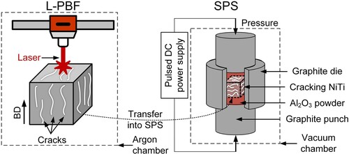
Crack healing was conducted in a spark plasma sintering furnace (FCT SPS system, type KCE-FCT HP D-25-SI, Germany). Each cracked sample was loaded into a graphite die with an inner diameter of 20 mm (ISO-68, Toyo Tanso, Japan), and its cracking direction (parallel to the L-PBF building) is perpendicular to the SPS loading direction ((b)). To support cracked samples, the gap between the graphite die and the sample was filled with Al2O3 powders. The SPS furnace was evacuated and flushed two times with Ar-gas of 5N purity (Linde, The Netherlands). The SPS healing process was conducted under the following procedures. First, the furnace was heated up to the target temperature in a range of 1223–1423 K with a heating rate of 20 K/min. The target pressure in a range of 13–22 MPa was applied with the duration in a range of 0.4–2 h. Finally, the pressure was released, and the sample was cooled naturally to room temperature.
Figure 2. Schematics for laser powder fusion and spark plasma sintering.
In order to achieve crack healing in L-PBF NiTi, various combinations of SPS pressure, temperature, and duration were optimised. It is crucial to prevent plastic deformation during the SPS healing process to preserve the [001] texture in NiTi. Therefore, the applied pressure during SPS should be lower than the yield strength of NiTi at the specific temperature. Since there is a lack of experimental data on NiTi yield strength above 673 K, an analytical fitting was performed based on reported values [Citation31]. Considering that the yield strength of NiTi decreases with increasing temperature and becomes zero above the melting point of NiTi (1583 K), a three-phase exponential decay function was used for the analytical fitting. The predicted curve is shown in , and predicted yield strength of NiTi fits well with reported values. The enlarged image in (b) reveals that the minimum predicted yield strength for all investigated temperatures is 37 MPa. The maximum SPS pressure of 22 MPa is selected to prevent significant plastic deformation after the SPS healing process. Detailed SPS parameters can be found in the Figure S1 of the Appendices. The SPS processing parameters and corresponding sample labels are shown in the .
Figure 1. Predicted temperature-dependent yield strength of NiTi versus the experimental results of NiTi yield stress [Citation31].
![Figure 1. Predicted temperature-dependent yield strength of NiTi versus the experimental results of NiTi yield stress [Citation31].](/cms/asset/75f6f6a4-6b4a-481f-b1e4-a92289a4a0d9/nvpp_a_2246437_f0001_oc.jpg)
Table 1. SPS processing parameters for healing NiTi cracks.
2.2. Characterisation
Before the metallographic examination, samples were ground, polished and tint etched and the detailed procedure can be found in our previous work [Citation12]. The etched microstructures were then examined via a Leica DMI 5000 optical microscope under the polarised light mode to show parent (austenitic) grains. Optical microscopy was performed using a Keyence VHX-6000 microscope enabled with a 2D stitching function to identify cracks in NiTi. Scanning electron microscopy (SEM) images and element analysis were captured by using a JEOL JSM 6500F (JEOL, Japan) equipped with an ultra-dry energy dispersive spectrometer (EDS) detector (Thermo Fisher Noran).
X-ray diffraction (XRD) analysis was conducted for phase identifications and phase fraction calculations in the as-fabricated and post-heat-treated samples. The measurements were conducted using the Bruker D8 Advance diffractometer in Cu-Kα radiation. The step size used was 0.03° 2θ with 45 kV and 40 mA current in a 2θ range of 17–90°.
Phase transformation behaviour was analysed by differential scanning calorimetry (DSC, Perkin Elmer DSC 8000) in a nitrogen atmosphere, with a cooling and heating rate of 10 K /min over a temperature range of 203–473 K. To avoid deformation and introduction of stresses, DSC samples with a dimension of ϕ 6 × 1 mm were prepared by electrical discharge machining (EDM) followed by subsequent sanding to remove EDM damages.
Transmission electron microscopy (TEM) images were taken by an FEI Talos F200X TEM FEI Talos F200X TEM equipment. TEM high-angle annular dark field (HAADF) observation, selected area electron diffraction (SAED), and energy dispersive spectroscopy (EDS) operations were also conducted. TEM foil samples were prepared by a focused Ga+ ion beam (FIB; FEI Helios 600i).
Relative density of materials was determined by the Archimedes method, using a theoretical maximum density of 6.45 g/cm3. The crack length density is estimated based on the ratio of crack length and measured area [Citation32], and the crack length was measured by using Image J to do statistical analysis for three optical microscopy images with ×200 magnification. Oxygen contents were measured by a Bruker oxygen–hydrogen analyser (G8 GALILEO).
2.3. Mechanical tests
Vickers hardness measurements were performed under the test force 1.0 kgf (further denoted as HV1) using an Automatic Microhardness Tester (Buehler Vickers). To evaluate the local mechanical properties of various NiTi samples, we conducted instrumented indentation tests at room temperature using a Zwick ZHU2.5 instrument. To avoid stress concentrations, a spherical ball indenter with a diameter of 0.5 mm was employed. Superelasticity was tested on an MTS 858 tabletop hydraulic test machine by applying uniaxial compression. A strain rate of 1.0 × 10⁻⁴ s−1 was applied and strains were measured by a contact-based high-temperature ceramic extensometer (632.53F-14, MTS). The temperature change was controlled by induction heating and air flow cooling. The temperature was measured by a K-type thermocouple welded onto the middle of NiTi sample surfaces. Prior to superelasticity tests, samples were heated to 473 K (above martensite starting temperatures, (b)) and then cooled to 353 K to ensure an austenitic state. All samples were loaded and unloaded along the L-PBF building direction.
3. Results
3.1. Microstructure, texture and phase transformation
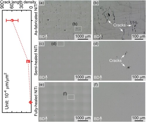
The cross-sectional images along the building direction (BD) are shown in . For the as-fabricated NiTi, cracks mainly propagate along the building direction ((a)) and penetrate multiple layers ((b)) and its average crack length density was found ∼5.9 × 10⁻³ μm−1. It can be seen that SPS can effectively heal cracks in L-PBF NiTi. By applying 22 MPa pressure under 1323 K with 1 h duration, cracks have been significantly eliminated and its crack length density decreases to ∼9.5 × 10⁻⁴ μm−1 (). To fully heal cracks, the pressure and heat holding time was prolonged to 2 h. As shown in (e,f), cracks were fully healed. This indicates the feasibility of the SPS for healing L-PBF NiTi cracks.
Figure 3. Crack length densities and optical microstructures: (a) and (b) as-fabricated NiTi; (c) and (d) Semi-healed NiTi; (e) and (f) Fully healed NiTi.
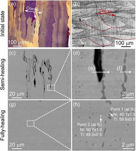
To further understand the crack healing mechanism, microstructures were further examined by tint OM, SEM and EDS. As shown in the polarised light OM image ((a)), intergranular cracks are dominant in the as-fabricated NiTi. By revealing melt pool boundaries, these intergranular cracks exist at melt pool centrelines. These hot cracks are resulting from solidification shrinkage at the final solidification zone when dendrites solidify in a columnar manner [Citation19]. The backscattered electron (BSE) images of semi-healed NiTi are shown in (c,d). The healed cracks (dark grey longitudinal part in (d)) show more Ti than the NiTi matrix ((f)), indicating that formed Ti-rich precipitates contribute to NiTi crack healing. The area around the unhealed crack ((e)) shows an even higher content of Ti than the Ti-rich precipitates ((f)). Therefore, it is possible to further deduce the crack healing mechanism by analysing microstructural features around unhealed and healed cracks. In the fully healed sample, there are two types of precipitate morphologies ((g,h)). The elongated precipitates along the building direction are responsible for crack healing and the dispersive particles originated from intragranular precipitation.
Figure 4. As-fabricated NiTi with cracks: optical microstructures showing (a) parent (austenite) phase at the polarised light and (b) melt pool features at the normal light. (c) BSE microstructures of the semi-healed NiTi and (d) its corresponding enlarged image; (e) and (d) EDS line scanning from (d). (g) and (h) BSE microstructures of fully healed NiTi and corresponding EDS mappings from (h). All images showing microstructures along the building direction.
XRD measurements were conducted at room temperature to identify phases. As shown in XRD patterns ((a)), all samples, including cracked L-PBF, semi-healed and fully healed NiTi, have B19′ as the main phase, and small peaks, corresponding to residual austenite (BCC_B2) and Ti2NiOx, are also present. To compare phase transformation temperature changes before and after the healing process, DSC measurements were carried on as fabricated and fully healed NiTi. After the SPS healing process, phase transformation temperatures were increased, and the corresponding temperatures are shown in . There is a ∼22 K increase of austenite finish temperature and a ∼8 J/g increase in the forward phase transformation enthalpy ((b) and ).
Figure 5. (a) XRD patterns of NiTi without and with different healing processes; (b) DSC curves of as-fabricated NiTi and fully-healed NiTi; TEM images of (c) as-fabricated NiTi (the bright field image) and (d) fully-healed NiTi (the angle annular dark field image); Inverse pole figures measured by XRD at 473 K, showing texture of the austenite phase: (e) as-fabricated NiTi and (f) fully-healed NiTi.
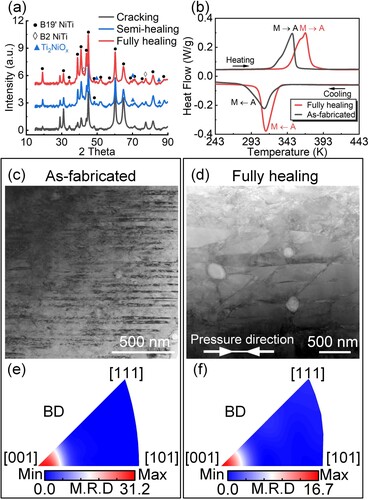
Table 2. Phase transformation temperatures determined by DSC tests.
The TEM images ((c,d)) also demonstrate that martensite is the main phase at room temperature for as-fabricated and fully healing samples, which is consistent with XRD and DSC results ((a,b)). The fully healed sample has wider martensite phases (∼269 nm) than that (∼32 nm) in the as-fabricated NiTi. Interestingly, the morphology of martensite in the fully healed NiTi has a tilted brick-like structure and the tilt direction is consistent with the SPS pressure direction ((d)). It is worth noting that, despite the high-temperature SPS, the strong [001] texture remains in the fully healed sample ((f)). Compared with the as-fabricated NiTi, there is a ∼ 50% decrease in the [001] texture intensity in the fully healed sample (((e,f)). The columnar grain morphology in the fully healed NiTi further indicates that the desirable [001] orientated grains for enhancing superelasticity are preserved (Figure S2).
Due to the resolution limitation of EDS equipped in the SEM, it is hard to analyse elements across grain boundaries of as-fabricated NiTi. Here, the STEM-EDS technique was applied to understand the elemental distribution along the crack flanks of the as-fabricated NiTi. As shown in the (a–e), more titanium and oxygen segregate at the grain boundary, indicating that hot cracking may result from these elemental segregations. The distance of elemental segregation is ∼14 nm.
Figure 6. (a) The STEM-HAADF image of as-fabricated NiTi and its corresponding EDS mappings, i.e. (b) Ti, (c) Ni and (d) O, and (e) a line scanning from (a); (f) and (g) TEM images of semi-healed NiTi and SAED pattern of Ti(O) from (g); (i) and (j) TEM images of fully-healed NiTi and SAED pattern of Ti2NiOx from (k).
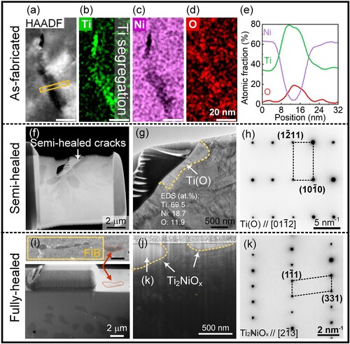
To reveal the cracking healing mechanism, the semi-healed (as an intermediate state) and the fully healed NiTi were further analysed by TEM. The FIB technique was applied to exact the TEM sample including the unhealed crack ((f)). There is an elongated precipitate along the flanks of the crack ((g)). Based on the selected area electron diffraction (SAED) ((h)) and EDS point analysis, the precipitate is determined as Ti containing oxygen (∼11.9 ± 1.4 at.%) (hereafter referred to as Ti(O)). Compared with the as-fabricated cracked NiTi, the width of Ti increases to ∼346 nm in the semi-healed NiTi. Therefore, the SPS process can promote the diffusion of Ti to the crack location.
To confirm precipitates along healed cracks in the fully healed sample, a TEM sample was prepared by FIB near the position of elongated precipitates. The interested area is shown in the (i) and the precipitate marked by the red arrows is used as a location reference. The SAED pattern ((k)) demonstrate that final precipitates along healed cracks in the fully healed sample are Ti2NiOx ((j)), which is also consistent with the XRD result ((a)).
3.2. Mechanical and functional properties of fully healed NiTi
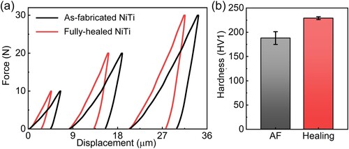
The purpose of this study is to heal cracks and preserve the superior superelasticity of [001] textured NiTi. To investigate the effect of the SPS treatment on mechanical properties of NiTi, instrumented indentation was conducted. Indentation displacement-force curves with varying maximum forces of 10, 20 and 30 N are shown in the (a). The fully healed NiTi always shows lower displacement values than the as-fabricated cracked NiTi under different force levels ((a)). This indicates an improved strength of NiTi after the SPS healing process. The fully healed sample also has a higher Vickers hardness (229 ± 3 HV1) than the as-fabricated cracked NiTi (188 ± 13 HV1) ((b)). The large deviation in hardness values of the as-fabricated cracked NiTi results from uniformly distributed cracks. Therefore, the SPS process not only contributes to the crack healing but also improves NiTi strength.
Figure 7. (a) Displacement-force curves and (b) Vickers hardness of as-fabricated cracked and fully healed NiTi.
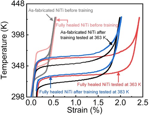
To verify whether the superelasticity still remain in the fully healed sample, thermomechanical tests were conducted. The as fabricated [001] NiTi shows an expected superelasticity ((a)), despite the existence of cracks. This is due to that the loading or unloading direction is parallel to the crack propagation direction, which makes strain or stress continuously transfer within samples. Hence, the [001] orientation still can play an effective role on enhancing superelasticity. With thermomechanical cycles under a constant nominal deformation of 4% strain, the superelastic strain value almost remains constant as ∼3.2% and residual strain accumulate to 0.5% after 50 cycles. The accumulation of residual strain results from phase transformation induced plasticity and can reach a saturated state after cycles.
Figure 8. Cyclic thermomechanical tests: (a) as fabricated and (b) fully healed NiTi under 363 K loading and unloading, and (c) fully healed NiTi under 383 K loading and unloading. (d) Superelastic strains as a function of thermomechanical cycle of all tested samples.
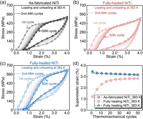
Under the same loading and unloading temperature of 363 K, the fully healed sample also shows superelastic behaviour ((b)). At the first thermomechanical cycle, the recoverable strain is only ∼1.3%. Surprisingly, its superelasticity is enhanced with the number of cycles and the superelastic strain increases to 2.9% after 50 thermomechanical cycles (∼223% increase of superelastic strain compared with the first cycle). Compared with the literature [Citation33], superelasticity usually degrades with thermomechanical cycling. To best of authors’ knowledge. It is, for the first time, found in additively manufactured NiTi that superelasticity is enhanced by thermomechanical cycling.
4. Discussion
4.1. Cracking and healing mechanism
4.1.1. Crack formation
Before discussing the crack healing mechanism, it is important to understand the crack formation mechanism. NiTi cracks are intergranular ((a)), which is a typical feature of solidification cracking (or hot cracking) [Citation34]. The solidification behaviour of Ni (49.6 at. %)-Ti is calculated based on the Scheil-Gulliver model ((a)). Since this model assumes that no diffusion occurs in solid phases and infinitely fast diffusion occurs in the liquid, it is suitable for L-PBF solidification with a high cooling rate. At the final stage of solidification (the solid fraction is higher than 0.9), the solidification temperature range is ∼237 K ((a)). As reported by Kou [Citation35], the solidification cracking susceptibility can be evaluated by the steepness of the curve of T vs (fS)1/2 when (fS)1/2 is close to 1, where T is the temperature and fS is the solid fraction. For Ni(49.6 at.%)-Ti, the steepness of is ∼7431 K, which is ∼1.8 times higher than the high cracking susceptibility of 7075 Al alloy [Citation36]. The high cracking susceptibility of NiTi indicates that cracking along grain boundaries is prone to occur due to stresses introduced by solidification shrinkage and thermal contraction.
Figure 10. (a) The solidification path of Ni (49.6 at. %)-Ti based on the Scheil-Gulliver model. (b) the content of Ni and Ti in the liquid as a function of temperature.
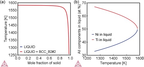
Due to the solute redistribution during the Ni (49.6 at. %)-Ti alloy, Ti enriches the residual liquid ((b)). In the solidification microstructure, dendrites grow and merge forming grains, and at the grain boundaries liquid films may remain. Therefore, Ti segregation can be observed along the grain boundaries ((a–e)).
4.1.2. Crack healing
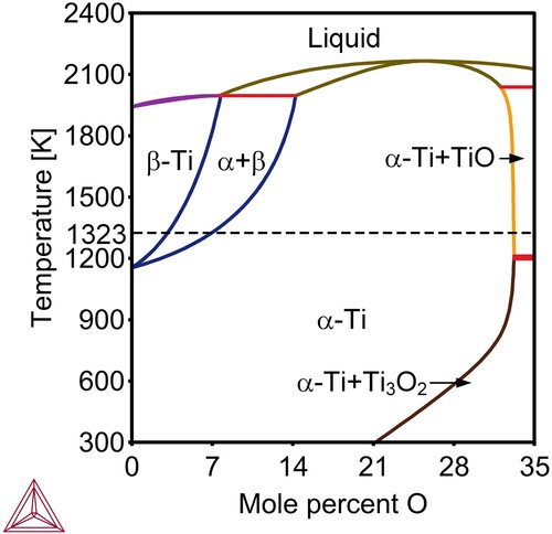
As shown in the and , the healing of cracks is achieved by the participation of diffusion bonding. The 1323 K-1 h-22 MPa SPS healing process results in the formation of Ti(O). Despite the L-PBF and SPS processes are under Ar (purity of 99.999%) protection, oxygen is inevitable and can be found in NiTi [Citation30]. As Ti is an reactive element, Ti is easy to react with oxygen at high temperate [Citation37]. The Ti-O binary phase diagram () shows that Ti has a large solubility of oxygen, and its solubility of oxygen can reach to ∼32 at. % at 1323 K (the SPS processing temperature). The EDS result at the semi-healed NiTi shows that ∼11.9 at. % oxygen is present within Ti ((g)), which is lower than the maximum solubility of oxygen in Ti. Therefore, Ti(O) exists in the semi-healed cracking interface.
Figure 11. The binary phase diagram of Ti-O.
For the entire system, the Ti(O) does not exist in a state of thermodynamic equilibrium. With increasing holding duration to 2 h under 1323 K and 22 MPa, the Ti2NiOx phase forms by consuming Ti(O) and the chemical bonding is created, which closes cracks. In the Ni-Ti system, the diffusion rate of Ti into Ni is much higher than that of Ni into Ti [Citation38]. At 1223 K, close to our SPS processing temperature of 1323 K, the diffusion rate of Ti is 2.0 × 10⁻¹⁰ cm−2 in NiTi, which is two orders of magnitude higher than that of Ni (1.5 × 10⁻¹² cm−2) in NiTi. Meanwhile, there is a concentration gradient of Ti between Ti(O) and NiTi matrix. Therefore, increasing the duration of the SPS process promotes Ti atoms to diffuse from Ti(O) into NiTi. Based on the Ni-Ti phase diagram [Citation1], NiTi has a limited solubility of Ti and the increase of Ti in NiTi results in the formation a Ti2Ni phase. Furthermore, oxygen can stabilise Ti2Ni phase [Citation39], and Ti2NiOx is finally present to act as the crack bonding phase ((g,h) and (i–k)). The formation of Ti2Ni phase has been also observed in the interface of Ti and NiTi of Ni-Ti diffusion couples [Citation38].
Based on the above discussion, the chemical reaction of the whole healing process can be summarised as follows:
(1)
(1)
(2)
(2) As external oxygen participates in the healing process, these reactions will result in volume expansion. The increased oxygen levels in the fully healed NiTi (940 ppm), compared with the as-fabricated cracked NiTi, (447 ppm) has been confirmed by oxygen measurement (Figure S3(b) and (c)). Additionally, in the fully healed NiTi, crack flanks can be further closed by the applied pressure. Therefore, the crack healing is attributed to the synergistic effect from the following sequential three aspects: (1) Crack flanks are closed by external pressure provided by SPS; (2) the remaining gaps at the flanks are filled by Ti2NOx due to the volume expansion reaction; (3) Chemical bonding is created by diffusion and remains effective after releasing pressure. It should be mentioned that oxygen is usually considered as a undesirable contamination for L-PBF NiTi, as it deteriorates a printability of NiTi [Citation30,Citation40]. In this study, we utilise the oxygen to heal cracks in NiTi. The ability of Ti2NiOx in crack healing is further demonstrated by EBSD in a larger scale (compared with TEM results shown in the ) (Figure. S4).
4.2. Phase transformation temperatures and superelastic behaviour
DSC results show that the SPS healing process increases NiTi phase transformation temperatures ( and ). For the forward transformation, the main difference between as-fabricated cracked and fully healed NiTi is shown in the martensite finish temperature (Mf). The Mf in the fully healed NiTi is 21 K higher than that in the as-fabricated cracked NiTi. A higher Mf suggests that a decreased driving force is necessary to facilitate the transformation [Citation41]. It has been reported that crystal defects, such as dislocations [Citation42], point defects [Citation43] and grain boundaries [Citation44], can impede martensite transformation and result in the decrease of phase transformation temperatures. In this study, the fully healed NiTi underwent a high-temperature treatment (1323 K), higher than the NiTi recrystallization temperature [Citation45], which can eliminate crystal defects [Citation46]. Therefore, an increased martensitic transformation temperature is found in the fully healed NiTi. In addition, the SPS healing process promotes the formation of Ti2NiOx by decreasing the Ni content in NiTi matrix, which further increase phase transformation temperatures [Citation39].
Due to the increased phase transformation temperatures, the fully healed NiTi shows distinct superelastic behaviour from the as-fabricated cracked NiTi ((a,b)) at the same loading temperature of 363 K. As the loading temperature of 363 K is lower than the Af = 368 K of fully healed NiTi, there is a lack of sufficient driving force to trigger the reserve transformation from stress-induced martensite to austenite [Citation47]. Therefore, a small superelastic strain of ∼1.2% ((c)) is present after the first thermomechanical cycle. When increasing the test temperature to 383 K (above Af of fully healed NiTi), desirable superelastic ability, comparable with the as-fabricated NiTi, is shown in the fully healed NiTi ((c,d)).
It should be noted that, the superelasticity of fully healed NiTi shows an unusual enhancement with thermomechanical cycles, which is different from the commonly seen superelastic degradation [Citation33,Citation48,Citation49]. For cyclic thermomechanical NiTi, there are two generally accepted viewpoints: (1) the functional degradation of NiTi is due to dislocation accumulation and plastic deformation accompanying martensite transformation [Citation33,Citation48,Citation49]; (2) oriented internal stresses, induced by thermomechanical cycles, can promote phase transformation and narrow the stress hysteresis [Citation50–52]. Therefore, it can be concluded that the enhanced superelasticity in the fully healed NiTi tested at 363 K is due to the dominance of internal stress assisted phase transformation. In other words, the orientated internal stress induced by thermomechanical cycles is more effective to evoke the reverse transformation during unloading. It provides an additional driving force to promote superelastic strain, even when there is irrecoverable plastic strain caused by dislocation accumulation.
The level of internal stress within samples can be estimated by two-way shape memory behaviour. After thermomechanical cycles, samples show decreased phase transformation temperatures (). This is because internal stresses induced by thermomechanical cycles decrease the required thermal driving force of phase transformations. As the superelastic behaviour obeys the Clausius–Clapeyron relationship [Citation1,Citation53], the internal stress can be quantitatively related to the Ms shift, i.e.:
(3)
(3) where
is the internal stress (MPa),
(K) is the martensite start temperature shift,
(J/g) is the enthalpy of transformation (measured by DSC shown in the ),
= 6.45 g/cm3 is the NiTi density [Citation54],
= 0.08 (-) is a transformation strain [Citation53] and T0, herein using the equilibrium temperature of the reserve transformation (
), is 330 K for as-fabricated cracked NiTi and 340 K for the fully healed NiTi (). Based on strain-temperature curves of samples before and after thermal mechanical tests () and considering the Ms shift, the as-fabricated cracked NiTi has a ∼7 K shift, and the fully healed NiTi has 17 and 13 K shifts for tests under 363 and 383 K, respectively. By calculating the Equation (3), the internal stress for the as-fabricated cracked and the fully healed NiTi tests under 363 and 383 K, are 41, 129 and 98 MPa. Such estimation also fits well with the two-way shape memory behaviour (). The fully healed NiTi tested at 363 K has the largest two-way shape memory strain, indicating a highest internal stress.
Figure 9. Two-way shape memory effect response of as fabricated and fully healed NiTi before and after thermomechanical training.
It is worthy to note that the as-fabricated cracked NiTi after 363 K thermomechanical cycles (the dark black line in the ) and the fully healed NiTi after 383 K thermomechanical cycles (the blue line in the ) have similar two-way shape memory strains (), despite ∼ 2 times higher estimated internal stress in the fully healed NiTi. This is not contradictory, as based on the Clausius–Clapeyron relationship (Equationequation 3(3)
(3) ), critical stresses for martensitic phase transformation increase with temperature. The fully healed NiTi after training tested at 383 K (the blue line in the ) has a ∼6 K higher Ms than the as-fabricated cracked NiTi after training tested at 363 K (the dark black line in the ). This increased phase transformation results in a ∼46 MPa increase of critical stress for martensitic transformation. After excluding the temperature effect on phase transformation stresses, the fully healed NiTi after training tested at 383 K has an equivalent 52 MPa internal stress, which is comparable with the internal stress of 41 MPa in the as-fabricated crack NiTi.
Therefore, the gradually enhanced superelastic ability with thermomechanical cycles and the large two-way shape memory strain (∼2.4%) in fully healed NiTi is attributed to a higher internal stress level. It should be highlighted that such two-way shape memory strain is superior, as it is comparable with the heat-treated cold-drawn NiTi even at a higher deformation level (∼8.5% training deformation [Citation55] and a 8% pre-strain [Citation53]). The reason higher internal stress can be induced into full healed NiTi may result from the presence of intergranular Ti2Ni precipitates. In our previous work, we have demonstrated that intergranular Ti2Ni precipitates contributes to enclosing internal stress by strain partitioning. The effect of Ti2Ni on the two-way effect in the fully healed NiTi will be investigated in our follow-up works.
5. Conclusions
In this study, we investigated the crack-healing of [001]-textured L-PBF NiTi using SPS (Spark Plasma Sintering). Under optimised processing conditions, SPS can successfully eliminate cracks induced by the L-PBF process. We systematically examined the mechanism of crack-healing, as well as the resulting mechanical and functional properties. The main conclusions can be summarised as follows:
Spark plasma sintering is demonstrated as an effective method for healing hot cracks in [001]-textured L-PBF NiTi. Cracks are healed through diffusion bonding, and the flanks in the cracks are filled with in-situ formed Ti2NiOx precipitates.
This work utilised oxygen, which is traditionally considered detrimental to L-PBF parts, in the healing process. The oxygen engages in the following reactions:
.
The SPS healing process improves the mechanical properties of NiTi by eliminating cracks and increases the stable superelastic temperature by 20 K compared to the as-fabricated L-PBF cracked NiTi.
An unusual enhancement in superelasticity is observed in the SPS-healed NiTi with thermomechanical cycles. This phenomenon can be attributed to the dominant effect of internal stress on reducing the critical stress required for phase transformation.
The SPS-healed NiTi shows a pronounced two-way shape memory response, resulting in approximately 2.4% two-way shape memory strain under a maximum training strain of 4%. This effect is due to a high internal stress level in the SPS-healed NiTi.
Our findings indicate that SPS is an alternative technique for healing hot cracks in L-PBF NiTi and can improve NiTi's mechanical properties and superelasticity. The revealed crack-healing mechanism also provides novel insights for designing crack-healing strategies in other alloy systems. In this study, we focused on investigating cubic NiTi samples to demonstrate the feasibility of SPS for healing cracks in L-PBF NiTi. Given the capability of AM in fabricating complex structured components, more work on healing architectured NiTi parts will be carried out in our future work.
Acknowledgements
Jia-Ning Zhu thanks the China Scholarship Council (CSC) for its financial support. The authors would like to thank Dr. Richard Huizenga at the Department of Materials Science and Engineering of the Delft University of Technology for the X-ray analysis and Ing. The authors are also grateful to Dr. Ir. F.D. Tichelaar, Kavli Institute of Nanoscience, Delft University of Technology for the support with TEM imaging. We also thank Mr. Tim Boot for helping us with oxygen content measurement.
Disclosure statement
No potential conflict of interest was reported by the author(s).
Additional information
Funding
References
- Otsuka K, Ren X. Physical metallurgy of Ti–Ni-based shape memory alloys. Prog Mater Sci. 2005;50(5):511–678. doi:10.1016/j.pmatsci.2004.10.001
- Mohd Jani J, Leary M, Subic A, et al. A review of shape memory alloy research, applications and opportunities. Mater Des. 2014;56:1078–1113. doi:10.1016/j.matdes.2013.11.084.
- Dye D. Towards practical actuators. Nat Mater. 2015;14(8):760–761. doi:10.1038/nmat4362
- Ren X, Otsuka K. Origin of rubber-like behaviour in metal alloys. Nature. 1997;389(6651):579–582. doi:10.1038/39277
- Elahinia M, Shayesteh Moghaddam N, Taheri Andani M, et al. Fabrication of NiTi through additive manufacturing: a review. Prog Mater Sci. 2016;83:630–663. doi:10.1016/j.pmatsci.2016.08.001
- Nakahata T. 4 – Industrial processing of titanium–nickel (Ti–Ni) shape memory alloys (SMAs) to achieve key properties. In: Yamauchi K, Ohkata I, Tsuchiya K, Miyazaki S, editors. Shape memory and superelastic alloys. Sawston (UK): Woodhead Publishing; 2011. p. 53–62.
- Elahinia MH, Hashemi M, Tabesh M, et al. Manufacturing and processing of NiTi implants: a review. Prog Mater Sci. 2012;57(5):911–946. doi:10.1016/j.pmatsci.2011.11.001
- Laplanche G, Kazuch A, Eggeler G. Processing of NiTi shape memory sheets – microstructural heterogeneity and evolution of texture. J Alloys Compd. 2015;651:333–339. doi:10.1016/j.jallcom.2015.08.127
- Khoo ZX, Teoh JEM, Liu Y, et al. 3D printing of smart materials: a review on recent progresses in 4D printing. Virtual Phys Prototyp. 2015;10(3):103–122. doi:10.1080/17452759.2015.1097054
- Sing SL, Yeong WY. Laser powder bed fusion for metal additive manufacturing: perspectives on recent developments. Virtual Phys Prototyp. 2020;15(3):359–370. doi:10.1080/17452759.2020.1779999
- Yan Z, Zhu J-N, Borisov E, et al. Superelastic response and damping behavior of additively manufactured Nitinol architectured materials. Addit Manuf. 2023;68:103505. doi:10.1016/j.addma.2023.103505
- Zhu J-N, Borisov E, Liang X, et al. Controlling microstructure evolution and phase transformation behavior in additive manufacturing of nitinol shape memory alloys by tuning hatch distance. J Mater Sci. 2022;57(10):6066–6084. doi:10.1007/s10853-022-07007-z
- Zhu J-N, Liu K, Riemslag T, et al. Achieving superelasticity in additively manufactured Ni-lean NiTi by crystallographic design. Mater Des. 2023;230:111949. doi:10.1016/j.matdes.2023.111949
- Gäumann M, Bezençon C, Canalis P, et al. Single-crystal laser deposition of superalloys: processing–microstructure maps. Acta Mater. 2001;49(6):1051–1062. doi:10.1016/S1359-6454(00)00367-0
- Gall K, Lim TJ, McDowell DL, et al. The role of intergranular constraint on the stress-induced martensitic transformation in textured polycrystalline NiTi. Int J Plast. 2000;16(10):1189–1214. doi:10.1016/S0749-6419(00)00007-3
- Sehitoglu H, Karaman I, Anderson R, et al. Compressive response of NiTi single crystals. Acta Mater. 2000;48(13):3311–3326. doi:10.1016/S1359-6454(00)00153-1
- Capper P. Bulk Bridgman growth of cadmium mercury telluride for IR applications. J Mater Sci: Mater Electron. 2001;12(8):423–428. doi:10.1023/A:1011883213530
- Köhnen P, Létang M, Voshage M, et al. Understanding the process-microstructure correlations for tailoring the mechanical properties of L-PBF produced austenitic advanced high strength steel. Addit Manuf. 2019;30:100914. doi:10.1016/j.addma.2019.100914
- Martin JH, Yahata BD, Hundley JM, et al. 3D printing of high-strength aluminium alloys. Nature. 2017;549(7672):365–369. doi:10.1038/nature23894
- Rometsch PA, Zhu Y, Wu X, et al. Review of high-strength aluminium alloys for additive manufacturing by laser powder bed fusion. Mater Des. 2022;219:110779. doi:10.1016/j.matdes.2022.110779.
- Cao Y, Zhou X, Cong D, et al. Large tunable elastocaloric effect in additively manufactured Ni–Ti shape memory alloys. Acta Mater. 2020;194:178–189. doi:10.1016/j.actamat.2020.04.007
- Karami K, Blok A, Weber L, et al. Continuous and pulsed selective laser melting of Ti6Al4V lattice structures: effect of post-processing on microstructural anisotropy and fatigue behaviour. Addit Manuf. 2020;36:101433. doi:10.1016/j.addma.2020.101433
- Yang L, Yan C, Cao W, et al. Compression–compression fatigue behaviour of gyroid-type triply periodic minimal surface porous structures fabricated by selective laser melting. Acta Mater. 2019;181:49–66. doi:10.1016/j.actamat.2019.09.042
- Wang H, Chen L, Dovgyy B, et al. Micro-cracking, microstructure and mechanical properties of Hastelloy-X alloy printed by laser powder bed fusion: as-built, annealed and hot-isostatic pressed. Addit Manuf. 2021;39:101853. doi:10.1016/j.addma.2021.101853
- Gheysen J, Tingaud D, Villanova J, et al. Exceptional fatigue life and ductility of new liquid healing hot isostatic pressing especially tailored for additive manufactured aluminum alloys. Scr Mater. 2023;233:115512. doi:10.1016/j.scriptamat.2023.115512
- Huang J, Guo L, Zhong L. Synergistic healing mechanism of self-healing ceramics coating. Ceram Int. 2022;48(5):6520–6527. doi:10.1016/j.ceramint.2021.11.198
- Popovich VA, Borisov EV, Popovich AA, et al. Impact of heat treatment on mechanical behaviour of Inconel 718 processed with tailored microstructure by selective laser melting. Mater Des. 2017;131:12–22. doi:10.1016/j.matdes.2017.05.065
- Stevens RA, Flewitt PEJ. Hot isostatic pressing to remove porosity & creep damage. Mater Des. 1982;3(3):461–469. doi:10.1016/0261-3069(82)90112-1
- Vilanova M, Garciandia F, Sainz S, et al. The limit of hot isostatic pressing for healing cracks present in an additively manufactured nickel superalloy. J Mater Process Technol. 2022;300:117398. doi:10.1016/j.jmatprotec.2021.117398
- Hu Z-Y, Zhang Z-H, Cheng X-W, et al. A review of multi-physical fields induced phenomena and effects in spark plasma sintering: fundamentals and applications. Mater Des. 2020;191:108662. doi:10.1016/j.matdes.2020.108662
- Adharapurapu RR, Jiang F, Vecchio KS, et al. Response of NiTi shape memory alloy at high strain rate: a systematic investigation of temperature effects on tension–compression asymmetry. Acta Mater. 2006;54(17):4609–4620. doi:10.1016/j.actamat.2006.05.047
- Zhou Z, Lei Q, Yan Z, et al. Effects of process parameters on microstructure and cracking susceptibility of a single crystal superalloy fabricated by directed energy deposition. Mater Des. 2021;198:109296. doi:10.1016/j.matdes.2020.109296
- Hsu W-N, Polatidis E, Šmíd M, et al. Deformation and degradation of superelastic NiTi under multiaxial loading. Acta Mater. 2019;167:149–158. doi:10.1016/j.actamat.2019.01.047
- Kou S. Solidification and liquation cracking issues in welding. JOM. 2003;55(6):37–42. doi:10.1007/s11837-003-0137-4
- Kou S. A criterion for cracking during solidification. Acta Mater. 2015;88:366–374. doi:10.1016/j.actamat.2015.01.034
- Kou S. A simple index for predicting the susceptibility to solidification cracking. Weld J. 2015b;94(12):374–388.
- Inoue Y, Hiraide N, Hayashi A, et al. Effect of titanium on oxidation behavior of high-purity ferritic stainless steel. Mater Trans. 2019;60(9):1968–1976. doi:10.2320/matertrans.MT-M2019123
- Hu L, Xue Y, Shi F. Intermetallic formation and mechanical properties of Ni-Ti diffusion couples. Mater Des. 2017;130:175–182. doi:10.1016/j.matdes.2017.05.055
- Frenzel J, George EP, Dlouhy A, et al. Influence of Ni on martensitic phase transformations in NiTi shape memory alloys. Acta Mater. 2010;58(9):3444–3458. doi:10.1016/j.actamat.2010.02.019
- Wang X, Yu J, Liu J, et al. Effect of process parameters on the phase transformation behavior and tensile properties of NiTi shape memory alloys fabricated by selective laser melting. Addit Manuf. 2020;36:101545. doi:10.1016/j.addma.2020.101545
- Hamilton RF, Palmer TA, Bimber BA. Spatial characterization of the thermal-induced phase transformation throughout as-deposited additive manufactured NiTi bulk builds. Scr Mater. 2015;101:56–59. doi:10.1016/j.scriptamat.2015.01.018
- Simon T, Kröger A, Somsen C, et al. On the multiplication of dislocations during martensitic transformations in NiTi shape memory alloys. Acta Mater. 2010;58(5):1850–1860. doi:10.1016/j.actamat.2009.11.028
- Mansouri Tehrani A, Shahrokhshahi H, Parvin N, et al. Influencing the martensitic phase transformation in NiTi through point defects. J Appl Phys. 2015;118(1). doi:10.1063/1.4923474
- Ko W-S, Maisel SB, Grabowski B, et al. Atomic scale processes of phase transformations in nanocrystalline NiTi shape-memory alloys. Acta Mater. 2017;123:90–101. doi:10.1016/j.actamat.2016.10.019
- Tadayyon G, Mazinani M, Guo Y, et al. The effect of annealing on the mechanical properties and microstructural evolution of Ti-rich NiTi shape memory alloy. Mater Sci Eng A. 2016;662:564–577. doi:10.1016/j.msea.2016.03.004
- Alaneme KK, Okotete EA. Recrystallization mechanisms and microstructure development in emerging metallic materials: a review. J Sci Adv Mater Dev. 2019;4(1):19–33. doi:10.1016/j.jsamd.2018.12.007
- Huang X, Liu Y. Effect of annealing on the transformation behavior and superelasticity of NiTi shape memory alloy. Scr Mater. 2001;45(2):153–160. doi:10.1016/S1359-6462(01)01005-3
- Song D, Yu C, Zhang C, et al. Superelasticity degradation of NiTi shape memory alloy in wide ranges of temperature and loading level: experimental observation and micromechanical constitutive model. Int J Plast. 2023;161:103487. doi:10.1016/j.ijplas.2022.103487
- Tyc O, Heller L, Šittner P. Lattice defects generated by cyclic thermomechanical loading of superelastic NiTi wire. Shape Mem Superelasticity. 2021;7(1):65–88. doi:10.1007/s40830-021-00315-4
- Wada K, Liu Y. Thermomechanical training and the shape recovery characteristics of NiTi alloys. Mater Sci Eng A. 2008;481-482:166–169. doi:10.1016/j.msea.2007.02.143
- Ponikarova I, Belyaev S, Resnina N. Degradation of two-way shape memory effect due to the relaxation of internal oriented stress in NiTi alloy on holding at 640÷700 K. Mech Mater. 2019;138:103174. doi:10.1016/j.mechmat.2019.103174
- Wang X, Xu B, Yue Z. Phase transformation behavior of pseudoelastic NiTi shape memory alloys under large strain. J Alloys Compd. 2008;463(1):417–422. doi:10.1016/j.jallcom.2007.09.029
- Eucken S, Duerig TW. The effects of pseudoelastic prestraining on the tensile behaviour and two-way shape memory effect in aged NiTi. Acta Metall. 1989;37(8):2245–2252. doi:10.1016/0001-6160(89)90151-X
- Zhu J-N, Borisov E, Liang X, et al. Predictive analytical modelling and experimental validation of processing maps in additive manufacturing of nitinol alloys. Addit Manuf. 2021;38:101802. doi:10.1016/j.addma.2020.101802
- Scherngell H, Kneissl AC. Training and stability of the intrinsic two-way shape memory effect in Ni-Ti alloys. Scr Mater. 1998;39(2):205–212. doi:10.1016/S1359-6462(98)00155-9
Appendices
Figure S1. Optical microstructure of NiTi processed by various SPS parameters (shown in the figure in the format of ‘Temperature (K)-Holding time (h)-Pressure (MPa)’). All images are with 200 μm scale bars. Micro-cracks are marked by black arrows in the figure.
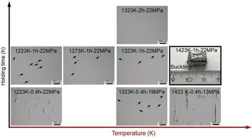
Figure S2. Optical microstructure images taken under the polarised light condition showing parent phase grain morphologies before and after the SPS healing process. The columnar grains parallel to the L-PBF building direction are still preserved after the healing process. This is consistent with the high-temperature texture measurement ( (f)).
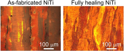
Figure S3. (a) Measured relative density of as-fabricated cracked and fully healed NiTi samples. There is an increased relative density after SPS healing process, indicating the elimination of crack flanks. (b) and (c) Measured oxygen contents in as-fabricated cracked and fully healed NiTi samples by using a Bruker oxygen-hydrogen analyser (G8 GALILEO). Dash lines are repeated curves. After the SPS process, an increased oxygen content can be seen.
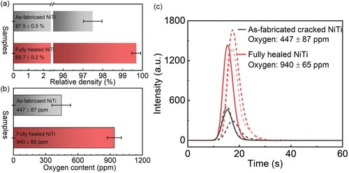
Figure S4. (a) A EBSD map with the Ti2NiOx phase inverse pole figure colour map overlaid on an image quality map (showing the morphology of B19′ martensite variants) in the fully healed NiTi. (b) A Kikuchi pattern obtained from the Ti2NOx phase. CS: cross-section. This EBSD result further demonstrates the formation of Ti2NiOx and its role in the healing of NiTi cracks.