
 ?Mathematical formulae have been encoded as MathML and are displayed in this HTML version using MathJax in order to improve their display. Uncheck the box to turn MathJax off. This feature requires Javascript. Click on a formula to zoom.
ABSTRACT
3D inkjet (3D-IJ) printing is recognised for its potential in high-value applications, including printed electronics, tissue engineering and bio-inspired structures, given its precision and ability to deposit multiple materials. The quality of 3D-IJ printed parts is contingent upon meticulous control of the process governing parameters. This study experimentally investigates the influence of various parameters within the 3D-IJ process, i.e., printing resolution, coverage percentage, droplet volume, printing speed and UV-Power and their interaction effects on the printed layer height. The results were analysed statistically using ANOVA and a quadratic regression model was developed to quantitatively identify the relationship between the process response and parameters. Except UV-Power, all parameters, and their interactions with each other had noticeable effects on the printed layer height, with a distinct trend observed for each, affecting the height that ranged from 4.73 µm to 98.58 µm. Increasing printing resolution, coverage percentage and droplet volume resulted in an increase in layer height as all three parameters contribute to a larger volume of dispensed material per layer. Printing resolution was found to be the most influential parameter, evidenced by a significant p-value. Finally, the optimal printing parameters for two scenarios, highest printed layer and cost-effective printing were individually identified.
1. Introduction
3D inkjet printing (3D-IJ) is an additive manufacturing technology (AM) which produces specimens in a layer-by-layer manner by deploying piezoelectric inkjet technology and predominantly UV-curable inks. 3D inkjet printing is also known as material jetting, a term defined in the latest standard on additive manufacturing ASTM52900 [Citation1]. The ASTM52900 standard classifies existing 3D printing technologies into seven major types: binder jetting, directed energy deposition, material extrusion, material jetting, powder bed fusion, sheet lamination and vat photopolymerisation. The large variety of 3D printing technologies paired with the great number of processable materials, ranging from plastic [Citation2] to metals [Citation3] to composite [Citation4] and ceramic materials [Citation5], allows the fabrication of innovative parts.
3D inkjet printing generates a single layer based on mainly two steps – (1) printing and (2) curing – which will be repeated multiple times until the desired geometry/height is completed. 3D-IJ is able to generate complex multi-material geometries with few microns of dimensional resolution. Building up intricate complex structures such as printed electronics [Citation6–8], scaffolds for tissue engineering [Citation9–11], microfluidic devices [Citation12,Citation13] or photorealistic biomimicking multi-coloured parts [Citation14,Citation15] are among the several potential applications 3D-IJ can be used for. 3D-IJ possesses a complex dynamic process in which droplet firing at high frequency, droplets/substrate interaction, droplet coalescence and curing process take place while the print station is in motion [Citation16]. A recent comprehensive review on 3D inkjet printing revealed that this technology is still facing multiple challenges in order to be fully adopted for advanced applications [Citation17]. 3D-IJ has been the focus of growing attention among research groups and various fields of industry due to its capability to enable high-throughput and high-resolution printing for various applications, such as microlenses [Citation18], printing of reactive [Citation19] and electromagnetic responsive inks [Citation20] and solid oxide fuel cells [Citation21]. Due to the promising capabilities of both piezo-based and EHD (electrohydrodynamic) inkjet printing to fabricate printed electronics, a surge of interest in the field of printed electronics [Citation22–24] and numerous optimisation strategies [Citation25–28] and experimental-based studies [Citation29,Citation30] of process parameters have been reported. This study will be focusing on the process parameters in piezo-based inkjet printing (3D inkjet printing) which differs from those relevant for EHD printing due to their different approach of generating droplet.
In general, the 3D inkjet printing process is highly dependent on the dynamic, physical and mechanical behaviour of the involved elements in addition to the chemical responses of the dispensed ink during the curing process. In particular, the process outcome is significantly influenced by the inherent ink properties (viscosity, surface tension [Citation31,Citation32] and shrinkage behaviour upon curing [Citation33,Citation34]), the printing environment [Citation35,Citation36] and the droplet/substrate-interaction which includes the factors contact angle, droplet size/volume, substrate roughness [Citation37–39] and droplet impact velocity [Citation40]. The latter one defines for instance the threshold of when splashing occurs. Further influencing factors of the printing process are the printhead parameters (waveform and firing frequency [Citation41–43]), printing distance [Citation44], the printing and curing parameters (printing speed, distance between substrate and printhead [Citation45,Citation46], printing resolution [Citation37,Citation47,Citation48], curing parameters [Citation49,Citation50], curing strategy [Citation51] and coverage percentage [Citation52,Citation53]). Coverage percentage describes how many of the pixels in the print file representing a printed dot are actually printed.
A stable droplet generation with barely any satellite droplets is crucial in order to achieve high-quality prints, apart from a proper curing process of the ink. Satellite droplets are small droplets emerging from the breakup of the tail of the primary droplet [Citation54]. In some cases, these small droplets manage to catch up and merge with the primary droplets in the course of the travelling before impacting the substrate and thus have no detrimental effect on the print result [Citation55]. In other cases, satellite droplets result in a misting of the printed pattern [Citation54,Citation56,Citation57]. The drop formation can be assessed in-flight by means of a drop watcher, with a flash rate tuned to the frequency of droplet ejection.
After depositing the ink, either UV- [Citation58] and/or thermal curing [Citation59] is required in order to solidify the printed layer. Thermal curing is mostly applied for solvent-based ink to evaporate the solvent carrier in order to achieve a solid layer and in order to generate the functionality, such as conductivity [Citation60]. UV-curable inks, by contrast, react upon UV-light which initiates a chemical reaction inside the ink, causing the monomers to cross-link and to solidify. The curing of photosensitive inks by UV-radiation has been widely investigated in terms of its kinetic behaviour and the process response, considering parameters such as UV-light intensity, exposure time, oxygen inhibition, temperature, etc. [Citation36,Citation61,Citation62]. Lin et al. concluded from their model on cure kinetics, that the cure depth is positively correlated to the photoinitiator concentration and light dose, but inversely correlated to the oxygen concentration and the viscosity [Citation61]. Pilkenton et al. observed that the presence of oxygen restricts the degree of conversion and lowers the mechanical properties which could be substantially improved by not only curing in an inert environment, but also by purging the sample with an inert gas prior to curing [Citation36]. Zhao et al. established a model for predicting the degree of conversion of a cured specimen considering UV-intensity, curing strategy and layer attenuation. The model has been applied and validated for three different curing strategies with which different responses were reported [Citation51].
During the curing process, the material is inherently subject to a certain degree of shrinkage as well, as the material becomes denser either due to the evaporation of the carrier in the case of a solvent-based ink, or by the crosslinking process of a UV-curable material. Elkaseer et al. implemented a height correcting factor in a proposed simulation model to consider the shrinkage of the predicted layer height after curing [Citation52]. Negro et al. printed bioinks and these trials resulted in a dimensional decrease of 5% of the printed specimen in x- and y-direction which span the plane of the printed layer, while the height in z-direction was 10% greater than the expected theoretical values [Citation63].
Furthermore, it was observed that the contact angle between the ink and the substrate also had an effect on the shape of the droplet and eventually the achievable geometry and final layer height. Stringer and Derby developed a model based on the findings of Duineveld [Citation37] to predict the stability of inkjet-printed lines on a substrate. The bead width of a stable printed line can be calculated from the droplet diameter during flight which is directly related to the droplet volume, the droplet spacing and wetting condition between the substrate and the liquid droplet [Citation47]. Once the maximum centre-to-centre distance of two adjacent droplets is exceeded, an undesired bulging of the printed lines occurs. The validation of this model has been conducted for drop volumes in the range of 50–100 pl at 1 kHz [Citation47] and drop volumes down to 1.5 pl at a higher print frequency [Citation38].
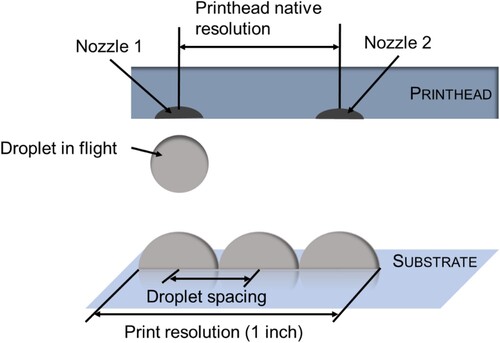
It is worth stating, that the property droplet spacing is controlled by the parameter print resolution. The print resolution set for a print pattern normally equals to the resolution of the image, based on which the printhead performs the printing. In the case of the image, the term image resolution defines the centre-to-centre distance of two adjacent pixels of the image. Each pixel represents a potential physical droplet. Similarly, print resolution defines the centre-to-centre distance of two dispensed droplets (), if all pixels on the image are assigned to a physical droplet. Print resolution is normally stated in the unit dots per inch (dpi). In , for example, three droplets are displayed within one inch which equals to a print resolution and drop distance of 3 dpi and 0.846 mm, respectively. Therefore, the parameter print resolution defines the smallest distance of two deposited droplet. The distance between two actually deposited droplets depends on the image, but will always be a multiple of the smallest distance as defined by the print resolution.
Figure 1. Schematic illustration of the relation of print resolution and centre-to-centre droplet distance in inkjet printing.
Coverage percentage indicates the relative portion of pixels in the print image that corresponds to a printed ink droplet in the physical image. This could be facilitated by a dithering technique applied on the print pattern in order to remove some of the printed pixel [Citation52]. This bi-level image processing technique is also referred to as ‘dithering’ or ‘halftoning’ in the print industry [Citation64]. Zhou and Chen proposed a halftoning process for three-dimensional inkjet printing that enables printing at larger layer thickness while keeping the high accuracy of slanted geometry and smooth surface, hence, also reducing the manufacturing time considerably [Citation65]. Ostromoukhov et al. introduced a dithering algorithm which deploys a variation of the intensity of particular pixels in order to further improve the quality of halftone prints [Citation51]. Morsy et al. reported to use shape dithering to reduce the staircase-effect visible in 3D printed parts, thus improving the surface quality and accuracy [Citation66].
Looking at the previous review, one can say that although numerous studies related to 3D inkjet printing and 2D inkjet printing have been conducted, the majority of the studies is focusing on a single or a limited number of parameters.
In particular, individual printing parameters such as waveform, UV-curing behaviour and droplet/substrate interaction on the print quality have been looked into, while their interactions with one another have been studied partially.
The effects of these controlling parameters and/or their joint impact on inkjet-printed 3D structures are important to know and therefore should be systematically examined. Understanding and being able to quantitively evaluate the effects of these parameters offers the possibility to precisely control and to deliver consistent and effective fully cured printed layers and components. In this context, the objective of this research study is to bridge this gap. This study analyses experimentally the effect of five printing parameters, namely print resolution and coverage percentage of the image, droplet volume, printing speed and UV-curing power and their interaction effects on the printed layer height for a better understanding and precise control of the printing process.
2. Materials and methods
2.1. 3D inkjet printer and ink
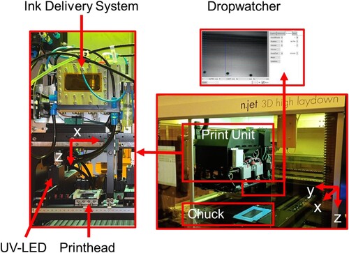
The studies were conducted on the printer ‘n.jet 3D high laydown’ by Notion Systems as shown in . The printer contains a ‘Xaar 1003’ piezoelectric inkjet printhead which jets from 1000 nozzles, 500 each row, and possesses a nominal native resolution of 360 dpi. The printer comprises of three axes in x-, y- and z-direction, allowing the printer to generate 3D structures by moving the printhead unit in print direction (z-axis) after one layer (x–y plane) has been completed. In this system, the chuck with the substrate are in motion during printing while keeping a print distance of 800 µm to the printhead nozzle plate. The curing takes place between each swathe and is facilitated by the UV-LED lamp FireEdge™ FE400 by Phoseon-Technologie at a wavelength of 385 nm. The ink is delivered to the printhead through the recirculation system ‘Midas 950’, which keeps the ink constantly moving and supports in maintaining a steady temperature of the ink. The acrylic polymer-based UV-curable ink SPJ 1071 was provided by BASF and is heated up to 60°C during printing to lower the viscosity to 14.65 mPas to guarantee jettability. The ink’s density at room temperature is 1.076 g/cm3. The printer itself is also equipped with a drop watcher which enables in-flight droplet measurement such as droplet volume and droplet velocity.
Figure 2. 3D inkjet printer by Notion Systems: n.jet 3D high laydown.
2.2. Design of experiments
Following five process parameters were investigated during this study with regard to their effect on printed layer height: print resolution, coverage percentage, droplet volume, printing speed and UV-Power. outlines the investigated five levels in this study for each process parameter. Fifty-two printing trials designed based on the Central Composite Design were conducted, which are displayed in . Each printing trial has been repeated twice.
Table 1. Examined printing parameters.
Table 2. Overview of the printing trials designed based on the central composite design.
The lower limit of print resolution in this experiment is defined by the native resolution, which is defined by the manufactured nozzle-to-nozzle distance of the printhead. This printhead nominal native resolution is 360 dpi (nozzle-to-nozzle distance 70.5 µm) and at this resolution, there is still an overlap of the droplet guaranteed as the centre-to-centre distance of the deposited droplet is less than the droplet diameter (droplet volume of 26.85 pl results in a droplet of 87 µm diameter on the PET substrate). The float number of the set print resolution values deviating from the nominal values takes the manufacturing intolerance of the nozzle-to-nozzle distance for this particular printhead into account. The distribution of the pixels not assigned to a physical droplet (setting: coverage percentage) was determined at random. No values below 80% were chosen due to the voids appearing in the printed geometries. The drop volume of a single droplet can be varied by setting the greyscale level. This particular printhead enables up to 8 greyscale levels. The resulting droplet volume is defined by the printhead waveform and ink properties. Moreover, the highest achievable drop volume for this particular print setup is 64 pl which defines the upper limit of this experiment. Droplets below 26 pl were not considered in this study as small droplets can be subject to considerable unstable printing behaviour due to the aerodynamic drag effect and the motion of the chuck. Printing speed or print velocity refers to the velocity of the chuck which moves beneath the stationary printhead during printing. Print velocities between 100 and 300 mm/s were chosen as these values are normally set in order to achieve high throughput 3D printing. UV-Power, given in Watt, refers to the power setting of the UV-LED lamp during the curing process. The maximum output power of the used UV-LED lamp is 20 W, hence 8 W corresponds to a UV-Power setting of 40%. The ink supplier recommended a curing of at least 40% of UV-Power for a proper crosslinking of this ink, which defines the lower bound.
2.3. Test specimen
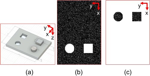
The total area of the printed specimen is 10 mm × 7 mm and 1 mm height and contains two circular and two square structures and comprises of 40 layers. It has to be noted that the 20 layers of cavities ((b)) and 20 layers of pillars ((c)) visible in this specimen ((a)) are intended for a future study on lateral dimensions, therefore is not part of the investigation of this study and will not be further described. The focus of the study lies on the layer thickness of the main body of this specimen, which comprises 20 layers ((b)). First, the specimen was designed as a three-dimensional model with the CAD-software Autodesk Inventor. The model of the test sample (all measurements are in millimetre) is displayed in (a). The model was then converted into a series of TIFF-images (Tagged-Image File Format) by deploying a python script and the open-source program 3DSlicer in order to be processable by the printer.
Figure 3. CAD-model of the test specimen (1000 mm × 700 mm) (a) and examples of (b) TIFF-Images for layer number 1–20, coverage percentage 90% and (c) layer number 21–40, coverage percentage 90%.
2.4. Metrology
The layer height was measured with the dial gauge MarCator 1086 R by Mahr with a measuring resolution of a half-micron range. The repeatability accuracy of the dial gauge is 1 µm. Measuring the layer thickness of these translucent specimens with an optical microscope proved to be unreliable as the optical microscope was not able to detect the surface in a reliable way with the available light illusion settings. The specimen was placed on the measurement plate and the dial gauge, fixed to the measurement plate in a 90° manner, approached the specimen from the top until it touches the surfaces.
3. Results
3.1. Overview
The layer height of each parameter set is shown in . The 10 measurements marked as central points positioned in the centre of the graph represent the parameter sets containing the middle value of every parameter. The experimental trials are considered highly robust which is proven by the small variation of both the central points and the standard deviation. The measured average layer heights of all 52 print trials range from 4.73 µm to 98.58 µm (). The highest printed layer heights were all achieved at a resolution of 1441.13 dpi and a low printing speed of 142.04 mm/s. The coverage percentage of the five highest results ranges from 84.20% to 95.80%. The parameters drop volumes of 38 and 55.75 pl and UV-Power of 10.52 W and 17.48 W contributed to the results of the highest layer height. An image of the specimen with the largest layer height is displayed on the right top corner. The five lowest values, on the other hand, were generated from lower values of resolution (720.57 and 360.28 dpi) and of droplet volume (38, 47 pl), mid-range coverage percentage (84.20%, 95.80%, 90%), and a high printing speed (257.96 and 200 mm/s). In the right bottom corner, an image of such sample is shown.
Figure 4. Average printed layer height (n = 2) of samples printed at various printing conditions and images of the specimens of the print trials #32 and #48 with the largest and lowest layer thickness (corresponding data points marked with a red dotted circle).
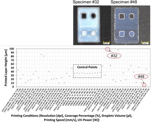
Table 3. Corresponding print settings and measured layer thickness of the printed samples (CP = central Points). Table entries are listed in correspondence to the order in (first row equals to the left data point on the x-axis).
3.2. Statistical analysis of layer height
To get a clearer understanding on the interaction between process parameters and their effect on the layer height, the statistical quadratic regression model was created using MATLAB (R2020a). It was done by modifying the second-order polynomial function seen in Equation (1) to fit the measured data.
(1)
(1) Here, ‘y’ is the response, which is the printed layer height, and ‘b0’, ‘bi’, ‘bii’ and ‘bij’ are the regression coefficients or predictors, with ‘xi’, being the value of the ith factor printing resolution, coverage percentage, droplet volume, printing speed and UV-Power.
To identify the most significant parameters affecting printed layer height, analysis of variance (ANOVA) was conducted. Significance is characterised through the p-value in the ANOVA. A p-value below 0.05 indicates a significant parameter, while a p-value less than 0.01 indicates a highly significant parameter.
The quadratic regression model developed for the printed layer height based on the 5 process parameters looked upon proposed 21 terms. Out of these 21 terms, only coefficients with a high significance, meaning a p-value of under 0.01 were considered. Equation (2) shows this model.
(2)
(2) where ‘rnorm’ is the normalised printing resolution, ‘cpnorm’ is the normalised coverage percentage, ‘dvnorm’ is the normalised droplet volume, ‘psnorm’ is the normalised printing speed and ‘uvnorm’ is the normalised UV-Power, although the latter one is not included in this equation, as the effect was not significant. This model created has a coefficient of determination of R2 = 96% (adj. R2 = 93%). The three most significant parameters were identified using ANOVA: The most significant is printing resolution, with a p-value of 5.2588e-17, the second most significant being printing speed, with a p-value of 1.6763e-13 and the third most significant being droplet volume, with a p-value of 3.5699e-13.
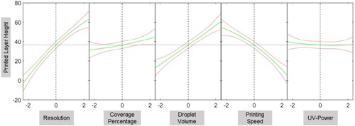
The predictor plot seen in examines the effects of the parameters on the layer height. It becomes clear, that resolution has a significant influence on layer height, with increased resolution leading to thicker layers. This behaviour is also quantified in Equation (2) with rnorm having the highest coefficient among all significant parameters. The effect of droplet volume is very similar, but not as pronounced as resolution. Droplet volume is shown to be the third most significant parameter and thus has a decisive effect on the layer height. Printing speed has an inverted effect on layer height, with increasing printing speeds causing lower layer heights. Printing speed, being the second most significant parameter, has been shown to have a strong effect on the printed layer height. Coverage percentage also correlates positively with the layer height, but to a much smaller degree, with higher coverage percentages leading to slightly higher layer thickness. UV-Power, on the other hand, has barely no effect on the layer height for the given range, although a slight rise can be seen for the lower values, implying that the layer thickness is larger at lower UV-Power, which could be explained by a less degree of shrinkage when exposed to less UV-radiation. The effect of UV-Power is described by a p-value of 0.47248 and is therefore considered insignificant as proven by the ANOVA. Hence, UV-Power is assumed to have no effect on the layer height. The following Sections elaborate on the results obtained in this study.
Figure 5. Effect of each parameter (normalised value) on the printed layer height.
3.3. Effect of resolution on layer height
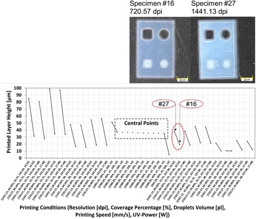
In each connected value set represents a trial pair in which only the resolution has been changed while the other parameters are kept constant. The left data value of each pair shows the result of the higher resolution. By looking at the pairs of print trials in which only the resolution of the TIFF-image has been changed, it was observed that a higher resolution leads to a higher layer thickness, although the degree of the changes varies as a function of the other parameters. On the right side, two such specimens which were regarded as one print trial in this study (print trials #27 and #16) are shown. The top specimen was printed with a print resolution of 1441.13 dpi, while the bottom one was printed with approximately half the resolution (720.57 dpi). Both specimens were printed with a print speed of 257.96 mm/s, drop volume of 55.75 pl, coverage percentage of 84.20% and UV-Power of 10.53 W. Based on the degree of translucency, it can be visually assessed that print trial #27 resulted in a greater layer height compared to print trial #16 which aligns with the measured layer height values.
Figure 6. Effect of print resolution on printed layer height (n = 2) and images of the specimens of the print trials #27 and #16 (corresponding data points marked with a red dotted circle, for detailed parameter values see ).
3.4. Effect of coverage percentage on layer height
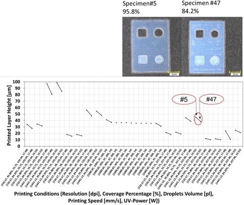
illustrates the results of the 52 trials arranged in a way that two neighbouring data points only differ in their coverage percentage. For every set of parameters, it has been observed that a higher coverage percentage, which is in this plot always the left data of each pair, results in a greater layer height. On the right side, the trial pairs #5 (coverage percentage 95.8%) and #47 (coverage percentage 84.2%) are displayed. The remaining print parameters were unchanged, which are 720.57 dpi print resolution, drop volume 38 pl, print speed 257.96 mm/s and UV-Power 10.52 W. Not much difference is visible which is to be expected since the difference in layer height is rather minor. The measured layer height of print trial #5 is 11.6 µm while the one of #47 is 10.175 µm.
Figure 7. Effect of coverage percentage on layer height (n = 2) and images of the specimens of the print trials #5 and #47 (corresponding data points marked with a red dotted circle, for detailed parameter values see ).
3.5. Effect of droplet volume on layer height
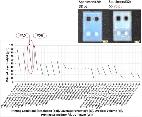
Each pair of print trials in represents two specimens which differ in their applied droplet volume while the other print conditions remain the same. The left value always represents the response of the specimen printed with a larger droplet volume. The trend visible in this Figure indicates that a higher droplet volume leads to a thicker layer and can be confirmed by the print specimens displayed on the right side. The top specimen printed with a droplet volume of 55.75 pl contains a greater amount of material compared to the bottom specimen, as it can be seen by the wavy surface indicating an excessive material deposition. The other unchanged print parameters of these specimens were print resolution 1441.13 dpi, coverage percentage 95.8%, print speed 142.04 mm/s and UV-Power 17.48 W.
Figure 8. Effect of droplet volume on layer height (n = 2) and images of the specimens of the print trials #32 and #28 (corresponding data points marked with a red dotted circle, for detailed parameter values see ).
3.6. Effect of printing speed on layer height
The next contains again all the experimental results, arranged in a way that each pair of print trials, connected with a line, vary only in terms of the print speed. Here, it has to be especially noted that the left dataset of each trial pair corresponds to a lower printing speed value. Hence, an inverse correlation of printing speed and printed layer height is present which means that a lower printing speed leads to greater layer thickness.
Figure 9. Effect of printing speed on layer height (n = 2) and images of the specimens of the print trials #25 and #17 (corresponding data points marked with a red dotted circle, for detailed parameter values see ).
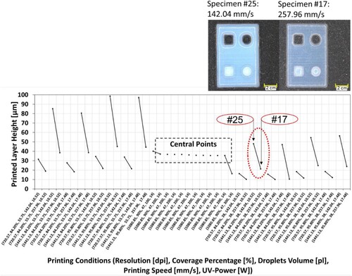
The printing speed appears to have a large impact on the layer height, being nearly on par with the droplet volume. In other words, the change of printing speed caused a change in the total amount of deposited ink. The images of the specimens on the right side of show this correlation clearly. The bottom image, printed at 257.96 mm/s print speed, appears much more translucent, indicating a lower layer height compared to the top specimen printed at 142.04 mm/s.
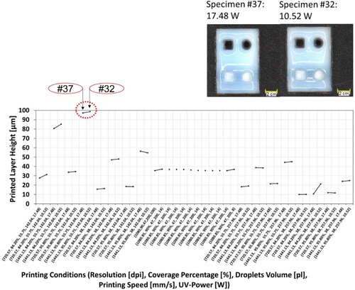
3.7. Effect of UV-Power on layer height
In , the left set of parameters of each pair represents the data where higher UV-Power has been applied for curing the layer. Not only does this parameter have a minor effect on the layer height, but the change is also inconsistent. For some trial pairs, the higher UV-Power created a higher layer thickness, while other pairs resulted in a thinner layer. These findings lead to the conclusion, that the UV-Power settings used in this study for this particular print setup do not have any reliable and significant effect on the layer height. This can be also confirmed in the specimens displayed in which are printed at UV-Power 17.48 and 10.52 W, while the other parameters remained constant (1441.13 dpi, 95.8% coverage percentage, 55.75 pl drop volume and print speed 142.04 mm/s).
Figure 10. Effect of UV-Power on layer height (n = 2) and images of the specimens of the print trials #37 and #32 (corresponding data points marked with a red dotted circle, for detailed parameter values see ).
3.8. Two-factors interaction effect on printed layer height
displays the interaction effects of two parameters on the printed layer height. In general, the interacting effect between UV-Power and the other parameters is shown to be insignificant, indicated by overlapping curves in the corresponding plots ((h,j,p,t)).
Figure 11. Effect of interaction of printing parameters on printed layer height.
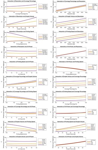
The first two figures in the top row of illustrate the interaction effect of coverage percentage and resolution. (a) shows clearly the significant effect of resolution on the layer height, which becomes even slightly more dominant under higher coverage percentage, indicated by the increased steepness of the curves at the higher domain. In the opposite plot, (b), the coverage percentage exerts a constant and less significant effect on the layer height over the entire range of the given resolution.
A quite similar trend can be seen when looking at the graphs in the second top row of , presenting the effect of resolution and droplet volume on the printed layer height. (c) clearly demonstrates that resolution has, again, a significant effect on the printed layer height, which even enhances with higher droplet volumes. For the right-hand plot, (d), it can be concluded that droplet volume has a consistent significant effect on layer height for the entire range of resolution.
(e,f) examine the interaction effect of resolution and printing speed. Resolution clearly shows a significant effect on the printed layer height, which lessens under higher printing speeds ((e)). Printing speed, on the other hand, shows a noticeable constant significant effect on the printed layer height ((f)).
The interaction effect plot of UV-Power and resolution on the printed layer height are depicted in the fourth row of . Interestingly, a different trend compared to the previous plots is visible. The curves displayed in (g) indicate that there is a significant effect of resolution on the printed layer height with a subtle reduction at higher UV-Power range.
The same trend is also visible in the next graphs which plot the interaction of UV-Power and printing speed on printed layer height ((i,j)). Print speed demonstrates an almost constant significant effect on printed layer height which slightly diminishes for higher UV-Power values ((i)).
In (k,l) the interaction effect between coverage percentage and droplet volume on the printed layer height is shown. Based on the curves in (k) it can be derived that coverage percentage has an effect on printed layer height which is further reinforced by higher droplet volumes. From the reverse plot ((l)), it can be concluded that the droplet volume has a constant significant effect on layer height over the whole range of coverage percentage.
From the row with (m,n), one can detect that coverage percentage affects the layer height significantly, however the effect becomes less when approaching a higher printing speed. In the opposite plot, the effect of significant printing speed on the printed layer height is clearly visible and increases even more at higher coverage percentage.
(o,p) depict the interaction of coverage percentage and UV-Power on the printed layer height. The effect of coverage percentage on the printed layer height as shown in (o) is significant and reduces slightly at higher UV-Power.
The interaction plots of droplet volume and printing speed in the second to the last row of indicate that both drop volume and printing speed have a non-linear significant effect on the printed layer height. The considerable effect of droplet volume on layer height (q) decreases when moving towards higher printing speed, while the effect of printing speed (r) increases for a higher droplet volume.
In the last row in , the left plot shows almost three parallel lines, implying a nearly constant significant effect of droplet volume on layer height over the investigated range of UV-Power ((s)).
4. Discussion
Printing resolution, drop volume, and coverage percentage have been determined to correlate positively with the printed layer height. Print resolution is defined by the droplet centre-to-centre distance. Consequently, the higher the resolution, the closer the droplets are being deposited next to each other and the greater the layer height. This behaviour can be explained on the droplets level. The coalescence of two droplets generally undergoes three phases: (1) the generation and growth of a liquid bridge between the drops, (2) the contact line moves and relaxation of the liquid bridge, (3) the elliptical shape of the drop takes on a circular shape after relaxation [Citation67]. The resulting semiwidth () of the liquid bridge is not only governed by the coalescence time, volume/radius of the droplet and contact angle, but also by the viscosity and the initial distance between the droplets [Citation67–69]. Sellier and Trelluyer computed that the semiwidth of the bridge increases the closer two droplets are placed [Citation67]. The liquid bridge height is proportional to the liquid bridge semiwidth [Citation67]. Therefore, a closer distance between two droplets leads to an increased layer height, as each layer essentially consists of the coalescence of multiple droplets.
Figure 12. Two droplets coalesce while creating a liquid bridge.
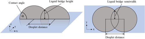
The chosen print resolutions (720 dpi to 1441 dpi) in this study resulted in theoretical center-to-center distances of the droplets between 17.63 µm to 35.28 µm, while the smallest droplet volume of 26 pl already resulted in a droplet radius on the PET substrate of 43.5 µm. Considering these applied settings, the droplets were printed close enough to be in contact, confirming that even with the largest droplet positioning gap (35.28 µm) and smallest droplet radius (43.5 µm) droplet coalescence still took place.
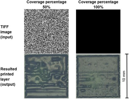
Coverage percentage defines the portion of droplets/materials within the TIFF-image that are assigned to a printed droplet. A reduced coverage percentage means that not all pixels assigned to a printed pixel in the image is being printed by the printer. Hence, for a coverage percentage below 100% some randomly selected pixels are not printed, increasing the distances between some adjacent droplets and reducing the total volume of applied material. For clarification purpose, this relation is demonstrated in which shows samples printed using 50% (left) and 100% (right) coverage percentages. The square specimen with the lower covering percentage on the left side displays some voids as a result of the non-printed pixels. The square specimen on the right side with full coverage displays a nearly spotless square.
Figure 13. TIFF image input and resulted printed squared pattern (size 10 mm × 10 mm, 1 layer) with 50% and 100% coverage percentages printed with a resolution of 360 dpi.
The layer height of print trial #5 and #47 displays a relative reduction of layer height (12.28%) which is close to the relative change of coverage percentage (12.10%). The similarity of change confirms the explanation, as for the same width and length and assuming that the volume is conserved, the height has to change.
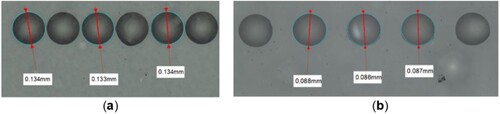
The observed positive correlation between droplet volume and printed layer height can be explained by the fact that the equilibrium size of a droplet on a substrate is primarily governed by the drop volume and the contact angle between the substrate and the liquid material [Citation53]. As a result, provided that the print resolution and, thus, the centre-to-centre distance remains unchanged, the portion with which two droplets overlap is defined by the droplet diameter size on the given substrate (first layer substrate is PET foil, for all subsequent layers it is the UV-cured layer). Hence, an increased droplet volume, which is the case for the left specimen shown in , and assuming that the contact angle remains constant (no change of substrate), results in a larger droplet radius. This leads to a greater degree of overlapping of these droplets. Subsequently, the similar relation as pointed out for the print resolution applies here as well: the closer the droplets are deposited, the higher the resulting liquid bridge between them, the higher the generated layer. In this study, the corresponding size of the droplets on the PET foil for the droplet volumes 64 and 26.85 pl were 133.67 and 87 µm, respectively ().
Figure 14. Diameter of droplets on PET-substrate with a droplet volume of (a) 64 pl, average droplet diameter 133.67 µm; and (b) 26.85 pl, average droplet diameter 87 µm.
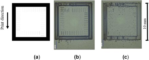
Printing speed, on the other hand, has an inverted effect on layer height. For elaborating purpose and to investigate this phenomenon, the following test prints conducted at 100 mm/s ((b)) and 300 mm/s ((c)) print speed were printed. The structures show that the delicate pattern inside the frame becomes undistinguishable with higher print speed. Misting and missing lines have been observed as well for the structure printed at higher chuck velocity, even though the same print settings and print image ((a)) have been used. In addition to it, the frame printed at 300 mm/s contains less material, which matches the observation of the print trials. Interestingly, misting of the frame pattern is only visible beneath the end of a printed structure in print direction, most likely caused by satellite drops. Both printed patterns exhibit fuzzy wavy boundaries on the first printed edge (lower edge).
Figure 15. Comparison of samples printed at different printing speeds; (a) TIFF-Image, size 10 mm × 10 mm, (b) sample printed at printing speed 100 mm/s, (c) sample printed at printing speed 300 mm/s.
In the literature, it has been reported that the misplacement of droplets exacerbates if the throw distance (distance between nozzle plate and substrate) is increased and/or the drop volume becomes less. This behaviour is caused by the aerodynamic drag forces, which decelerate a droplet while travelling, in addition to the movement of the chuck generating wakes and air turbulences in the area between the substrate and the printhead [Citation45,Citation46,Citation70,Citation71]. These two phenomena could be one reason for the misplacement of the droplets within the frame, deflecting the travelling droplets. However, the expected print defects from these deflected droplets should have appeared perpendicular to the chuck movement, which Mallinson et al. named ‘Tiger Stripes’ [Citation72]. This, however was not visible in our case. shows clear-cut edges along the print direction, which makes the following hypothesis more likely: the substantial decrease of the total deposited material volume could be caused by the actual print frequency present during the printing of this particular pattern. A stable print frequency is not only limited by the maximum theoretical firing frequency given by the printheads’ technical specification, but also by the ink properties. Stable printing can only be achieved if the residual meniscus oscillation is fully suppressed before firing the next droplet. A proper meniscus oscillation dampening can only be achieved by a finely tuned waveform with regards to its shape, amplitude and its duration of the respective section such as dwell time, rising and falling time, which together determine the actual maximum print frequency [Citation73,Citation74]. By looking at the present print frequencies of the print trials in , it is clear that the actual firing frequencies changed across the print trials and covered a range from 2.84 to 14.63 kHz. Most likely, the jetting performance was subject to variations due to the changed droplet volumes at the selected print frequencies or because the maximum jetting frequency for this ink has been exceeded, resulting in instable drop formation such as smaller drop volumes due to misting and satellite drops.
Table 4. Corresponding print frequencies of this study at various print velocities and print resolution.
UV-Power has barely no effect on the layer height for the given range, although a slight rise can be seen for the lower values, implying that the layer thickness is larger at lower UV-Power, which could be explained by a less degree of shrinkage when exposed to less UV-radiation. The effect of UV-Power is described by a p-value of 0.47248 and is therefore considered insignificant as proven by the ANOVA.
The highest possible printed layer height can therefore be achieved by setting the parameters printing resolution, droplet volume and coverage percentage to the maximum value, while printing speed should be set to the minimum value. UV-Power has no effect within the investigated parameter range and thus does not need to be considered, but the UV-Power value should be chosen carefully in order to fully cure the deposited ink. In this case, a UV-Power of 8 W was enough to cure the sample. In case of this study, the parameter set of resolution 1801.42 dpi, coverage percentage 100%, droplet volume 64 pl and printing speed 100 mm/s would result in the highest printed layer.
With print resolution having the most significant effect on layer height, this parameter can be first addressed, when aiming for thick layers. When time is a constraining factor, higher print speeds can be applied. This study shows that printing speed could be increased to a certain degree to maximise the throughput without a major decrease on layer height or print quality. However, the printing speed should not exceed 200 mm/s, as higher speeds proved to be unreliable in printing. For accurate applications, deploying a lower printing speed might be beneficial as it ensures detailed droplet placement.
Droplet volume and coverage percentage could be lowered to a certain degree to lower consumption of ink and decreasing the production cost, without reducing the layer height considerably. To achieve a cost-effective printing environment, a print resolution, droplet volume and coverage percentage of 1080.85 dpi, 47 pl and 90%, respectively, is proposed. This set of parameter ensures sufficient high layers, but less ink printed, compared to when printing with higher values.
It should be noted that a decreased layer height raises the overall number of layers to achieve the same height of the printed part. Although a lower layer height is beneficial for achieving high geometrical fidelity in z-direction and reduces the amount of ink consumed, this gain could be reduced by the increased number of layers. This interdependence ought to be considered and requires further investigation in future works.
5. Conclusion
This study aimed to investigate how the five process parameters, printing resolution, coverage percentage, droplet volume, printing speed and UV-Power affect the printed layer height. Following conclusion has been derived from this study:
Printing resolution is the most impactful one on obtainable layer height, followed by printing speed and droplet volume.
The higher the printing resolution, droplet volume or coverage percentage, the greater the obtained layer height. However, the positive relation of coverage percentage and layer height is the least pronounced one in this list.
Printing speed has an inverse effect on layer height, leading to a decrease of layer height when increasing the printing speed.
UV-Power has been the only parameter that does not show any significant effect on layer height. Most likely, the investigated UV-Power considered was in a range where the degree of photopolymerisation of the ink reached its maximum or the ink used in this study is inherently less prone to shrinkage.
UV-Power also has no noteworthy effect on layer height when interacting with other parameters.
Interactions between parameters influence layer height in various ways:
o The significant effect of print resolution on printed layer height is considerably enhanced when applying higher coverage percentage or higher drop volume, but largely reduced at higher print speed and slightly decreased for higher UV-Power.
o The significant effect of coverage percentage on printed layer height remains constant over the entire range of printing resolution, but is slightly enhanced when applying higher droplet volume or higher UV-Power. A higher print speed, on the other hand, slightly diminishes the effect of coverage percentage on layer height.
o The significant effect of drop volume on layer height is consistent for all resolution and coverage percentage values, but is strongly reduced at higher print speed and slightly decreased for higher UV-Power.
o The significant effect of print speed on layer height remains unchanged for all resolution settings, while an increased coverage percentage or larger drop volume enhances the effect of print speed on layer height, whereas a higher UV-Power reduces this effect.
o The effect of UV-Power on printed layer height is considered insignificant for all interactions with other parameters.
The greatest layer height could be obtained with a print resolution of 1441.13 dpi, 95.8% coverage percentage, 55.75 pl droplet volume, 142.04 mm/s print velocity and 10.52 W UV-intensity.
For a cost-effective printing condition, a print resolution, droplet volume and coverage percentage of around 1080.85 dpi, 47 pl and 90%, respectively is suggested. This set of parameter presents the greatest possible layer height, while consuming the least amount of ink.
Future research could include a more detailed examination of the effect of the process parameters on the lateral dimensions and feature resolution. Further investigations are required in order to fully understand the underlying mechanism for the decrease of the layer height at higher printing speed. It is recommended to conduct a detailed analysis of the droplet volume over the whole frequency range and to perform drop watching at the actual print frequency to assess the quality of the droplet formation. The aerodynamic effect on jetting behaviour could be the reason for the fuzzy top edges of a print pattern and should be investigated in the future. It is also suggested to try out the approach of printing a sacrificial leader bar above the actual print pattern in order to ‘warm-up’ the nozzles to improve the print quality. Furthermore, an analysis of the efficiency and repeatability of the process parameters to observe the 3D inkjet printing process in terms of economic viability is of high importance as well. The effect of UV-Power on the printed layer height should be further investigated by expanding the range of examined UV-Power values in order to capture the effect of under- and over-curing. The impact of viscosity on the resulting layer height ought to be investigated as well. Once the relevant process parameters are known, more elaborate approaches to optimise process parameters or to establish a model for predicting the optimal process outcomes by means of machine learning approaches shall be applied. Overall, 3D inkjet printing as promising as it is, still requires further research in terms of accuracy and viability in the smallest scales possible, to fully cement it as the manufacturing method of the future.
Acknowledgements
The authors gratefully acknowledge the support of Leander Verbelen and Marta Ruscello from BASF 3D Printing Solutions GmbH, Germany who provided free samples of the SPJ 1071 ink used to conduct the 3D printing trials. The authors would like to acknowledge the support provided by the KIT-Publication Fund of the Karlsruhe Institute of Technology.
Disclosure statement
No potential conflict of interest was reported by the author(s).
Additional information
Funding
References
- ISO/ASTM52900:21 Additive manufacturing – General principles – Fundamentals and vocabulary. ISO, 2021-11 2021. [Online]. Available from: https://www.astm.org/f3177-21.html.
- Ivorra-Martinez J, Peydro MÁ, Gomez-Caturla J, et al. The effects of processing parameters on mechanical properties of 3D-printed polyhydroxyalkanoates parts. Virtual Phys Prototyp. 2023;18(1), doi:10.1080/17452759.2022.2164734
- Xiao Z, Yu W, Fu H, et al. Recent progress on microstructure manipulation of aluminium alloys manufactured via laser powder bed fusion. Virtual Phys Prototyp. 2022;18(1), doi:10.1080/17452759.2022.2125880
- Wang W, Zhang G, Huang H, et al. Large-scale material extrusion-based additive manufacturing of short carbon fibre-reinforced silicon carbide ceramic matrix composite preforms. Virtual Phys Prototyp. 2023;18(1):113–123. doi:10.1080/17452759.2023.2245801
- Zhang K, Meng Q, Zhang X, et al. Quantitative characterization of defects in stereolithographic additive manufactured ceramic using X-ray computed tomography. J Mater Sci Technol. 2022;118:144–157. doi:10.1016/j.jmst.2021.11.060
- Angmo D, Larsen-Olsen TT, Jørgensen M, et al. Roll-to-roll inkjet printing and photonic sintering of electrodes for ITO free polymer solar cell modules and facile product integration. Adv Energy Mater. 2013;3(2):172–175. doi:10.1002/aenm.201200520
- Bhansali US, Khan MA, Alshareef HN. Organic ferroelectric memory devices with inkjet-printed polymer electrodes on flexible substrates. Microelectron Eng. 2013;105:68–73. doi:10.1016/j.mee.2012.12.024
- Qu P, Xiong D, Zhu Z, et al. Inkjet printing additively manufactured multilayer SOFCs using high quality ceramic inks for performance enhancement. Additive Manufacturing. 2021;48:102394. doi:10.1016/j.addma.2021.102394
- Duffy GL, Liang H, Williams RL, et al. 3D reactive inkjet printing of poly-ε-lysine/gellan gum hydrogels for potential corneal constructs. Mater Sci Eng C, Mater Biol Appl. 2021;131:112476. doi:10.1016/j.msec.2021.112476
- Chu B, He J-m, Wang Z, et al. Proangiogenic peptide nanofiber hydrogel/3D printed scaffold for dermal regeneration. Chem Eng J. 2021;424:128146. doi:10.1016/j.cej.2020.128146
- Dufour A, Gallostra XB, O’Keeffe C, et al. Integrating melt electrowriting and inkjet bioprinting for engineering structurally organized articular cartilage. (in eng), Biomaterials. 2022;283:121405. doi:10.1016/j.biomaterials.2022.121405
- Adamski K, Kawa B, Walczak R. Inkjet 3D Printed Venturi Microflowmeter. 2018 XV International Scientific Conference on Optoelectronic and Electronic Sensors (COE): IEEE, 2018, p. 1–3.
- Walczak R, Adamski K, Kubicki W. Inkjet 3D printed modular microfluidic chips for on-chip gel electrophoresis. J Micromech Microeng. 2019;29(5):057001. doi:10.1088/1361-6439/ab0e64
- Bezek LB, Chatham CA, Dillard DA, et al. Mechanical properties of tissue-mimicking composites formed by material jetting additive manufacturing. J Mech Behav Biomed Mater. 2022;125:104938. doi:10.1016/j.jmbbm.2021.104938
- Goh GD, Sing SL, Lim YF, et al. Machine learning for 3D printed multi-materials tissue-mimicking anatomical models. Mater Des. 2021;211:110125. doi:10.1016/j.matdes.2021.110125.
- Gülcan O, Günaydın K, Tamer A. The State of the Art of Material Jetting-A Critical Review. Polymers. 2021;13(16):2829. doi:10.3390/polym13162829
- Elkaseer A, Chen KJ, Janhsen JC, et al. Material jetting for advanced applications: a state-of-the-art review, gaps and future directions. Addit Manuf. 2022;60:103270. doi:10.1016/j.addma.2022.103270
- Magazine R, van Bochove B, Borandeh S, et al. 3D inkjet-printing of photo-crosslinkable resins for microlens fabrication. Addit Manuf. 2022;50:102534. doi:10.1016/j.addma.2021.102534
- Qian Q, Kamps JH, Price B, et al. 3D reactive inkjet printing of bisphenol A-polycarbonate. Addit Manuf. 2022;54; doi:10.1016/j.addma.2022.102745
- Saleh E, Woolliams P, Clarke B, et al. 3D inkjet-printed UV-curable inks for multi-functional electromagnetic applications. Addit Manuf. 2017;13:143–148. doi:10.1016/j.addma.2016.10.002
- Anelli S, Rosa M, Baiutti F, et al. Hybrid-3D printing of symmetric solid oxide cells by inkjet printing and robocasting. Addit Manuf. 2022;51:102636. doi:10.1016/j.addma.2022.102636
- Tran V-T, Wei Y, Du H. Influence of thermal treatment on electronic properties of inkjet-printed zinc oxide semiconductor. Int J Smart Nano Mater. 2022;13(2):330–345. doi:10.1080/19475411.2022.2084172
- Song O, Rhee D, Kim J, et al. All inkjet-printed electronics based on electrochemically exfoliated two-dimensional metal, semiconductor, and dielectric. npj 2D Mater Appl. 2022;6(1):64. doi:10.1038/s41699-022-00337-1
- Mu B, Xu Y, Xu J, et al. Inkjet direct printing approach for flexible electronic. Res Eng. 2022;14; doi:10.1016/j.rineng.2022.100466
- Ball AK, Roy SS, Kisku DR, et al. Optimization of drop ejection frequency in EHD inkjet printing system using an improved Firefly Algorithm. Appl Soft Comput. 2020;94; doi:10.1016/j.asoc.2020.106438
- Das R, Ball A, Roy SS. Optimization of E-Jet based micro-manufacturing process using desirability function analysis, 2018, p. 477–484.
- Ball AK, Roy SS, Kisku DR, et al. A new approach to quantify the uniformity grade of the electrohydrodynamic inkjet printed features and optimization of process parameters using nature-inspired algorithms. Int J Prec Eng Manuf. 2020;21(3):387–402. doi:10.1007/s12541-019-00213-x
- Das R, Ball AK, Roy SS. Application of PCA-based hybrid methodologies for parameter optimization of E-jet based micro-fabrication process: a comparative study. J Braz Soc Mech Sci Eng. 2018;40(9), doi:10.1007/s40430-018-1373-4
- Ball AK, Das R, Roy SS, et al. Experimentation modelling and optimization of electrohydrodynamic inkjet microfabrication approach: a Taguchi regression analysis. Sādhanā. 2019;44(7), doi:10.1007/s12046-019-1146-5
- Han Y, Wei C, Dong J. Super-resolution electrohydrodynamic (EHD) 3D printing of micro-structures using phase-change inks. Manuf Lett. 2014;2(4):96–99. doi:10.1016/j.mfglet.2014.07.005
- Derby B. Inkjet printing of functional and structural materials: fluid property requirements, feature stability, and resolution. Annu Rev Mater Res. 2010;40(1):395–414. doi:10.1146/annurev-matsci-070909-104502
- Hoath SD, Hutchings IM, Martin GD, et al. Links between Ink rheology, drop-on-demand Jet formation, and printability. J Imaging Sci Technol. 2009;53(4):041208-1. doi:10.2352/J.ImagingSci.Technol.2009.53.4.041208
- Braga RR, Ballester RY, Ferracane JL. Factors involved in the development of polymerization shrinkage stress in resin-composites: a systematic review. Dental Mater: Official Publication of the Academy of Dental Materials. 2005;21(10):962–970. doi:10.1016/j.dental.2005.04.018
- Ledesma-Fernandez J, Tuck C, Hague R. 3D high viscosity jetting of functional materials, 2016, p. 41–47.
- Pierrel J, Ibrahim A, Croutxé-Barghorn C, et al. Effect of the oxygen affected layer in multilayered photopolymers. Polym Chem. 2017;8(31):4596–4602. doi:10.1039/C7PY00974G
- Pilkenton M, Lewman J, Chartoff R. Effect of oxygen on the crosslinking and mechanical properties of a thermoset formed by free-radical photocuring. J Appl Polym Sci. 2011;119(4):2359–2370. doi:10.1002/app.32650
- Duineveld PC. The stability of ink-jet printed lines of liquid with zero receding contact angle on a homogeneous substrate. J Fluid Mech. 2003;477:175–200. doi:10.1017/S0022112002003117
- Yang J, Zheng F, Derby B. Stability of lines with zero receding contact angle produced by inkjet printing at small drop volume. Langmuir. 2021;37(1):26–34. doi:10.1021/acs.langmuir.0c01928
- Ibrahim M, Otsubo T, Narahara H, et al. Inkjet printing resolution study for multi-material rapid prototyping. JSME International Journal Series C. 2006;49(2):353–360. doi:10.1299/jsmec.49.353
- Ng WL, Huang X, Shkolnikov V, et al. Controlling droplet impact velocity and droplet volume: Key factors to achieving high cell viability in Sub-nanoliter droplet-based bioprinting. Int J Bioprint. 2022;8(1):424. doi:10.18063/ijb.v8i1.424
- Aqeel AB, Mohasan M, Lv P, et al. Effects of the actuation waveform on the drop size reduction in drop-on-demand inkjet printing. Acta Mech Sin. 2020;36(5):983–989. doi:10.1007/s10409-020-00991-y
- Cheng Y-L, Tseng T-W. Study on driving waveform design process for multi-nozzle piezoelectric printhead in material-jetting 3D printing. Rapid Prototyp J. 2021;27(6):1172–1180. doi:10.1108/RPJ-05-2019-0120
- Hamad AH, Salman MI, Mian A. Effect of driving waveform on size and velocity of generated droplets of nanosilver ink (Smartink). Manuf Lett. 2020;24:14–18. doi:10.1016/j.mfglet.2020.03.001
- Hor YL, Szabo Z, Lim HC, et al. Terahertz response of microfluidic-jetted three-dimensional flexible metamaterials. Appl Opt. 2010;49(8):1179–1184. doi:10.1364/AO.49.001179
- Rodriguez-Rivero C, Castrejón-Pita JR, Hutchings IM. Aerodynamic effects in industrial inkjet printing. J Imaging Sci Technol. 2015;59(4):40401-1–40401-10. doi:10.2352/J.ImagingSci.Technol.2015.59.4.040401
- Wang S. Aerodynamic Effect on Inkjet Main Drop and Satellite Dot Placement. NIP & Digital Fabrication Conference; 1998.
- Stringer J, Derby B. Formation and stability of lines produced by inkjet printing. Langmuir. 2010;26(12):10365–10372. doi:10.1021/la101296e
- Soltman D, Subramanian V. Inkjet-printed line morphologies and temperature control of the coffee ring effect. Langmuir. 2008;24(5):2224–2231. doi:10.1021/la7026847
- Jia X, Huang B, X W, et al. Study on the influence of printing conditions on the curing of UV ink. In: Gakkai NG, Sakai S, Benning P, Bruch X, Silence S, editors. NIP27: 27th international conference on digital printing technologies, S. Society for Imaging and Technology Eds. Springfield, Va.: IS & T Society for Imaging Science and Technology, 2011, pp. 399–401.
- Chen X, Ashcroft IA, Tuck CJ, et al. An investigation into the depth and time dependent behavior of UV cured 3D ink jet printed objects. J Mater Res. 2017;32(8):1407–1420. doi:10.1557/jmr.2017.4
- Zhao P, He Y, Trindade GF, et al. Modelling the influence of UV curing strategies for optimisation of inkjet based 3D printing. Mater Des. 2021;208:109889. doi:10.1016/j.matdes.2021.109889
- Elkaseer A, Schneider S, Deng Y, et al. Effect of process parameters on the performance of drop-On-demand 3D inkjet printing: geometrical-based modeling and experimental validation. Polymers. 2022;14(13):2557. doi:10.3390/polym14132557
- Meisel NA, Dillard DA, Williams CB. Impact of material concentration and distribution on composite parts manufactured via multi-material jetting. Rapid Prototyp J. 2018;24(5):872–879. doi:10.1108/RPJ-01-2017-0005
- Du Z, Lin Y, Xing R, et al. Controlling the polymer ink’s rheological properties and viscoelasticity to suppress satellite droplets. Polymer. 2018;138:75–82. doi:10.1016/j.polymer.2018.01.052
- Zhang Y, Hu G, Liu Y, et al. Suppression and utilization of satellite droplets for inkjet printing: a review. Processes. 2022;10(5):932. doi:10.3390/pr10050932
- Marangon F, Hsiao WK, Brenn G, et al. Satellite drop formation during piezo-based inkjet printing. 29th Conference on Liquid Atomization and Spray Systems. 2019.
- Mun RP, Byars JA, Boger DV. The effects of polymer concentration and molecular weight on the breakup of laminar capillary jets. J Nonnewton Fluid Mech. 1998;74(1–3):285–297. doi:10.1016/S0377-0257(97)00074-8
- Abadie MJ, Manole I, Fetecau C. Photosensitive formulation for additive manufacturing-3D printing. Materiale Plastice. 2020;57(1):141–152. doi:10.37358/MP.20.1.5321
- Zapka W, Voit W, Loderer C, et al. Low temperature chemical post-treatment of inkjet printed nano-particle silver inks. In: Eee E, editor. 2008 international conference on digital printing technologies, S. Society for Imaging and Technology Eds., 2008, pp. 906–911; Pittsburgh, PA.
- Kirtania SG, Riheen MA, Kim SU, et al. Inkjet printing on a New flexible ceramic substrate for internet of things (IoT) applications. Micromachines. 2020;11(9):841. doi:10.3390/mi11090841
- Lin J-T, Liu H-W, Chen K-T, et al. Modeling the kinetics, curing depth, and efficacy of radical-mediated photopolymerization: the role of oxygen inhibition, viscosity, and dynamic light intensity. Front Chem. 2019;7:760. doi:10.3389/fchem.2019.00760
- Decker C. Kinetic study and new applications of UV radiation curing. Macromol Rapid Commun. 2002;23(18):1067–1093. doi:10.1002/marc.200290014
- Negro A, Cherbuin T, Lutolf MP. 3D inkjet printing of complex, cell-laden hydrogel structures. (in eng), Scientific Reports. 2018;8(1):17099. doi:10.1038/s41598-018-35504-2
- Zhang F, Zhang X. Image inverse halftoning and descreening: a review. Multimed Tools Appl. 2019;78(15):21021–21039. doi:10.1007/s11042-019-7458-y
- Zhou C, Chen Y. Three-dimensional digital halftoning for layered manufacturing based on droplets, 2009.
- Morsy MMA, Brunton A, Urban P. Shape dithering for 3D printing. ACM Trans Graph. 2022;41(4):1–12. doi:10.1145/3528223.3530129
- Sellier M, Trelluyer E. Modeling the coalescence of sessile droplets. Biomicrofluidics. 2009;3(2):22412. doi:10.1063/1.3154552
- Wang L, Sun J. Lattice Boltzmann modeling for the coalescence between a free droplet in gases and a sessile droplet on wettable substrate with contact angle hysteresis. Proc Inst Mech Eng, Part C: J Mech Eng Sci. 2017;232(3):431–444. doi:10.1177/0954406217729717
- Du Z, Xing R, Cao X, et al. Symmetric and uniform coalescence of ink-jetting printed polyfluorene ink drops by controlling the droplet spacing distance and ink surface tension/viscosity ratio. Polymer. 2017;115:45–51. doi:10.1016/j.polymer.2017.03.023
- Hsiao WK, Hoath S, Martin G, et al. Aerodynamic effects in Ink-Jet printing on a moving Web. Int Conf Digital Printing Technol. 2012;28:07/05. doi:10.2352/ISSN.2169-4451.2012.28.1.art00037_2
- Link N, Lampert S, Gurka R, et al. Ink drop motion in wide-format printers: II. Airflow investigation. Chem Eng Process. 2009;48(1):84–91. doi:https://doi.org/10.1016/j.cep.2008.02.006.
- Mallinson S, et al. Suppressing tiger stripes: taming flow oscillations to improve print quality. 2016.
- Kwon K-S. Waveform design methods for piezo inkjet dispensers based on measured meniscus motion. J Microelectromech Syst. 2009;18:1118–1125. doi:10.1109/JMEMS.2009.2026465
- Shah M, Lee D-G, Lee B-Y, et al. Actuating voltage waveform optimization of piezoelectric inkjet printhead for suppression of residual vibrations. Micromachines. 2020;11:900. doi:10.3390/mi11100900