
 ?Mathematical formulae have been encoded as MathML and are displayed in this HTML version using MathJax in order to improve their display. Uncheck the box to turn MathJax off. This feature requires Javascript. Click on a formula to zoom.
ABSTRACT
Fe-Ti-B high modulus steel (HMS) fabricated via laser powder bed fusion exhibits in-situ precipitation of nanostructured TiB2 particles within a ferritic Fe-matrix. However, porosity and cracking are common challenges associated with this process. This study systematically varies process parameters, specifically volume energy density and substrate temperature, to analyse macroscopic defects formation and propose methods to prevent their occurrence through detailed microstructure characterisation. For substrate temperatures of 400, 600, and 800 °C, an optimal combination of laser power and scan velocity was determined, resulting in minimised specimen porosity (< 1%). Yet, pronounced cracking occurred at 400 and 600 °C substrate temperature, most likely attributed to the presence of hard and brittle non-equilibrium microstructure constituents. Increasing the substrate temperature to 800 °C further reduces porosity and promotes the formation of the equilibrium constituents Fe-α and TiB2. These phases are desirable as they improve the stiffness-to-density ratio while reducing hardness and brittleness. By mitigating thermal gradient and resulting lower stresses, the successful fabrication of HMS samples with the desired microstructure and defect-free macrostructures becomes feasible. Potential future steps, such as incorporating in-situ heat treatments between layer depositions, are outlined and discussed as means to lower the substrate preheating temperature.
Subject classification codes:
1. Introduction
Light, stiff, and strong high modulus steels (HMS) are ideal candidates for the development of next-generation lightweight materials [Citation1–4]. HMS are designated metal matrix composites (MMC), wherein lightweight and rigid particles (e.g. TiB2, CrB2, or TiC) are incorporated in a strong and ductile iron (Fe) based matrix [Citation2,Citation5,Citation6]. Among various HMS alloy systems, Fe-TiB2 [Citation4] has found the most widespread use, as TiB2 displays highly advantageous specific modulus, denoted as the ratio of elastic modus (E) to density (ρ), thus E/ρ [Citation1,Citation7]. This unique combination enables the formation of an in-situ composite during the solidification of Fe-Ti-B melts, and it exhibits suitable wettability within a Fe-matrix. Consequently, conventional casting processes can be employed for HMS production. However, especially at higher TiB2 concentrations, particularly near and above the eutectic composition (approximately 12 vol.%), certain challenges arise. The slow cooling rates from conventional casting processes, typically in the range of 1–10 K/s, lead to the coarsening of the particles in the micrometer range and the formation of sharp edge particles [Citation4,Citation8]. These larger particles facilitate stress concentration during loading and initiate cracking. Regrettably, such occurrences result in embrittlement, limiting the technical application of HMS materials [Citation4].
Spray forming, a rapid solidification process, has been effectively utilised to mitigate the formation of larger particles [Citation8]. The inherent higher solidification rates during this advanced technique (104–106 K/s) provide a homogeneous microstructure and grain refinement [Citation9]. Notably, when processing HMS Fe-TiB2 (12 vol.%) with spray forming, it resulted in the formation of nanometre-sized TiB2 particles with ca. 80 nm in diameter, contrasting to the micrometee-sized TiB2 particles (around 10 µm in diameter) produced through conventional casting. This significant reduction in particle size supports preventing the matrix grain growth during subsequent thermo-mechanical treatment [Citation8]. Furthermore, additional advantages are seen in the increase of tensile strength of the as-sprayed materials by approx. 60% and the E/ρ ratio by 25% compared to conventional cast materials.
These findings present promising opportunities to explore the processing of HMS Fe-TiB2 using alternative and highly efficient techniques that enable high cooling rates, such as laser powder bed fusion (PBF-LB/M). In the PBF-LB/M process, the metal powder is melted by a fast-moving laser beam, leading to rapid solidification in a non-equilibrium metallurgical process [Citation10,Citation11]. Previous investigations on TiB2-reinforced composites (at 5 and 10 vol.%) of 316L stainless steels manufactured through -PBF-LB/M exhibited a refined grain structure and the presence of nanometre-sized particles with excellent room and high-temperature yield strengths [Citation12]. Likewise, a recent feasibility study utilising PBF-LB/M processing on HMS material with Fe-TiB2 (12 vol.%) using gas-atomized powders similarly yielded nanosized TiB2 particles of about 20–150 nm in diameter embedded in the ferrite matrix, primarily located along the grain boundary [Citation8].
The final product quality during the PBF-LB/M process is influenced by several parameters. These include laser power, laser scan velocity, laser strategy/scanning pattern, laser spot diameter, powder layer thickness, hatch distance, and powder size [Citation10,Citation11,Citation13–16]. The volume energy density Ev (laser power/volume) is commonly used to summarise the influence of parameters [Citation17–19], given by:
(1)
(1) where
is the volume energy density,
is the laser power (W),
is the laser scan velocity (mm/s),
is the powder layer thickness (mm), and
is the hatch distance (mm) [Citation19,Citation20]. This energy input exerts a significant influence on the size of the melt pool [Citation21], subsequently impacting both the morphology and quantity of defects. As defects often compromise the mechanical properties of additively manufactured parts [Citation22], strategies such as additional remelting cycles can be employed to mitigate the presence of defects on surfaces [Citation23]. Hence, parameter studies are typically conducted to establish processing windows with minimal defect levels. Another viable approach involves alloy modification through the introduction of additional alloying elements, as demonstrated in the case of a 7075 alloy with the incorporation of Zr [Citation24] and Er [Citation25] to reduce the occurrence of cracking. Persisting defects are frequently remedied via hot isostatic pressing [Citation26], which simultaneously serve as a method for heat treatment of the microstructure.
While these strategies are commonly applied to conventional alloys, the Fe-TiB2 system presents unique challenges in parameter selection due to its specific kinetics, dictated by the thermal history. These alloys demand rapid cooling rates to achieve fine TiB2 particles, as heat treatment is no longer effective for refinement. Understanding the kinetics of the Fe-TiB2 system under typical thermal histories in PBF-LB/M is a central focus of this study, as this area remains incompletely explored.
The successful processing of HMS Fe-TiB2 via PBF-LB/M presents a challenging task, necessitating rigorous efforts to identify an appropriate set of processing parameters. Insufficient volume energy density leads to rough and irregular surface condition and porosity due to the higher melt viscosity [Citation27]. In contrast, an excessive Ev induces gas entrapment by creating voids in the melt pool (resulting in porosity), disrupts the spread of the melt, and may even promote material evaporation [Citation27,Citation28]. It is noteworthy that during the PBF-LB/M processing of MMCs, a lower Ev may result in an inhomogeneous distribution of the reinforcing particles, whereas a higher Ev may cause particle coarsening, thereby adversely deteriorating the microstructure and mechanical properties [Citation29].
Recently, Springer et al. [Citation30] have demonstrated the PBF-LB/M processability and grain refinement of HMS Fe-TiB2. The present work continues this research by evaluating the impact of substrate pre-heating as a means to mitigate embrittlement and prevent crack formation. Hence, a systematic parameter study is conducted to investigate its effect on the formation of porosity, homogeneity, and microstructure in the bulk composite material. Confocal pyrometry was employed to characterise the thermal impact of different process conditions, including substrate preheating. While high cooling rates result in smaller TiB2 particle sizes within the matrix, such conditions may be unsuitable to achieve low defect levels. Thus, substrate preheating emerges as an additional crucial parameter in thermal history. This study aims to demonstrate and elucidate the significant impact of these parameters on the final properties of the material, thereby providing valuable insights for further advancements in the processing HMS composites with enhanced mechanical properties.
2. Experiments
2.1. Powder synthesis
The HMS Fe-TiB2 alloy was prepared using the close-coupled gas atomisation technique. The atomisation tower was initially purged with Argon to establish an inert atmosphere, and the process was carried out with pre-heated Argon as the processing gas [Citation31]. The melt was superheated to a temperature of 1550 °C before removing the stopper rod to start the atomisation process. The impact of the high-velocity gas stream accounts for the disintegration of the melt flow into droplets, which solidified during flight inside the atomisation tower and were collected at the bottom. The powder was subsequently classified into the size fraction 20–63 µm, commonly employed at PBF-LB/M, by means of air-classification at 20 µm (Multiprocess system 50 ATP, Hosokawa Alpine) and vibratory sieving at 63 µm (Compact Sieve 4 Russell Finex), both under inert gas atmosphere. The Fe-TiB2 powders are reproducible [Citation32], spherical, and exhibit nanoscaled TiB2 in the Fe-matrix [Citation33]. The chemical composition was determined using wet-chemical analysis (). Before PBF-LB/M processing, the powder was dried at 200 °C for two hours to eliminate residual moisture.
Table 1. Wet-chemical analysis of the gas-atomized Fe-TiB2 powder.
2.2. PBF-LB/M -processing
Cuboidal samples (dimension: 5 × 5 × 10 mm3) were additively manufactured using a commercial PBF-LB/M set-up (AconityMINI by Aconity3D, Herzogenrath, Germany). The preheated substrate temperatures of 400, 600, and 800 °C were selected for investigation. The laser scan velocity (700–900 mm/s) and laser power (200–250 W) were varied systematically, while maintaining constant values for the laser spot diameter (0.05 mm), powder layer thickness (0.05 mm), and hatch distance (0.08 mm), resulting in a variation of the volume energy density between the range of 55–90 J/mm3. A bidirectional laser scanning strategy was implemented, with 90° rotation between layers. The powder deposition velocity, i.e. the speed of the recoater blade to which the powder is spread over the built substrate, was kept constant at 100 mm/s. summarises the laser parameters used in this study. A confocal pyrometer was used to characterise the temperature surface behind the melt pool. Detailed information of the confocally measured surface radiation can be found in Gärtner et al. [Citation34]. For porosity and metallographic analyses, two samples were produced for each parameter set.
Table 2. Process parameters for the PBF-LB/M runs with Fe-TiB2.
2.3. Porosity analysis
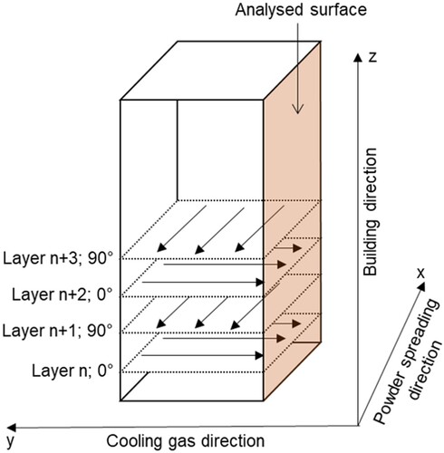
To avoid the influence of process gas cooling in the sample width direction, the surface side impacted by the gas was selected for subsequent analysis (see ). The samples were metallographically ground and polished. Cross-sections images were captured with an optical microscope image device (OM, Wild Heerbrugg M420 ZOOM) at the centre in Z-direction of the polished as-printed samples. The porosity fraction expressed as percentage of the area (approx. 4.5 mm × 9.5 mm), as well as the pore shapes, were quantified using the freely available software ImageJ.
Figure 1. Coordinate system used for sample fabrication, indicating surface area used for corresponding analysis.
2.4. Microstructure analysis
Subsequently, cross-sections of the samples were analysed with scanning electron microscopy (SEM; Zeiss Sigma 500 with a Gemini-type field emission gun in BSE mode). Backscattered Electrons mode (BSE) was used to obtain especially high-resolution images with high contrast. Phase identification was performed with the electron backscatter diffraction analysis (EBSD; EDAX detector and TSL OIM 7.2 software) in SEM JEOL JSM 6500F. Additionally, a coupled energy-dispersive X-ray analysis (EDS) detector was employed for chemical composition analysis. Selected samples were characterised using transmission electron microscopy (TEM; JEOL JEM-2110Plus) operated at 200 kV on samples prepared with a focussed ion beam system (FIB; FEI Helios G4 CX) operated at 30 kV). X-ray diffraction (XRD, D8 advance A25-X1 Bruker) with a Co-Kα radiation and step size of 0.009° was used for generating diffraction patterns, sequentially evaluated with Rietveld refinement using the X’Pert HighScore software (Malvern Panalytical) for comprehensive phase identification. For detailed examination at the atomic scale, atom probe measurements were performed on a LEAP 5108 HR for elemental identification and accurate quantification of Fe, Ti, and B components.
2.5. Mechanical characterisation
Vickers hardness measurements were performed on a NEMESIS 5100 hardness testing system in automatic mode, using a test load of HV1 for area measurements. For nanoindentation analysis, a TriboIndenter from Hysitron equipped with a Tip North star cube corner Ti 051 indenter was used. A total of 400 data points was recorded, measured with a test load of 300 µN and a load function of 0.5 s (loading) – 0.5 s (holding).
3. Results
3.1. Online pyrometry
shows the average pyrometer signals of each layer on the printed surface at three substrate temperatures. At 400 and 600 °C, similar pyrometer signals are measured, indicating comparable melt pool temperatures. However, when the substrate temperature is increased from 600 to 800 °C, the pyrometer signal significantly rises by approximately 22%. This can be explained by the substrate being preheated above the Curie point of Fe (770 °C), before which the specific heat reached a pronounced maximum. At lower substrate temperatures, a significant fraction of the laser energy was required to surpass this specific heat peak. In contrast, heating the substrate to 800 °C results in a much greater impact of laser energy on the melt pool temperature. ()
Figure 2. Pyrometer signal during PBF-LB/M at similar layers manufactured with different substrate preheating (Ts: 400, 600, and 800 °C).
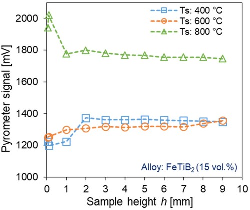
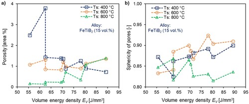
Figure 3. Impact of volume energy density EV on; (a) porosity (area %) and (b) sphericity of pores.
3.2. Porosity and defect analysis
The resulting volume energy density as a function of laser power and scan velocity are presented in .
Table 3. Process parameters (laser powder and scan speed) and resulting volume energy densities of the PBF-LB/M formed samples.
shows the results of porosity (excluding cracks) and average pore sphericity at the three different substrate temperatures with varying volume energy density. At substrate temperatures of 400 and 600 °C, porosity levels range between approx. 1% and 1.5% for the majority of the volume energy density values (with exceptions at 400 °C exceeding 2 area-%). A substrate temperature of 800 °C results in significantly lower porosity levels ranging between 0.16% and 0.28% for volume energy densities between 55 and 70 J/mm3. However, a further increase of volume energy to 90 J/mm3density leads to an increase of porosity of 1.38%, surpassing that obtained at a TS = 400 °C.
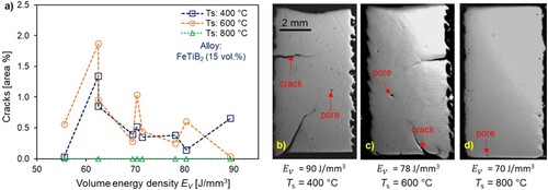
Figure 4. (a) Relationship between crack area (%) and volume energy density. PBF-LB/M samples at different substrate temperatures; (b) Ts = 400 °C, (c) Ts = 600 °C, and (d) Ts = 800 °C.
These results are consistent with the melt pool temperatures measured with pyrometry: when the substrate is preheated above Curie temperature, minimal heat is needed to obtain full melting. However, if this heat flow is further increased, unstable keyhole configurations may result, leading to increased porosity.
As seen in , cracks occurred for lower substrate temperatures (Ts = 400 and 600 °C) regardless of Ev values, suggesting the impact of the thermal gradient on residual stress accumulation within the material. The cracks originated primarily from the bottom and side edge of the samples. Along with those, smaller cracks are found within the samples. Cracking (area %) tendentially decreases with increasing volume energy density ((a)). For 800 °C preheating, mostly crack-free samples were produced within the selected parameter window, revealing the positive influence of increasing the substrate temperature on sample fabrication. As evidenced by the representative optical micrographs displayed in (b–d), the formation of large cracking along the sample was entirely prevented by increasing the substrate preheating temperature. Hence, the lack of cracking quantified when employing of TS = 800 °C demonstrate the advantages of this approach.
Regarding pore morphology, the pores exhibit mostly spherical shapes (sphericity ranging from 0.8 to 0.95) for all substrate preheating temperatures ((b)), indicating consistent morphological characteristics independent of the substrate temperatures.
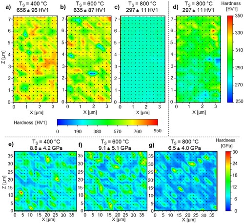
(a–c) shows the results of hardness measurements of the as-printed samples with lowest porosity at the three different substrate temperatures. The average hardness values for TS = 400 °C and TS = 600 °C fall within a similar range, measuring 656 ± 96 HV1 and 635 ± 87 HV1, respectively. At TS = 800 °C, however, a significantly decreased hardness of 297 ± 11 HV1 was measured, accompanied by a notably decreased standard deviation. In (a and b), a slight reduction of the hardness with higher specimen height and at the right side of the specimen is observed. In order to visualise the spatial hardness distribution for the sample with a substrate temperature of TS = 800 °C, the color-scale is adapted in (d). The result demonstrates a more uniform hardness distribution compared to lower substrate preheating temperatures (TS = 400 °C and TS = 600 °C). In addition, localised differences can also be identified on the right side of the specimen. In (e–g), the nanoindentation results show that the ground level at lower substrate temperatures is higher than at TS = 800 °C. In particular, it can be seen that at TS = 800 °C, the higher hardness values are more tightly localised.
Figure 5. Hardness (a–d) and nanohardness (e–g) of the as-printed samples with lowest porosity at different substrate temperatures.
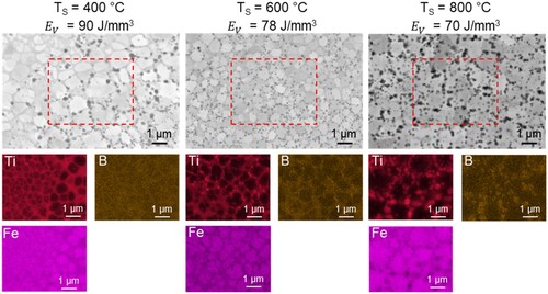
shows the SEM images and the results of the EDS measurement. A fine nanometric scale microstructure consisting of three constituents at TS = 400 °C and TS = 600 °C is observed. At TS = 800 °C, only the components ferritic matrix and precipitates are visible. The different areas consist of (i) a granular matrix, (ii) a second phase between the matrix grains, as well as (iii) small particles of a darker contrast. These inhomogeneous distributed dark particles with an approximate size of 50–70 nm at 400 and 600 °C and an approximate size of 200–300 nm at TS = 800 °C could be determined as TiB2 borides in a previous work [Citation33]. EDS revealed that the phase between the Fe-containing islands consists of Fe and Ti.
Figure 6. SEM BSE and EDS characterisation of printed Fe-TiB2 samples at (a) Ts = 400 °C, (b) Ts = 600 °C and, (c) Ts = 800 °C.
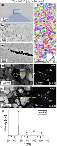
(a and b) display representative SEM micrographs of the obtained microstructure and crack progression for TS = 400 °C, revealing an inhomogeneous microstructure. The EBSD measurement ((c)) suggests that the matrix consists of α-Fe with an average grain diameter of 0.54 ± 0.14 µm. A closer examination of the cracks ((d)) reveals their initiation and propagation between the insular ferritic matrix. Together with the corresponding EDS results, these findings suggest a second phase consisting of brittle intermetallic compounds. TEM analyses ((d and e)) further confirm the existence of the α-Fe and a second phase between the ferritic grains. Due to previous publications in which the TiB2 phase was characterised in detail, it was not investigated by TEM [Citation33]. The diffraction patterns of the second phase analysis indicate similarity with Fe3B. The diffraction patterns of the intergranular area are absent from the TiB2 compound. Subsequent XRD measurement () yielded a result consistent with the TEM analysis, in which the distinct crystalline peaks were assigned to α-Fe [Citation35]. Notably, neither TiB2 nor any other compound could be successfully identified.
Figure 7. High resolution microstructure characterisation of the printed Fe-TiB2 samples at Ts = 400 °C, SEM BEC micrograph (a,b) SEM image, (c) EBSD map, (d) SEM image of Crack initialisation (e,f) and corresponding TEM analysis with SAD patterns and (g) XRD graph.
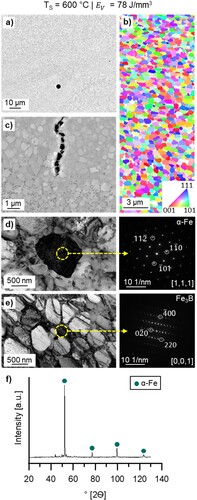
summarises the results of high-resolution microstructure characterisation for TS = 600 °C. The SEM images ((a)) reveal a fine nanometric scale microstructure with finely distributed TiB2 borides, similar to observations at 400 °C. The borides are distributed inhomogeneously in the sample. In addition to the island-shaped ferritic matrix and the TiB2 particles, a third phase consisting of B, Fe and Ti is also observed, identified as Fe3B by Rietveld analysis. These characterisation methods were unable to detect any significant difference in microstructure composition and the sizes of the phases with regard to substrate temperatures 400 and 600 °C. The crack progression ((c)) showed a similar pattern to the one observed at a substrate temperature of TS = 400 °C.
Figure 8. High resolution microstructure characterisation of the printed Fe-TiB2 samples at Ts = 600 °C, SEM BEC micrograph (a,b) SEM image, (c) EBSD map, (d,e) corresponding TEM analysis with SAD patterns and (f) XRD graph.
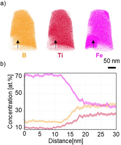
For further investigation of the unknown phase and gain a deeper understanding of the local chemical composition, atom probe tomography was performed between the ferritic matrix (). Results indicate local chemical differences within the matrix ((a)). A measurement within the marked region showed that this phase consists of equal amounts of Fe and B, with a smaller percentage of Ti ((b)).
Figure 9. Atom probe measurement of the printed Fe-TiB2 samples at Ts = 600 °C, (a) measured atom probe tip with marked area for detailed measurement, (b) chemical composition in at.% of the marked area.
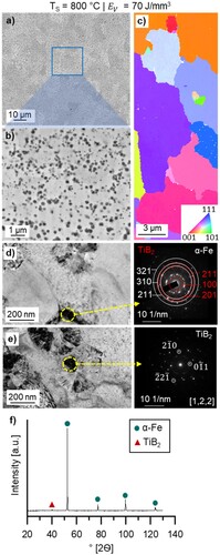
An increase in the substrate temperature from TS = 600 to TS = 800 °C is associated with a significant change in the microstructure ((a, b)). The microstructure exhibits a clear coarsening of the grains and particles. Specifically, the ferritic matrix undergoes coarsening, with grain sizes reaching several micrometres and displaying an irregular shape. Additionally, the particle size increases to about 200–300 nm (c). Unlike the lower substrate temperatures TS = 400 °C and TS = 600 °C, no additional intergranular constituent is present between the ferritic grains. TEM analysis reveals the presence of TiB2 in addition to α-Fe, attributed to its increased size. Furthermore, α-Fe was identified as the primary matrix alongside TiB2. These findings are further confirmed through XRD measurement, which exhibits characteristic peaks corresponding to α-Fe and TiB2, thus corroborating the TEM results.
Figure 10. High resolution microstructure characterisation of the printed Fe-TiB2 samples at Ts = 800 °C, SEM BEC micrograph (a,b) SEM image, (c) EBSD map, (d,e) corresponding TEM analysis with SAD patterns and (f) XRD graph.
4. Discussion
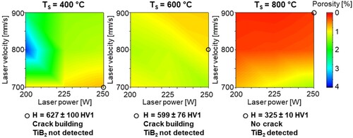
The results of the present study clearly demonstrate that both the volume energy density (laser parameter) and the substrate temperature directly influence the porosity of HMS processed by PBF-LB/M (). For the constant laser parameters, the samples manufactured on a substrate heated to 400 °C contained 1–3.5% higher porosity than the samples with 800 °C substrate temperature, which is consistent with the measured surface temperature level (). Lower preheating temperatures lead to increased temperature gradients and resultingly to cracks, as shown in . In contrast, almost crack-free samples could be produced with TS = 800 °C, achieving a density of approximately 99.8%. The results suggest the favourable influence of elevating the substrate temperature on the production of high-quality, densely consolidated parts via PBF-LB/M.
: summarises the process window overview employed in this study. It is observed that achieving high material density necessitates higher laser powers and appropriate laser velocities, particularly at lower substrate preheating temperatures, as otherwise high porosity occurs. Nevertheless, crack formation within the investigated parameters was inevitable up to a substrate preheating temperature of 600 °C. Therefore, conducting further investigations within the temperature range of TS = 600 °C to 800 °C would contribute to identifying a suitable process window for crack-free HMS. However, it is important to note that achieving substrate preheating of 600 °C and above during the PBF-LB/M process presents challenges for more complex geometries.
Figure 11. Investigated PBF-LB/M process window for Fe-TiB2 at different substrate temperatures, further investigated samples marked.
The micro-hardness measurements reveal similar results with higher and inhomogeneous hardness distributions observed at TS = 400 and 600 °C, attributed to the higher cooling rates. These local hardness variations can be associated with pronounced thermal fluctuation due to lower surface temperatures and resultingly higher local cooling rates. Consequently, this spatial distribution of cooling rates leads to distinct microstructures and hardness.
In contrast, at TS = 800 °C, thermal fluctuations become smaller, promoting a more homogeneous microstructure and a uniform hardness distribution. Besides, the resulting hardness of 325 ± 10 HV1 is substantially higher than that of spray-formed material (about 250 HV1) of identical composition [Citation8]. This compares well to the PBF-LB/M materials post-heat treated at 1000°C (about 358 HV1 [Citation33]), but without the extra effort of heat treatment.
Microstructures with similar matrix and particle size, but without preheating [Citation33], were observed at TS = 400 and 600 °C. Although not revealed by XRD, due to particle size being below the measurement range, TiB2 could be detected by SEM. The second phase in these microstructures appears to be a metastable boride, Fe3B, similarly found in a Fe-B alloy produced through rapid solidification [Citation36] and possessing a similar B content. The resulting increase in hardness can be attributed to the presence of such metastable Fe3B, which exhibits a hardness of 9.1 GPa [Citation37], surpassing the measured values in this study. However, the small size and impure form of the Fe3B phase pose challenges for individual measurement. In addition, the identification is further complicated by the elevated Ti content within this phase. Other possible phases, including Ti, TiC, Me23C6, TiFe2 and Ti2Fe have already been excluded based onprevious research [Citation33] that provided a more detailed investigation of this phase in a similar material system. The resulting metastable intermediate phase is caused by the rapid solidification in the PBF-LB/M process. The rapid solidification prevents the formation of the equilibrium phase TiB2, causing the fraction of the TiB2 phase to decrease with increasing cooling rate and favours the formation of the metastable intermediate phase.
Investigation of the crack profiles at the substrate temperatures TS = 400 °C and TS = 600 °C reveals that cracks initiate in the second phase and only cross the ferritic grains during the cracking process. This observation, along with the higher hardness compared to the sample with a substrate temperature of TS = 800 °C and the larger areas of increased hardness values within the nanoindentation, shows that the intermetallic Fe3B phase exhibits an enhanced hardness compared to the ferritic matrix. Another potential factor contributing to increased hardness at lower substrate temperatures can be attributed to the grain size. Here, the substantial difference in grain size between the lower substrate temperatures and the 800 °C suggests grain refinement. In contrast, a distinct microstructure is observed at TS = 800 °C, which can be attributed to the higher temperature level and the occurrence of a phase transformation between 600 °C and 800 °C. At TS = 800 °C, both the grains and particles exhibit significant enlargement due to coarsening at a slower cooling rate, resulting in punctate hardness increases detectable within nanoindentation. This softer yet more ductile matrix inherent to the coarser microstructure, coupled with the absence of the Fe3B phase, positively contributes to reducing crack formation.
It has been demonstrated in previous work [Citation33] that the TiB2 phase can be formed in the matrix through subsequent heat treatment. In this context, annealing of the printed layer using a secondary laser with reduced energy levels may introduce coarsening and in-situ formation of the TiB2. Additional alloying elements, e.g. Mn, may further enhance the material properties and suppress the second phase. The identified process window for FeTiB2 can serve as valuable guideline for other alloys, such as those containing 12 vol.% and 20 vol.%.
5. Conclusion
The present work describes a systemic study of the PBF-LB/M process parameters and subsequent microstructure analyses of Fe-TiB2 high modulus steels. Substrate temperatures from 400 °C to 800 °C were investigated in an attempt to avoid crack formation in the matrix. An PBF-LB/M process window for denser and crack-free HMS has been identified, positively contributing to producing more complex geometries.
The following key conclusions can be drawn from this study:
Crack-free samples with a density of about 99.8% can be successfully achieved with substrate preheating of 800 °C. At temperatures of 400 and 600 °C, crack formation and propagation occurred, requiring higher laser energies to manufacture comparably dense specimens.
Analysis of the melting surface temperatures revealed almost identical signals at 400 and 600 °C, while a notable increase of approx. 22% higher was observed at 800 °C substrate preheating temperature. This observation may be associated with the laser’s absorptivity characteristics on the surface at higher pre-heating temperatures.
Inhomogeneously distributed high hardness values were measured in the PBF-LB/M samples manufactured with 400 and 600 °C preheating temperatures. In contrast, softer and more homogeneous materials have been produced at 800 °C.
Due to faster cooling rates, comparable microstructures and grain sizes were formed at 400 and 600 °C substrate preheating temperatures. Further investigations are required to ensure that the second phase is Fe3B. At 800 °C, TiB2 has been distinctly detected in the Fe-matrix, in which the microstructure is comparable with spray-formed materials.
In conclusion, this study highlights the potential of the PBF-LB/M process for producing crack-free high-modulus steels. The identified process window enables the fabrication of denser and more complex geometries. To further enhance mechanical properties, future research should focus on confirming the nature of the second phase and exploring the optimisation of process parameters and alloying elements. By incorporating these findings into practical applications, additive manufacturing capabilities will be significantly elevated across in various industries.
Disclosure statement
No potential conflict of interest was reported by the author(s).
Additional information
Funding
References
- Tanaka K, Saito T. Phase equilibria in TiB2-reinforced high modulus steel. J Phase Equilibria. 1999;20(3):207–214. doi: 10.1361/105497199770335730
- Kulikowski Z, Godfrey TMT, Wisbey A, et al. Mechanical and microstructural behaviour of a particulate reinforced steel for structural applications. Mater Sci Technol. 2000;16(11–12):1453–1464. doi: 10.1179/026708300101507451
- Zhang H, Springer H, Aparicio-Fernández R, et al. Improving the mechanical properties of Fe – TiB2 high modulus steels through controlled solidification processes. Acta Mater. 2016;118:187–195. doi: 10.1016/j.actamat.2016.07.056
- Springer H, Baron C. High-modulus steels. In: Rana R, editor. High-performance Ferrous Alloys. Cham: Springer International Publishing; 2021. p. 291–326.
- Tjong SC, Ma ZY. Microstructural and mechanical characteristics of in situ metal matrix composites. Mater Sci Eng: R Rep. 2000;29(3):49–113. doi: 10.1016/S0927-796X(00)00024-3
- Li B, Xu K, Chen R, et al. On the fatigue crack propagation mechanism of a TiB2-reinforced high-modulus steel. Compos Part B: Eng. 2020;190:107960. doi: 10.1016/j.compositesb.2020.107960
- Springer H, Fernandez RA, Duarte MJ, et al. Microstructure refinement for high modulus in-situ metal matrix composite steels via controlled solidification of the system Fe–TiB2. Acta Mater. 2015;96:47–56. doi: 10.1016/j.actamat.2015.06.017
- Springer H, Baron C, Szczepaniak A, et al. Stiff, light, strong and ductile: nano-structured high modulus steel. Sci Rep. 2017;7(1):2757. doi: 10.1038/s41598-017-02861-3
- Hussain S, Cui C, Temple N, et al. Porosity and microstructure of steel tubes spray-formed by close-coupled atomizer. J Mater Process Technol. 2020;276:116407. doi: 10.1016/j.jmatprotec.2019.116407
- Gu DD, Meiners W, Wissenbach K, et al. Laser additive manufacturing of metallic components: materials, processes and mechanisms. Int Mater Rev. 2012;57(3):133–164. doi: 10.1179/1743280411Y.0000000014
- Frazier WE. Metal additive manufacturing: a review. J Mater Eng Perform. 2014;23(6):1917–1928. doi: 10.1007/s11665-014-0958-z
- AlMangour B, Kim Y-K, Grzesiak D, et al. Novel TiB2-reinforced 316L stainless steel nanocomposites with excellent room- and high-temperature yield strength developed by additive manufacturing. Compos Part B: Eng. 2019;156:51–63. doi: 10.1016/j.compositesb.2018.07.050
- Kasperovich G, Haubrich J, Gussone J, et al. Correlation between porosity and processing parameters in TiAl6V4 produced by selective laser melting. Mater Des. 2016;105:160–170. doi: 10.1016/j.matdes.2016.05.070
- Lewandowski JJ, Seifi M. Metal additive manufacturing: a review of mechanical properties. Annu Rev Mater Res. 2016;46(1):151–186. doi: 10.1146/annurev-matsci-070115-032024
- Tang M, Pistorius PC, Beuth JL. Prediction of lack-of-fusion porosity for powder bed fusion. Addit Man. 2017;14:39–48. doi: 10.1016/j.addma.2016.12.001
- Ramirez-Cedillo E, Sandoval-Robles JA, Ruiz-Huerta L, et al. Process planning guidelines in selective laser melting for the manufacturing of stainless steel parts. Procedia Man. 2018;26:973–982. doi: 10.1016/j.promfg.2018.07.125
- Yusuf SM, Gao N. Influence of energy density on metallurgy and properties in metal additive manufacturing. Mater Sci Technol. 2017;33(11):1269–1289. doi: 10.1080/02670836.2017.1289444
- Bertoli US, Wolfer AJ, Matthews MJ, et al. On the limitations of volumetric energy density as a design parameter for selective laser melting. Mater Des. 2017;113:331–340. doi: 10.1016/j.matdes.2016.10.037
- Prashanth KG, Scudino S, Maity T, et al. Is the energy density a reliable parameter for materials synthesis by selective laser melting? Mat Res Lett. 2017;5(6):386–390. doi: 10.1080/21663831.2017.1299808
- Carter LN, Wang X, Read N, et al. Process optimisation of selective laser melting using energy density model for nickel based superalloys. Mater Sci Technol. 2016;32(7):657–661. doi: 10.1179/1743284715Y.0000000108
- Kuo C, Chua CK, Peng P, et al. Microstructure evolution and mechanical property response via 3D printing parameter development of Al–Sc alloy. Virtual Phys Prototyp. 2020;15(1):120–129. doi: 10.1080/17452759.2019.1698967
- Savinov R, Shi J. Microstructure, mechanical properties, and corrosion performance of additively manufactured CoCrFeMnNi high-entropy alloy before and after heat treatment. Mat Sci Addit Man. 2023;2(1):42. doi: 10.36922/msam.42
- Yu WH, Sing SL, Chua CK, et al. Influence of re-melting on surface roughness and porosity of AlSi10Mg parts fabricated by selective laser melting. J Alloy Compd. 2019;792:574–581. doi: 10.1016/j.jallcom.2019.04.017
- Yu W, Xiao Z, Zhang X, et al. Processing and characterization of crack-free 7075 aluminum alloys with elemental Zr modification by laser powder bed fusion. Mat Sci Addit Man. 2022;1(1):4. doi: 10.18063/msam.v1i1.4
- Zhang X, Xiao Z, Yu W, et al. Influence of erbium addition on the defects of selective laser-melted 7075 aluminium alloy. Virtual Phys Prototyp. 2022;17(2):406–418. doi: 10.1080/17452759.2021.1990358
- Mao YW, Yuan JM, Heng YH, et al. Effect of hot isostatic pressing treatment on porosity reduction and mechanical properties enhancement of 316L stainless steel fabricated by binder jetting. Virtual Phys Prototyp. 2023;18(1):e2174703. doi: 10.1080/17452759.2023.2174703
- Dadbakhsh S, Mertens R, Hao L, et al. Selective laser melting to manufacture “in situ” metal matrix composites: a review. Adv Eng Mater. 2019;21(3):1801244. doi: 10.1002/adem.201801244
- Dai D, Gu D. Tailoring surface quality through mass and momentum transfer modeling using a volume of fluid method in selective laser melting of TiC/AlSi10Mg powder. Int J Mach Tools Manuf. 2015;88:95–107. doi: 10.1016/j.ijmachtools.2014.09.010
- Yuan P, Gu D, Dai D. Particulate migration behavior and its mechanism during selective laser melting of TiC reinforced Al matrix nanocomposites. Mater Des. 2015;82:46–55. doi: 10.1016/j.matdes.2015.05.041
- Springer H, Baron C, Mostaghimi F, et al. Additive manufacturing of high modulus steels: new possibilities for lightweight design. Addit Man. 2020;32:101033. doi: 10.1016/j.addma.2019.101033
- Ciftci N, Ellendt N, Barreto ES, et al. Increasing the amorphous yield of {(Fe 0.6 Co 0.4 ) 0.75 B 0.2 Si 0.05 } 96 Nb 4 powders by hot gas atomization. Adv Powder Technol. 2018;29(2):380–385. doi: 10.1016/j.apt.2017.11.025
- Hussain S, Buss L, Yao D, et al. Droplet velocity and thermal state from hot gas atomization of steel melt: impact on the quality of the spray-formed tubular deposit. Adv Powder Technol. 2022;33(7):103640. doi: 10.1016/j.apt.2022.103640
- Springer H, Baron C, Mostaghimi F, et al. Additive manufacturing of high modulus steels: new possibilities for lightweight design. Addit Man. 2020;32:101033. doi: 10.1016/j.addma.2019.101033
- Gärtner E, Witte A, Peter NJ, et al. Melt pool signatures of TiN nanoparticle dry-coated Co25Cr25Fe25Ni25 metal powder in laser-powder-bed-fusion. Mater Des. 2023;226:111626. doi: 10.1016/j.matdes.2023.111626
- Pelz A. Microstructure and properties of new developed Fe-Cr-C-B powders for wear-protection purposes. ITSC2009. 2009:849–854.
- Jiménez JA, Adeva P, Cristina MC, et al. Characterization of rapidly solidified ultrahigh boron steels. Mater Sci Eng A. 1992;159(1):103–109. doi: 10.1016/0921-5093(92)90403-N
- Li L-H, Wang W-L, Hu L, et al. First-principle calculations of structural, elastic and thermodynamic properties of Fe–B compounds. Intermetallics. 2014;46:211–221. doi: 10.1016/j.intermet.2013.11.007