
 ?Mathematical formulae have been encoded as MathML and are displayed in this HTML version using MathJax in order to improve their display. Uncheck the box to turn MathJax off. This feature requires Javascript. Click on a formula to zoom.
ABSTRACT
Novel ultralight meta-sandwich structures inspired by Kirigami (MSS) are proposed in this study. The topological designs of uniform (MSS-U) and non-uniform (MSS-N) sizes are studied based on the inconsistent distribution of the biomaterials. First, MSS-U and MSS-N are manufactured using laser powder bed fusion (LPBF) technology, and energy absorption prediction formulas are successfully derived by extracting the experimental deformation features. It is found that MSS-N exhibits a higher energy absorption level than MSS-U. Compared to the conventional corrugated sandwich structures (CSS), the MSS achieves better crashworthiness indicators and more folding numbers. Moreover, the parameter effect of the MSS is analysed, and the minimum/maximum thickness and folding angle significantly influence the crashworthiness responses. The mechanical properties of MSS-N can be regulated by changing the folding angle while maintaining the same thickness. The MSS proposed in this study can achieve a higher energy absorption efficiency at the same density compared to other existing mechanical structures. Interestingly, the feasibility of applying MSS to automobiles and plant protection drones is verified by changing the materials and macro-configurations. The design concept presented in this study provides a promising method for obtaining sandwich structures with excellent cushioning properties for engineering protective equipment.
1. Introduction
High-efficiency cushioning characteristics are crucial design requirements for protective engineering equipment [Citation1–Citation3]. Innovative cushioning structures have been developed owing to the increasing demand for mechanical protection. In recent years, meta-sandwich structures have attracted significant attention in advanced engineering equipment due to their ultralight and high load-bearing mechanical properties, and they have been successfully applied in transportation engineering fields such as rail transport [Citation4–Citation6], automobiles [Citation7–Citation10], aerospace [Citation11–Citation13], and ships [Citation14–Citation16]. A series of meta-sandwich schemes with different configurations and material matching was proposed to ensure the cushioning performance of mechanical equipment under load conditions.
With the gradual development of foaming technologies, ultralight foam materials are often used in the design of meta-sandwich structures. For example, Zhou et al. [Citation17] developed polyvinyl chloride foam meta-sandwich structures and examined their mechanical responses at different impact angles and speeds. It was determined that the energy absorption of the polyvinyl chloride foam effectively cushions the impact of hail, thus protecting the rear panel of the sandwich structures. Sun et al. [Citation18] analysed the impact location, foam strength, and panel thickness on the dynamic response of meta-sandwich structures using theoretical models. It was determined that the impact force decreases with an increase in the distance of the impact position from the midspan, and it increases with an increase in foam strength and panel thickness. Additionally, Khaire et al. [Citation19] examined the antiknock performance of meta-sandwich panels with gradient foam cores under explosive load. The graded foam core can improve the anti-knock performance when compared to a single-layer foam board with uniform density. Foam sandwich materials produced by the foaming process exhibit excellent mechanical potential. However, it is difficult to ensure that foam materials have customisable properties.
Additionally, ultralight honeycomb materials are favoured in the engineering field, providing inspiration for meta-sandwich design. For example, Lin et al. [Citation20] proposed a method to improve energy absorption capacity by filling a honeycomb core with a shear-thickening gel mixed with silica particles. The load curves and damage modes indicate that the proposed honeycomb sandwich structure can effectively reduce the penetration depth and impact damage. Related studies have shown that the impact resistance of honeycomb sandwich structures can be improved by optimising the upper and lower panels. Morozov et al. [Citation21] replaced the upper and lower panels of metal meta-sandwich structures with carbon fibres and conducted experimental studies on the impact response of carbon fibre honeycomb sandwich structures using drop impact tests. Different failure modes, such as delamination, matrix cracking, and fibre fracture, were observed. Zhang et al. [Citation22] developed multilayer aluminium honeycomb meta-sandwich structures and examined their dynamic response under low-speed impact. The influences of the diameter gradient of the upper and lower honeycomb-inscribed circles, core thickness gradient, and core thickness on the bearing capacity and energy absorption of the meta-sandwich structure are discussed. It was found that designing a certain range of curvature angles and panel thicknesses can effectively improve energy absorption and damping capabilities. Overall, it can be concluded that the composite meta-sandwich structure designed with foam and honeycomb cores is mainly devoted to exploring its drop weight penetration and bending behaviours. However, the working conditions of sandwich structures may be diverse.
Novel meta-sandwich structures have been proposed to satisfy different impact engineering protection requirements. Fleck et al. [Citation23] analysed the dynamic mechanical response of stainless-steel meta-sandwich structures with Y-shaped frame cores and found that the force transmitted from the Y-shaped frame core to the back is significantly smaller than that of traditional corrugated core bodies, which has a better impact protection performance. Cheng et al. [Citation24] proposed a U-shaped corrugated meta-sandwich structure for applications in future ship and ocean engineering structures. Owing to the large number of core cells involved in the deformation and energy absorption in the U-shaped corrugated meta-sandwich structure, its lateral impact resistance performance was significantly better than its longitudinal performance. Liu et al. [Citation25] proposed a design scheme for an X-shaped frame meta-sandwich structure and conducted perforation tests. By examining the low-speed impact behaviour of an X-shaped frame meta-sandwich structure, it was determined that the impact response and resulting damage state were closely related to the impact energy and impact location. Overall, excellent mechanical properties were realised by developing meta-sandwich design schemes with different topological configurations. These meta-sandwich structures can be processed using extrusion technology or mechanical moulding. Despite their high manufacturing availability, they can only be used for two-dimensional cross-sectional configurations, which limits the design space for the mechanical improvement of meta-sandwich structures.
Novel design ideas were proposed to obtain ultralight meta-sandwich structures with high energy absorption. For example, Yang et al. [Citation26] proposed a new lightweight biomimetic double sine wave (DSC) meta-sandwich structure to improve impact resistance. Compared with the equilateral triangle- and sine-wave sandwich panels, the bionic DSC sandwich panel significantly improved the crashworthiness of the structure and reduced the initial peak force. Xu et al. [Citation27] proposed a novel bio-inspired meta-sandwich structure with sinusoidal cores, based on the dactyl club microstructure of Odontodactylus scyllarus, and conducted multi-criteria optimisation to find structural parameters with excellent crashworthiness. In recent years, flexible and adjustable Kirigami element design methods have attracted attention and have been applied to the design of meta-sandwich structures. For example, Li et al. [Citation28] proposed a novel origami honeycomb meta-sandwich structure and examined the influence of the low-speed impact response. Origami-inspired honeycomb structures have been found to outperform traditional honeycomb panels in terms of their energy-absorption characteristics. Lu et al. [Citation29] manufactured rectangular metal meta-sandwich structures with aluminium origami cores and conducted a loading analysis on flat-end, hemispherical, and conical indenters. The effects of the wall thickness, edge length, and number of origami cores on the ballistic performance were observed and analysed. Most of the aforementioned research focused on the resistance to perforation performance of meta-sandwich structures inspired by origami, but there is relatively a paucity of analysis on the mechanical response under flat-plate crushing conditions.
Recently, the development of additive manufacturing technology has provided effective ideas for the fabrication of ultralight mechanical structures with complex configurations, providing opportunities for the further development of meta-sandwich structures [Citation30–Citation34]. Therefore, this study developed a design route for a novel sandwich core using Kirigami elements and proposed an ultralight meta-sandwich structure inspired by Kirigami (MSS). Meta-sandwich structures inspired by Kirigami with uniform (MSS-U) and non-uniform thicknesses (MSS-N) were designed and analysed. The main conclusions of this study are as follows: Section 2 describes the geometric configuration and fabrication of the MSS. Section 3 presents the experiment and numerical simulation. Section 4 presents the results of the analysis and discussion. The application scenarios are discussed in Section 5. Finally, the major conclusions are presented in Section 6.
2. Design and fabrication
2.1. Meta-sandwich structures
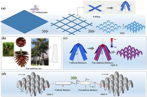
Recently, Kirigami elements have been widely used in mechanical engineering because of their highly adjustable characteristics. In this study, novel meta-sandwich structures inspired by Kirigami (MSS) are proposed, which are formed by folding at a certain angle based on paper cutting, as shown in (a). According to this design concept, on the premise of determining the design size of paper-cutting, the configuration of meta-sandwich structures can be easily changed by continuously regulating the folding angle . Specifically,
and
denote the length and width of the folded structure, respectively. Additionally, owing to the particularity of non-uniform variable sizes, non-uniform sizes have been found in many natural biological materials, such as pine cones and tropical trees, as shown in (b). It is not difficult to understand that arranging materials in appropriate positions is a design strategy that maximises their effectiveness. Furthermore, the sandwich meta-structure inspired by Kirigami with non-uniform thickness is also designed, and the non-uniform thickness is linearly distributed horizontally on the sandwich wall, as shown in (c). Finally, the meta-sandwich structures inspired by Kirigami with uniform (MSS-U) and non-uniform thicknesses (MSS-N) are shown in (d). MSS-N has the minimum thickness at the end of the wall in the horizontal direction and the maximum thickness at the middle position. The linear variation between the maximum and minimum thicknesses can be expressed by the following relationship:
(1)
(1) where
denotes the thickness at distance
and
is the average thickness.
Figure 1. Meta-sandwich structures inspired by Kirigami with uniform (MSS-U) and non-uniform thicknesses (MSS-N): (a) Schematic diagram of Kirigami-inspired structures; (b) Natural biological materials; (c) Non-uniform thickness design of MSS-N; (d) MSS-U and MSS-N.
To quickly fabricate the specimens, MSS-U and MSS-N were manufactured via laser powder bed fusion (LPBF) technology using a LIM-X260A machine (Tianjin LiM Laser Technology Co., Ltd, China). The main manufacturing steps of LPBF are shown in . First, the 3D model file was transferred to the printing device LIM-X260A, and the laser was used as an energy source to scan the metal powder bed layer by layer in a planned path in a 3D CAD slice model. The scanned metal powder was melted and solidified to obtain the initial sample. Then, a vacuum furnace was used to perform solid solution heat treatment on the test specimen to improve the mechanical properties of the prepared material. Further geometric processing was performed on the specimens via shot peening and mechanical processing to ensure that the prepared specimens satisfied the design requirements to the maximum possible extent. After repeated adjustment and calibration, the processing parameters adopted are as follows: laser power of 285 W, laser beam diameter of 0.085 mm, layer thickness of 40 μm, and scanning speed of 950 mm/s.
Figure 2. Additive manufacturing of MSS: (a) Additive manufacturing process; (b) Stress-strain curves; (c) MSS-U and MSS-N specimens.
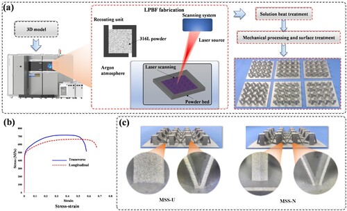
The fabrication process of MSS uses 316L stainless steel as the powder material. The mean diameter of powder size is 34 μm. The proportion of powder particles below 22.41, 32.68, and 48.06 μm is 10%, 50%, and 90%, respectively. The basic mechanical properties are as follows: material density of 7.86 g/cm3, Poisson's ratio of 0.3, elastic modulus of 186 GPa, and yield stress of 448 MPa. The stress–strain curves of 316L stainless steel are shown in . Finally, MSS-U (wall thickness of 0.75 mm) and MSS-N (maximum thickness of 1 mm and minimum thickness of 0.5 mm) were fabricated. The length and width
of the folding structure are 15 and 5 mm, respectively. To further demonstrate the quality of the metal printing moulding process, microscopic observations of the formed MSS were conducted. The edges of MSS-U and MSS-N are slightly rough, with small and unsmooth materials distributed on the wall. Despite some manufacturing uncertainties that caused defects, the overall printing quality of the MSS specimens is satisfactory.
2.2. Crashworthiness criteria
To study the crashworthiness performance of the MSS, several general crashworthiness criteria were defined.
Specific energy absorption ():
represents the energy absorbed per unit mass, which is a key indicator for determining the absorption capability and is expressed as.
(2)
(2) where
denotes the transient crushing force at displacement
, and
denotes the total weight of the structure.
denotes the effective crushing displacement in the load direction and its value primarily refers to the displacement corresponding to the structure before compaction.
Initial peak crushing force ():
is the maximum crushing force during the initial loading stage.
Crush force efficiency ():
is the criterion used to characterise the load consistency and is expressed as follows:
(3)
(3) where
denotes the maximum crushing force during the global loading stage.
A consensus has been reached that a higher implies better energy absorption potential and a higher
indicates good consistency in the load during the crushing process. However, a high
can cause severe acceleration during the initial loading stage, and the initial load should be limited to the maximum possible extent.
3. Experiment and simulation details
3.1. Experiment description
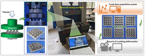
To analyse the mechanical properties of the MSS, the specimens were placed on a universal testing machine for the compression test. As shown in , the specimen is placed between the upper and lower platforms during the crushing tests. The load was generated by moving the upper platform at a constant velocity (2 mm/min) until the compressive displacement reached 11.4 mm. A total of 6 specimens from MSS-N and MSS-U were tested. The crushing responses were collected using the SANS data system, and the deformation process was recorded using an industrial digital camera (SUA134GC).
Figure 3. Experiment progress of MSS.
3.2. Numerical modelling
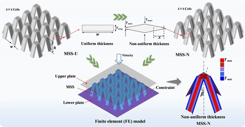
The nonlinear finite element platform LS-DYNA was implemented to establish a numerical model of the MSS, as shown in . The numerical model includes an upper plate, MSS, and lower plate. The lower plate is a fixed rigid wall, and the upper plate is a moved rigid wall with a constant crushing velocity. The MSS was modelled using a piecewise linear elastic-plastic strain hardening material, and the rigid wall was modelled using a rigid material. The numerical model was meshed using Belytschko-Tsay four-node shell elements, which exhibited five integration points in the thickness direction and one integration point in the plane direction. The static and dynamic contact friction coefficients during deformation are 0.3 and 0.2, respectively. Additionally, a non-uniform thickness in MSS-N was achieved by modifying the element thickness [Citation35]. A convergence analysis was conducted considering both computational efficiency and accuracy, the average unit size of 0.5 mm × 0.5 mm was used. This implies that the MSS contains a total of 20800 shell elements.
Figure 4. Numerical models of MSS-U and MSS-N.
4. Results and discussions
4.1. Experimental, theoretical and simulation results
The deformation modes of MSS were recorded at different times using an industrial camera. As shown in (a), initial plastic bending occurs on the inclined wall of the MSS. With the slow movement of the upper platform, MSS-N and MSS-U exhibited gradual folding patterns, similar to the collapsed form of conventional thin-walled structures. It is easy to find that the main plastic deformation of the test specimen occurs at the horizontal plastic hinge position of the inclined wall. As the crushing process progressed, the inclined wall gradually folded and eventually tended towards a compacted state. As shown in (b), the energy absorption curves exhibit high repeatability in all three sets of repeated tests, indicating that the preparation process of the MSS specimens is stable. To reveal the energy absorption mechanism of the MSS during the crushing process, the simplified theoretical folding models are presented in (d,e).
Figure 5. Experimental results: (a) Deformation modes with different displacements; (b) Energy absorption curves; (c) MSS specimens after crushing; (d) The diagram of bending energy dissipation; (e) The diagram of membrane energy dissipation.
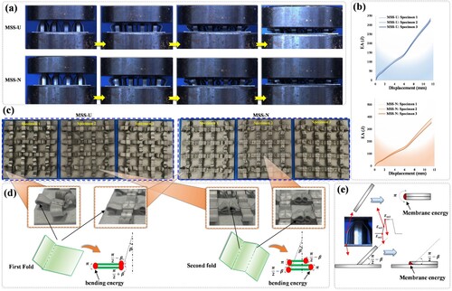
According to simplified folding theory, the energy dissipation of thin-walled structures mainly comprises the of bending energy and membrane energy
[Citation36]. The bending energy dissipation
during the folding process can be expressed as:
(4)
(4)
(5)
(5) where
denotes the plastic bending moment generated by the hinge lines,
denotes the rotation angle of the inclined wall during crushing process,
denotes the width of the inclined wall,
denotes the wall thickness and
denotes the plastic flow stress [Citation37]. For the MSS-U, the bending energy
can be expressed as:
(6)
(6)
(7)
(7) where
and
denote the numbers of inclined walls folded once and twice, respectively. According to the EquationEq. (1)
(1)
(1) , the expression of MSS-N for the bending energy
can be expressed as:
(8)
(8) A simple schematic of the membrane energy dissipation
is shown in (e). For the MSS-U, the membrane energy
generated at the connection position between the inclined wall and the fixed plate is as follows:
(9)
(9) where
denotes the number of connection positions between the inclined wall and the fixed plate. The membrane energy
generated by the inclined wall is:
(10)
(10) where
and
denote the numbers of inclined walls that undergo primary and secondary folding, respectively. The membrane energy
generated by the connection between the inclined wall and the upper plate is:
(11)
(11) where
denotes the number of connection positions between the inclined wall and the upper plate. Finally, the membrane energy of MSS-U can be expressed as:
(12)
(12)
(13)
(13) Similarly, the membrane energy of MSS-N can be expressed as:
(14)
(14)
(15)
(15) Owing to the difficulty in achieving ideal folding, folding efficiency and geometric interference need to be considered. Finally, the total energy dissipations
and
can be expressed as:
(16)
(16) where
denotes the crushing efficiency coefficient, which refers to the compaction strain.
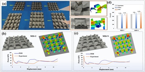
Furthermore, the mechanical response of the finite element numerical model is compared with the experimental results, and the final crushing deformation modes of the numerical simulation are found to be consistent with the experimental results, as shown in . The folding mode of the inclined wall of the MSS after crushing is similar to that in the numerical simulation ((a)). Additionally, the experimental crushing force trend after average processing is consistent with that in numerical simulation ((b,c)). The energy absorption results of the experiments, theoretical formulas, and finite element methods are shown in (d). It is found that the maximum error of the energy absorption obtained by the theoretical formula is less than 12% when compared to the experiment, and the maximum error of the energy absorption obtained by the finite element method is less than 15% when compared to the experiment. The factor causing errors in the theoretical formulas is the simplification of the plastic region for energy absorption, whereas the errors in the finite element analysis originate from material parameters, boundary conditions, and mesh accuracy. This study developed a theoretical model that can predict the energy absorption of the MSS with acceptable errors. The finite element numerical model established in this study has low computational errors. Furthermore, the numerical model established in this study satisfactorily captures the deformation mode and crushing force of the SMM. This indicates that the effectiveness of the numerical model established in this study has been verified, and thereby, it can be used for subsequent parametric analyses. It is also worth noting that MSS-N absorbs more energy than MSS-U while maintaining the same material mass. Further discussion is presented in Section 4.2.
Figure 6. Verification of numerical simulation models: (a) MSS specimens after crushing; (b) Deformation modes and crushing forces of MSS-U; (c) Deformation modes and crushing forces of MSS-N; (d) Comparison of energy absorption results between experiments, theoretical formulas, and finite element methods (FEM).
4.2. Parametric investigation
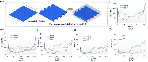
Triangular corrugated sandwich structures (CSS), as general sandwich structures, were used for comparison with the MSS in this Section. As shown in (a), the CSS can be regarded as a simple pose-changing origami configuration. The folding angle was analysed as an important parameter for controlling the posture of the sandwich structure. Specifically, the MSS and CSS exhibit the same mass. As (b–f), it is found that MSS-U and MSS-N exhibit higher load levels than CSS. Furthermore, MSS-U and MSS-N exhibit similar load trends in the initial crushing stage, and MSS-N exhibits a higher load level than MSS-U during the later crushing stage. Additionally, it is interesting to note that MSS-N and MSS-U exhibit a multi-stage load trend when the folding angle is between 15° and 30°, indicating that MSS has a multi-stage energy absorption potential.
Figure 7. Crushing forces of MSS and CSS: (a) Triangular corrugated sandwich structures; (b) Crushing forces at the folding angle of ; (c) Crushing forces at the folding angle of
; (d) Crushing forces at the folding angle of
; (e) Crushing forces at the folding angle of
; (f) Crushing forces at the folding angle of
.
To further explore the formation mechanism of load changes, the deformation modes at different crushing stages are shown in . The main energy dissipations of the MSS and CSS are concentrated near the folding hinge of the wall. Compared to CSS, MSS-U and MSS-N can realise more folding deformation, which implies that MSS has a higher energy dissipation potential during complete crushing, as energy dissipation is related to effective plastic zone deformation. Furthermore, it is interesting to note that when compared to the MSS with β = 10°, both MSS with β = 20° and β = 30° exhibit a delay in their second folding. Therefore, as the folding angle increases, the folding of MSS during the crushing process is more likely to exhibit a significant staged load effect, i.e. the load response generated by the first folding ends before starting another folding load response. shows the development trend of MSS with multi-stage crushing forces. The main crashworthiness performances of MSS and CSS at different folding angles are presented in (a). When the folding angle is in the design range of ∼
, the
, and
of the MSS and CSS slightly decrease with an increase of the folding angle. Unlike the CSS, the
of MSS increases initially and then decreases, reaching its maximum value when the folding angle is around
. This phenomenon can be attributed to the change in the global peak crushing force of MSS. As shown in (e), when the folding angle is
, the global peak crushing forces of MSS-U and MSS-N before compaction increase significantly and are higher than the initial peak forces.
Figure 8. Deformation modes of MSS and CSS: (a) Deformation modes of MSS-U; (b) Deformation modes of MSS-N; (c) Deformation modes of CSS; (d) Distribution of plastic regions for MSS-U and MSS-N.
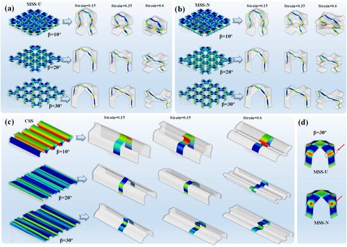
Figure 9. Crashworthiness performances of MSS and CSS: (a) Comparison of ,
, and
values between MSS and CSS with different folding angles; (b) Comparison of crushing force curves,
,
, and
values between MSS-U and MSS-N with different average thicknesses; (c) Comparison of crushing force curves,
,
, and
values between MSS-U and MSS-N with different maximum thicknesses; (d) Comparison of crushing force curves,
,
, and
values between MSS-U and MSS-N with different minimum thicknesses.
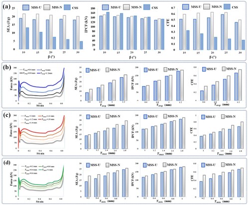
It can be observed that MSS-N can achieve excellent crashworthiness at different folding angles. The most significant difference between MSS-U and MSS-N is the distribution of the wall materials. By comparing (d), it is found that the maximum plastic strain of MSS-U occurs in the transverse position of the entire wall, whereas the maximum plastic strain of MSS-N occurs in the longitudinal position of the entire wall. Obviously, MSS-N is superior to MSS-U, which is attributed to the fact that the distribution of the variable thickness is beneficial for energy absorption. Therefore, further analysis is conducted on the crashworthiness characteristics of MSS-N under the influence of different size parameters. The main crashworthiness indicators of MSS-N with different average thicknesses , maximum thicknesses
, and minimum thicknesses
are summarised in (b–d). With an increase in the thickness parameters, the
,
, and
are increased monotonically. It should be noted that a significant increase in
is not conducive to crashworthiness, therefore, directly designing higher-thickness parameters cannot improve the overall crashworthiness performance.
Additionally, the crashworthiness performance changes in MSS due to the variation in the thickness parameters have also been examined. By continuously increasing the thickness value, the increasing trend of various crashworthiness indicators can be obtained, which can be used to clarify the performance indicator effects of the MSS when regulating the thickness parameters within a certain range. Compared to MSS-U, the increasing rates of various performance indicators of MSS-N under different thickness parameters are shown in (a). Here, the increasing rate () of MSS-N is expressed as:
(17)
(17) where
and
denote the crashworthiness values of MSS-N and MSS-U under the same thickness parameter, respectively. As shown in (a),
and
varied within the ranges of 0.6∼1.2 mm and 0.2∼1 mm, respectively. The increasing rate of all crashworthiness indicators decreases as the thickness increases. The gap in the crashworthiness indicators between MSS-U and MSS-N gradually narrowing, indicating that the advantage of MSS-N over MSS-U is weakening. However, when the thickness
changes in the range of 1∼1.8 mm, the increasing rate of all crashworthiness indicators increases as the thickness increases. The gap in the crashworthiness indicators between MSS-U and MSS-N gradually widens, indicating that the advantage of MSS-N over MSS-U is increasing. Although the
of MSS-N is higher than that of MSS-U, this relative increasing rate is slight. Therefore, it further demonstrates the advantages of MSS-N over MSS-U in the field of crashworthiness design.
Figure 10. Increasing rate of crashworthiness indicators when increasing thickness parameters: (a) Increase rate of performance indicators of MSS-N when compared to MSS-U under different thickness changes; (b) Increasing rate of various performance indicators of MSS-N with increasing thickness.
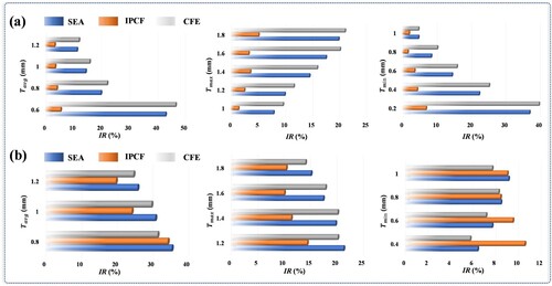
To further analyse the increasing rate of the crashworthiness indicators during the increasing change of thickness parameters in (b–d), (b) presents the increasing rate values of ,
, and
of MSS-N after changes in the equidistant thickness parameters. Here, the equidistant values of the thickness parameters
,
, and
corresponds to 0.2 mm. Similarly, the increasing rate (
) generated by the
th thickness parameter can be expressed as:
(18)
(18) where
and
denote the crashworthiness values corresponding to the
th and
th thickness values, respectively. It can be observed that with the increase in the thickness parameters, the increasing rates of
and
are significantly higher than those of
. Therefore, in the process of improving the levels of
and
by adjusting the thickness parameters, it is beneficial to avoid significantly increasing
to the maximum extent.
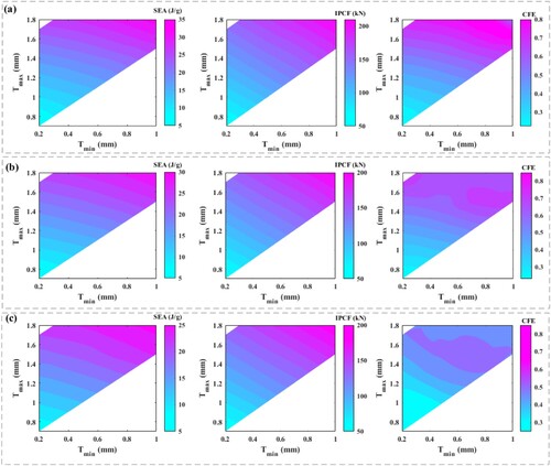
For the MSS-N, the variable thickness parameters are the key parameters for crashworthiness design. The crashworthiness performances of different folding angles by adjusting different variable-thickness parameters (maximum thickness , minimum thickness
) are shown in . It can be observed that both
and
can increase with an increase in the minimum and maximum thicknesses, showing significant monotonic characteristics. However, the
of MSS-N mainly reaches its maximum value near the design point of
= 0.8 mm and
= 1.6 mm. Therefore, the variable thickness parameters of MSS-N can be adjusted according to the performance requirements. In the aforementioned analysis and conclusions, the exploration of the matching scheme between the minimum and maximum wall thicknesses aids in determining the optimal mechanical properties of MSS-N.
Figure 11. Crashworthiness performances of MSS-N with respect to different thickness parameters: (a) ; (b)
; (c)
.
Furthermore, to discuss the potential of MSS for light weight and energy absorption, in this study, MSS was compared with existing energy-absorbing structures. shows the Ashby map of and equivalent material density. Different data points and corresponding envelope regions represent the approximate range that these lightweight mechanical structures can reach. The data is located approximately in the upper left corner, indicating a greater potential for lightweight and energy absorption. The analysis results indicate that the
of the proposed MSS is more competitive than that of the existing design schemes and can absorb more energy at the same density. It is expected that the MSS developed in this study will exhibit good potential for lightweight cushioning equipment designs.
Figure 12. Comparison of the reported in some existing structures: foam-filled aluminium alloy tube [Citation38]; square honeycomb [Citation39]; aluminium alloy foam [Citation40]; bio-inspired sandwich structure [Citation27]; stainless steel lattice [Citation41].
![Figure 12. Comparison of the SEA reported in some existing structures: foam-filled aluminium alloy tube [Citation38]; square honeycomb [Citation39]; aluminium alloy foam [Citation40]; bio-inspired sandwich structure [Citation27]; stainless steel lattice [Citation41].](/cms/asset/9ecc19b4-207a-4cec-a225-6d83ed3a191f/nvpp_a_2285894_f0012_oc.jpg)
5. Application scenarios
These above research results indicate that the proposed MSS design method was implemented in the metal-printed specimens. Additive manufacturing technology provides opportunities for the design of different materials and macroscopic topologies, so MSS can be made into different materials and macroscopic topologies, and applied to specific protective equipment. To better demonstrate the superiority and feasibility of the proposed MSS in guiding the design of lightweight cushioning equipment, the application of the MSS in different scenarios (automobile and plant protection drone) is analysed in Section 5.
5.1. Layered design: collision protection of automobiles
Traffic collisions always cause harm to human life, as shown in (a). In car collisions, the traditional anti-collision beam (ACB) is the main energy-absorbing component. The ACB of a vehicle is composed of a crossbeam, left and right energy-absorption boxes, and connecting plates. The crashworthiness of anti-collision beam directly determines its ability to protect passengers and key components in the event of a traffic collision accident. Therefore, the design of an effective anti-collision beam structure with excellent cushioning performance is of great significance.
Figure 13. Protective structure of automobiles: (a) Schematic diagram of car collisions during driving; (b) Crushing results of the filled anti-collision beam.
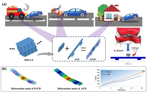
In this study, the MSS is stacked to form an ordered lattice structure (MSS-LS) and filled into an ACB to form a filled anti-collision beam (FACB). The folding angle of MSS-LS is 10°. The maximum span of FACB, the length and width of the beam section are 1100, 120, and 30 mm, respectively. A three-point bending test simulation is performed to analyse the anti-collision characteristics of the FACB [Citation42], and the main load conditions are shown in (a). The wall thickness of FACB and MSS-LS is 2.25 and 0.3 mm, respectively. The FACB and ACB have the same weight of 2.56 kg. Aluminium alloy is defined as the material of the anti-collision beam [Citation43]. As shown in (b), the energy absorption of FACB is 38% higher than that of ACB, i.e. filling the car collision beam with the MSS-LS can increase the energy absorption when resisting obstacles. The analysis results indicate that the MSS has potential applications in the field of automotive crashworthiness design. This only represents a test of a design example, and it can be anticipated that more competitive crashworthiness design solutions can be tailored through optimisation methods.
5.2. Sandwich sleeve: landing protection of plant protection drones
The working environment of plant protection drones is complex, particularly on the ground in mountainous areas, which poses challenges to their landing of plant protection drones. Extreme impact behaviours due to improper operation or environmental impacts can cause irreversible damage to plant protection drones (such as component failure, reduced reliability, and electronic devices on fire), as shown in (a). Therefore, this study introduces the MSS into the design of a plant protection drone. By rolling the MSS, a novel sandwich sleeve configuration was formed to serve as a cushioning protection device for the bracket of plant protection drones.
Figure 14. Landing protective device of plant protection drones: (a) Potential hazards of plant protection drones during landing; (b) The MSS protection device.
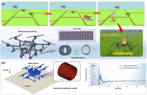
A simplified finite element model is shown in (b). The folding angle, thickness, length, and diameter of the MSS protection device are 10°, 0.8, 60, and 80 mm, respectively. Assuming that the plant protection drone is in free fall at an initial velocity of 3.13 m/s, the results of whether it is equipped with an MSS protection device were studied. Here, the plant protection drone is considered a rigid body, and the MSS protection device uses resin material [Citation44]. The plant protection drone generates an impact force when it contacts the ground. These data indicate that the protective structure of the MSS can effectively reduce the initial peak crushing force by 48%. It is evident that installing an MSS protection device on the bracket of a plant protection drone is beneficial for reducing the ground crushing force. This implies that the MSS protection device is expected to reduce mechanical damage to plant protection drones and improve their service life. Here, only a free-fall condition was implemented, but it does not prevent understanding the feasibility of MSS in the protection device design. In this case, it is possible to improve the overall protection performance of MSS by considering the multiple landing conditions of plant protection drones.
6. Conclusions
Novel ultralight meta-sandwich structures inspired by Kirigami (MSS) are proposed and fabricated using laser powder bed fusion (LPBF) technology in this study. To reveal the mechanical properties of the MSS, experiments, theoretical analyses, and finite element simulations are used to analyse the meta-sandwich structures inspired by Kirigami with uniform (MSS-U) and non-uniform thicknesses (MSS-N). The main conclusions are as follows:
The experimental results indicate that the main plastic deformations of MSS-U and MSS-N occur at the horizontal plastic hinge position of the inclined wall. As the crushing process progresses, the inclined wall gradually folds in order and eventually tends towards a compacted state. Meanwhile, MSS-N absorbs more energy than MSS-U while maintaining the same material mass.
Based on the simplified folding theory model, the energy absorption prediction formulas for MSS-U and MSS-N are successfully derived by extracting the experimental deformation features. The accuracy of the derived theoretical formula is verified by comparing the results of the experiment with those of finite element analysis, and the maximum error with the experiment is less than 12%.
Compared to the conventional corrugated sandwich structure, the MSS achieves better crashworthiness indicators and more folding numbers. It is found that the minimum/maximum thickness and the folding angle have a significant influence on the crashworthiness responses. The mechanical properties of MSS-N can be regulated by changing the folding angle while maintaining the same thickness. Additionally, the
of the MSS is more competitive than that of the existing design schemes and can absorb more energy at the same density.
The feasibility of applying MSS to automobiles and plant protection drones is verified by changing different materials and macroscopic topological configurations. Compared with traditional hollow anti-collision beams, the design scheme filled with MSS-LS can increase the energy absorption by 38%, and installing the MSS protective device on the bracket of plant protection drones can significantly reduce the initial peak crushing force during landing by 48%.
In summary, experiments, theoretical derivations, and numerical simulations are performed for the MSS in this study. Potential application scenarios (automobiles and plant protection drones) of the MSS are also verified. The design method proposed in this study can provide innovative guidance for the design of novel crushing protective materials and structures for engineering equipment.
Disclosure statement
No potential conflict of interest was reported by the author(s).
Data availability
Data available on request from the authors.
Additional information
Funding
References
- Habib FN, Iovenitti P, Masood SH, et al. In-plane energy absorption evaluation of 3D printed polymeric honeycombs. Virtual Phys Prototyp. 2017;12:117–31. doi:10.1080/17452759.2017.1291354
- Zhang Y, Aiyiti W, Du S, et al. Design and mechanical behaviours of a novel tantalum lattice structure fabricated by SLM. Virtual Phys Prototyp. 2023;18:e2192702. doi:10.1080/17452759.2023.2192702
- Isaac CW, Duddeck F. Recent progress in 4D printed energy-absorbing metamaterials and structures. Virtual Phys Prototyp. 2023;18:e2197436. doi:10.1080/17452759.2023.2197436
- Fan W, Xie R, Davidson M, et al. Crashworthiness and energy absorption of UHPFRC-steel composite sandwich structures under impact loading. Compos Struct. 2023;311:116813. doi:10.1016/j.compstruct.2023.116813
- Ning H, Janowski GM, Vaidya UK, et al. Thermoplastic sandwich structure design and manufacturing for the body panel of mass transit vehicle. Compos Struct. 2007;80:82–91. doi:10.1016/j.compstruct.2006.04.090
- Yu, Z., Liu, K., Zhou, X., and Jing, L. 2023. “Low-velocity impact response of aluminum alloy corrugated sandwich beams used for high-speed trains” Thin-Walled Struct 183: 110375. doi:10.1016/j.tws.2022.110375
- Hara D, Özgen GO. Investigation of weight reduction of automotive body structures with the Use of sandwich materials. Transp Res Procedia. 2016;14:1013–20. doi:10.1016/j.trpro.2016.05.081
- Wang J, Shi C, Yang N, et al. Strength, stiffness, and panel peeling strength of carbon fiber-reinforced composite sandwich structures with aluminum honeycomb cores for vehicle body. Compos Struct. 2018;184:1189–96. doi:10.1016/j.compstruct.2017.10.038
- Pan J, Fang H, Xu MC, et al. Dynamic performance of a sandwich structure with honeycomb composite core for bridge pier protection from vehicle impact. Thin-Walled Struct. 2020;157:107010. doi:10.1016/j.tws.2020.107010
- Xu X, Zhang Y, Wang X, et al. Searching superior crashworthiness performance by constructing variable thickness honeycombs with biomimetic cells. Int J Mech Sci. 2022;235:107718. doi:10.1016/j.ijmecsci.2022.107718
- Acanfora V, Sellitto A, Russo A, et al. Experimental investigation on 3D printed lightweight sandwich structures for energy absorption aerospace applications. Aerosp Sci Technol. 2023;137:108276. doi:10.1016/j.ast.2023.108276
- Le VT, Ha NS, Goo NS. Advanced sandwich structures for thermal protection systems in hypersonic vehicles: a review. Compos Part B Eng. 2021;226:109301. doi:10.1016/j.compositesb.2021.109301
- Tewari K, Pandit MK, Budarapu PR, et al. Analysis of sandwich structures with corrugated and spiderweb-inspired cores for aerospace applications. Thin-Walled Struct. 2022;180:109812. doi:10.1016/j.tws.2022.109812
- Palomba G, Epasto G, Crupi V. Lightweight sandwich structures for marine applications: a review. Mech Adv Mater Struct. 2022;29:4839–64. doi:10.1080/15376494.2021.1941448
- Tuswan T, Abdullah K, Zubaydi A, et al. Finite-element analysis for structural strength assessment of marine sandwich material on ship side-shell structure. Mater Today Proc. 2019;13:109–14. doi:10.1016/j.matpr.2019.03.197
- Qiu Y, Yan R, Shen W, et al. Load-bearing characteristics of marine complex sandwich composites considering unequal elastic modulus in tension and compression. Marine Structures. 2023;89:103382. doi:10.1016/j.marstruc.2023.103382
- Zhou Y, Xue B, Guo Y, et al. Mechanical responses of CFRP/PVC foam sandwich plate impacted by hailstone. Int J Impact Eng. 2023;178:104631. doi:10.1016/j.ijimpeng.2023.104631
- Sun H, Yuan H, Zhang J, et al. Dynamic response of multilayer sandwich beams with foam-filled trapezoidal corrugated and foam cores under low-velocity impact. Eng Struct. 2023;286:116080. doi:10.1016/j.engstruct.2023.116080
- Khaire N, Gupta M, Tiwari G. Blast resistance of graded aluminium foam core sandwich structure against blast loading. Mater Today Proc. 2023. doi:10.1016/j.matpr.2023.03.220
- Lin G, Li J, Li F, et al. Low-velocity impact response of sandwich composite panels with shear thickening gel filled honeycomb cores. Compos Commun. 2022;32:101136. doi:10.1016/j.coco.2022.101136
- Aryal B, Morozov EV, Wang H, et al. Effects of impact energy, velocity, and impactor mass on the damage induced in composite laminates and sandwich panels. Compos Struct. 2019;226:111284. doi:10.1016/j.compstruct.2019.111284
- Zhang J, Yuan H, Li J, et al. Dynamic response of multilayer curved aluminum honeycomb sandwich beams under low-velocity impact. Thin-Walled Struct. 2022;177:109446. doi:10.1016/j.tws.2022.109446
- St-Pierre L, Fleck NA, Deshpande VS. The dynamic indentation response of sandwich panels with a corrugated or Y-frame core. Int J Mech Sci. 2015;92:279–89. doi:10.1016/j.ijmecsci.2014.11.021
- Cheng Y, Liu K, Li Y, et al. Experimental and numerical simulation of dynamic response of U-type corrugated sandwich panels under low-velocity impact. Ocean Eng. 2022;245:110492. doi:10.1016/j.oceaneng.2021.110492
- He W, Liu J, Wang S, et al. Low-velocity impact behavior of X-Frame core sandwich structures – Experimental and numerical investigation. Thin-Walled Struct. 2018;131:718–35. doi:10.1016/j.tws.2018.07.042
- Yang X, Ma J, Shi Y, et al. Crashworthiness investigation of the bio-inspired bi-directionally corrugated core sandwich panel under quasi-static crushing load. Mater Des. 2017;135:275–90. doi:10.1016/j.matdes.2017.09.040
- Huang H, Yang X, Yan Q, et al. Crashworthiness analysis and multiobjective optimization of bio-inspired sandwich structure under impact load. Thin-Walled Struct. 2022;172:108840. doi:10.1016/j.tws.2021.108840
- Qi J, Li C, Tie Y, et al. Energy absorption characteristics of origami-inspired honeycomb sandwich structures under low-velocity impact loading. Mater Des. 2021;207:109837. doi:10.1016/j.matdes.2021.109837
- Zhang J, Lu G, Zhang Y, et al. A study on ballistic performance of origami sandwich panels. Int J Impact Eng. 2021;156:103925. doi:10.1016/j.ijimpeng.2021.103925
- Zhang Z, Song B, Fan J, et al. Design and 3D printing of graded bionic metamaterial inspired by pomelo peel for high energy absorption. Chin J Mech Eng Addit Manuf Frontiers. 2023;2:100068. doi:10.1016/j.cjmeam.2023.100068
- Jiang H, Le Barbenchon L, Bednarcyk BA, et al. Bioinspired multilayered cellular composites with enhanced energy absorption and shape recovery. Addit Manuf. 2020;36:101430), doi:10.1016/j.addma.2020.101430
- Maskery I, Aboulkhair NT, Aremu AO, et al. Compressive failure modes and energy absorption in additively manufactured double gyroid lattices. Additive Manufacturing. 2017;16:24–29. doi:10.1016/j.addma.2017.04.003
- Yin H, Zhang W, Zhu L, et al. Review on lattice structures for energy absorption properties. Compos Struct. 2023;304:116397. doi:10.1016/j.compstruct.2022.116397
- Yue Z, Han B, Wang Z, et al. Data-driven multi-objective optimization of ultralight hierarchical origami-corrugation meta-sandwich structures. Compos Struct. 2023;303:116334. doi:10.1016/j.compstruct.2022.116334
- Pang T, Zheng G, Fang J, et al. Energy absorption mechanism of axially-varying thickness (AVT) multicell thin-walled structures under out-of-plane loading. Eng Struct. 2019;196:109130. doi:10.1016/j.engstruct.2019.04.074
- Luo Y, Fan H. Investigation of lateral crushing behaviors of hierarchical quadrangular thin-walled tubular structures. Thin-Walled Struct. 2018;125:100–06. doi:10.1016/j.tws.2018.01.016
- Huang W, Zhang Y, Xu Y, et al. Out-of-plane mechanical design of bi-directional hierarchical honeycombs. Compos Part B Eng. 2021;221:109012. doi:10.1016/j.compositesb.2021.109012
- Zhu G, Wang Z, Huo X, et al. Experimental and numerical investigation into axial compressive behaviour of thin-walled structures filled with foams and composite skeleton. Int J Mech Sci. 2017;122:104–119. doi:10.1016/j.ijmecsci.2016.12.019.
- Côté F, Deshpande VS, Fleck NA, et al. The out-of-plane compressive behavior of metallic honeycombs. Mater Sci Eng A. 2004;380:272–80. doi:10.1016/j.msea.2004.03.051
- Yan LL, Zhao ZY, Han B, et al. Tube enhanced foam: a novel way for aluminum foam enhancement Mater Lett. 2018;227:70–73. doi:10.1016/j.matlet.2018.04.115
- Yang W, Xiong J, Feng L-J, et al. Fabrication and mechanical properties of three-dimensional enhanced lattice truss sandwich structures. J Sandwich Struct Mater. 2018;22:1594–611. doi:10.1177/1099636218789602
- Sun G, Wang X, Fang J, et al. Parallelized optimization design of bumper systems under multiple low-speed impact loads. Thin-Walled Struct. 2021;167:108197. doi:10.1016/j.tws.2021.108197
- Xu X, Zhang Y, Wang J, et al. Crashworthiness design of novel hierarchical hexagonal columns. Compos Struct. 2018;194:36–48. doi:10.1016/j.compstruct.2018.03.099
- Wang J, Luo X, Wang K, et al. On impact behaviors of 3D concave structures with negative Poisson’s ratio. Compos Struct. 2022;298:115999. doi:10.1016/j.compstruct.2022.115999