
 ?Mathematical formulae have been encoded as MathML and are displayed in this HTML version using MathJax in order to improve their display. Uncheck the box to turn MathJax off. This feature requires Javascript. Click on a formula to zoom.
ABSTRACT
Balancing strength and ductility is crucial for structural materials, yet often presents a paradoxical challenge. This research focuses on crafting a unique bimetallic structure, combining non-magnetic, stainless steel 316L (SS316L) with limited strength but enhanced ductility and magnetic, martensitic 17–4 PH with higher strength but lower ductility. Utilising a powder-based laser-directed energy deposition (L-DED) system, two vertical bimetallic configurations (SS316L/17-4 PH) and a radial bimetallic structure (SS316L core encased in 17–4 PH) were fabricated. Monolithic SS316L, 17–4 PH, and a 50% SS316L/50% 17–4 PH mixture were printed. The printed samples’ phase, microstructure, room temperature mechanical properties, and fracture morphology were examined in as-printed conditions. Bimetallic samples exhibited both phases, with a smooth grain transition at the interface. Radial bimetallic samples demonstrated higher mechanical strength than other compositions, except 17–4 PH. These findings showcase the potential of the L-DED approach for creating functional components with tailored mechanical properties.
1. Introduction
Ancient human progress, initially driven by natural materials such as bone, wood, and shells, eventually witnessed the ascendancy of synthetic alloys and compounds, marking the onset of an era characterised by considerable augmented performance. The scientific and engineering communities are still fascinated by the intricate beauty of natural structures known for their elegance and complexity. These structures often possess exceptional attributes and mechanical properties that far surpass those of their constituent elements by several orders of magnitude [Citation1]. Take, for instance, the awe-inspiring qualities of natural structures like tooth enamel and nacre [Citation2–5] – rich in minerals and mainly ceramic. They skillfully combine distinct structures to create robust surface layers that resist wear and penetration while maintaining a flexible subsurface, hence germinating the idea of developing multi-material layered structures in the vertical direction. Another symphony of nature unfolds within the union of cancellous bone ensconced by cortical bone [Citation6], a multidimensional, multi-material structure with a planar variation along the build direction, where material diversity influences mechanical properties in various dimensions. The pursuit of unlocking the full potential of multi-material configurations continues to captivate the scientific frontier as they embark on crafting biomimetic designs.
The evolution of multi-material structures presents many advantages, expanding the scope of potential applications beyond what traditional materials can offer [Citation7]. Within multi-material structures, bimetallic compositions predominantly involve the fusion of two distinct metals. This union primarily aims to harness the diverse and unique properties inherent to each of the metals. These properties encompass a wide range, including thermo-physical attributes, mechanical characteristics, electrical conductivity, optical properties, and resistance to corrosion and oxidation. However, the pursuit of replicating these marvels presents a formidable challenge due to disparities in chemical, metallurgical, or thermo-physical properties. Simultaneously, contemporary manufacturing techniques for multi-material structures primarily rely on processes such as rolling overlapping sheets or utilising methods like rotary friction welding (RFW) and friction stir processing (FSP) [Citation8–12]. While effective for producing standard and uncomplicated components, these techniques prove inefficient and constraining in their applicability across modern industries. It's important to note that components produced through FSP and RFW are susceptible to issues such as a high heat-affected zone (HAZ) and welding defects, including distortion and cracking [Citation12]. In contrast, metal additive manufacturing (AM) is a paradigm-shifting alternative to conventional processing methods, gaining momentum due to maximum design flexibility in compositional variation, tool-free production, on-demand customisation, and a remarkable transition from functional prototyping to direct manufacturing [Citation13, Citation14]. While additive manufacturing (AM) continues to push the boundaries of conventional techniques, the predominant focus in literature remains on single-material compositions[Citation15]. In this context, metal AM is primed to spearhead a revolution in the fabrication of complex multi-material systems[Citation16]; a need exists for additional research in AM of multi-material components.
Directed energy deposition (DED) stands out for powder and wire as feedstock materials powered by a laser, electric arc, or electron beam. Among the spectrum of DED techniques, the powder-based laser DED (L-DED) method distinguishes itself by synergizing the precise energy of a laser with the controlled delivery of metal powders[Citation17, Citation18]. With the advancement of technology in the field of DED AM, location and application-specific structures have gained popularity in various industries like energy, automotive, aerospace, nuclear, transport, and biomedical [Citation19–23]. Multi-material and bimetallic AM are one of the verticals of the L-DED, where more than one material is printed in a single operation [Citation7]. The outcome of this process yields components that not only transcend the limitations inherent to each material but also seamlessly amalgamate the desired properties of each material within a singular structure [Citation12]. L-DED offers the flexibility to create multi-material components using various powder compositions, tailoring them to serve specific functionalities [Citation15]. Although most research on bimetallic and multi-material structures [Citation24–27] focused on modifications along the vertical dimension, there remains a notable gap in the literature regarding the production of multidimensional bimetallic structures characterised by complex radial interfaces in the horizontal plane, while maintaining consistency in the vertical direction.
Affordability [Citation28] and good corrosion resistance made austenitic SS316L viable for multiple functions ranging from offshore marine-based applications to biomedical devices; the limited mechanical properties make it challenging to use in sectors requiring high mechanical properties [Citation29]. Enhanced strength and hardness, superior corrosion resistance, outstanding fatigue behaviour, and minimal warpage are the properties associated with martensitic 17- 4 PH [Citation30]. Although these properties make it viable to be used in the sectors demanding enhanced mechanical properties, cost-effectiveness remains a challenge. While the majority of prior studies concentrated on either printing monolithic SS316L [Citation31–33] or monolithic 17-4PH [Citation30, Citation34, Citation35], a noticeable knowledge gap on the interaction between the two remains unaddressed.
The present research is concentrated on the development of innovative multidimensional bimetallic structures by complex radial interfaces in the horizontal plane while maintaining consistency in the vertical direction, devoid of defects, that combine the martensitic properties of 17–4 PH with the austenitic attributes of SS316L, employing the L-DED technique. A comprehensive investigation was conducted to pursue this objective involving fabricating several distinct structures. These encompassed three monolithic configurations: SS316L, 17-4PH, and a 1:1 premix of SS316L and 17–4 PH. Additionally, two vertical bimetallic configurations were printed, each combining SS316L and 17–4 PH, alongside a radial bimetallic structure featuring an SS316L core enclosed within a 17–4 PH casing. To facilitate comprehensive analysis, two distinct sets of samples were generated. One set was designated for mechanical testing and subsequent analysis, while the other was allocated for comprehensive materials characterisation. The broader impact of the current research lies in location-specific applications such as aerospace structures, turbomachine blades, oil rigs, marine-based structures, biomedical devices, and nuclear waste containers.
2. Materials and methods
2.1. Powder-based laser-DED of SS316L and 17-4 PH samples
SS316L powders (Höganäs, Sweden) possessing a particle size distribution spanning from 53 to 150 µm and 17–4 PH powders (Carpenter Tech. Corp., PA) characterised by an average particle size range of 15–53 µm were utilised as feedstock materials for this study. The elemental composition of the feedstock powders is presented in supplementary Table ST 1.
A L-DED metal AM system, FormAlloy (Spring Valley, CA), featuring dual powder feeders and a 1-kilowatt fibre laser, as shown in a and b, was employed to print different compositions of SS316L and 17–4 PH. The L-DED system consists of an actively cooled build platform that can move in a planar direction of X and Y coordinates, while the 1 kW laser source is mounted on the Z-spindle perpendicular to the build platform. To mitigate oxidation, the L-DED metal AM system operates within an argon environment to maintain oxygen levels below 15 ppm. The DED system utilises a continuous fibre laser beam that reaches a laser power of up to 1 kW, effectively melting deposited powders onto a substrate. The schematics of the fabrication of the bimetallic sample are represented in c.
Figure 1. (a), (b) L-DED setup used for sample fabrication, (c) schematics of the L-DED process for fabricating the SS316L – 17- 4 PH bimetallic structures, (d) processing parameters of the L-DED, (e) schematics of various samples fabricated via L-DED with dimensions.
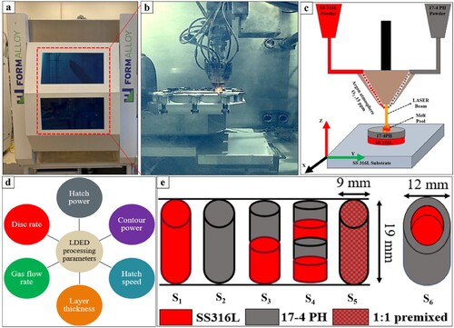
To print the monolithic and bimetallic structures of the SS316 L and the 17–4 PH, computer-aided design (CAD) files with the required dimensions were uploaded to the computer-aided manufacturing (CAM) software to generate the necessary toolpath. As the formation of defects, including porosity, lack of fusion (LOF), and keyhole defects during the printing process, can substantially influence the mechanical properties and potentially compromise the reliability of the as-printed components [Citation36, Citation37] numerous manufacturing trials were undertaken in this research. These trials were conducted before the final printing stage to achieve optimal and refined processing parameters, as illustrated in d. The printed compositions encompassed monolithic SS316L, 17–4 PH, single-layer, multi-layer vertical bimetallic, and radial bimetallic of SS316L and 17–4 PH, and a 1:1 premixed blend of SS316L and 17–4 PH.
represents the comprehensive optimal print parameters for all compositions. This table also depicts the volumetric energy density (Ev), which signifies the energy supplied by the laser power source to the powder volume [Citation26, Citation38]. This relationship is expressed by the equation provided below.
(1)
(1) Where v is scanning speed (mm/s), h is hatch spacing (mm), which was equal to 0.5 for all samples, t is layer thickness (mm), and P is laser power (W).
Table 1. Optimised process parameters and compositional nomenclature of the various samples manufactured through powder-based L-DED process.
2.2. Phase analysis and microstructural characterisation
Samples with 12 mm X 12 mm X 6 mm were printed for microstructural characterisation, phase distribution, and hardness analysis. The printed monolithic and bimetallic samples of SS316L and 17–4 PH were cut longitudinally using a low-velocity diamond saw, ground using silicon carbide papers of 80–2000 grit sizes, and polished with a suspension of 1-0.05 μm Al2O3/DI water for 15 min each. The samples were scanned for analysis using a Rigaku mini flex 600 X-ray Diffractometer, which was equipped with a 2-D General Area Diffraction Detector (GADDS) mounted on a theta-theta goniometer and scanned using Cu k-alpha radiation (1.54 angstroms at 40 kV and 20 mA) at a speed of 5° per minute over the range of 35° to 100° of 2θ. The raw data obtained was processed using Rigaku PDXL software. The microstructural analysis was performed on the mirror-polished surfaces of the monolithic and bimetallic samples of SS316L and 17–4 PH. Before the microstructure analysis, the samples were etched by submerging them in a mixture of 10 ml HNO3, 15 ml HCl, 10 ml CH3COOH, and 2–5 drops of glycerol [Citation39] for 30–45 s. The etched metallographic samples were analyzed under the digital optical microscope (Keyence VHX 7000 series) and field-emission scanning electron microscope (SEM, Apreo VolumescopeTM, Thermo Fisher Scientific, Waltham, MA) for macro and microstructures, respectively, at various magnifications.
2.3. Hardness and compression testing
Monolithic samples S1, S2, and S5, with a diameter of 9 mm and a height of 18 mm, were printed for compression testing. Likewise, sample S3 has a 19 mm height with 9.5 mm of 17–4 PH deposited on 9.5 mm of printed SS316L, while sample S4 has the same height, with each printed layer having a thickness of 1.5 mm printed alternatively. Sample S6 has an inner radius of 1.5 mm of SS316L and an external radius of 6 mm with a height of 18 mm. The compression specimens were further machined to give a dimension of 7 mm diameter and 14 mm height. The Vicker's cross-sectional hardness profile was obtained along the build direction of the samples from the bottom zone to the top zone using a Phase II Plus Micro Vickers hardness tester (Upper Saddle River, NJ, USA) with an application of 1.961 N load (HV0.2), for 15 s dwell time. 50–60 indents were made in each zone to ensure comprehensive data collection. The compression specimens were prepared by milling the outer surface and turning the cross-sectional area by a 4-axis mill-turn set up according to the ISO/ASTM E9-19 standard [Citation40] with ∼14 mm gauge length and ∼7 mm diameter to evaluate the mechanical properties. The quasi-static compression test was performed on the specimens using the Instron servo-hydraulic universal testing machine (135 kN load cell) at room temperature with a 0.1 mm/min crosshead speed. The load application for all the specimens was parallel to the build direction. In order to maintain statistical significance, a minimum of three samples from each composition were tested under a quasi-static environment for compression.
3. Results and discussion
The ensuing section describes the phase () and microstructural analysis ( and ) of the monolithic, vertical, and radial bimetallic structures. These analyses used X-ray diffraction (XRD), optical, and SEM. Microhardness assessments () and compression tests () were carried out on all specimens under ambient conditions. Fractographic analysis () of failed specimens was conducted using SEM.
Figure 2. XRD of monolithic SS316L, 17–4 PH, bimetallic of SS316L and 17-PH, and 1:1 premix with scanning direction along the build direction (BD).
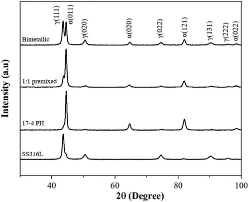
Figure 3. (a) Stereoscope image of the monolithic SS316L, (a1) High magnification optical image showing the interface between the substrate and the printed SS316L without any defect and unmelted powders, (a2, a3) cellular and cellular dendritic microstructure present in the SS316L print, (a4) dendritic microstructure of SS316L, (b) Stereoscope image of the monolithic 17–4 PH, (b1), Low magnification optical image showing the interface between the substrate and the printed 17–4 PH without any defect and unmelted powders, (b2, b3, b4) low and high magnification optical and SEM image of the microstructure of 17–4 PH, (c) Stereoscope image of the printed 1:1 premixed sample, (c1) Low magnification optical image showing the interface between the substrate and the printed 1:1 premixed sample without any defect and unmelted powders, (c2) High magnification image of the hemispherical patterns from the laser deposition, (c3) SEM image of the 1:1 premixed sample showing dendritic microstructure and lathy martensite present within same layer, (c4) SEM image showing δ – ferrite of the 1:1 specimen.
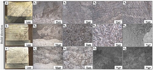
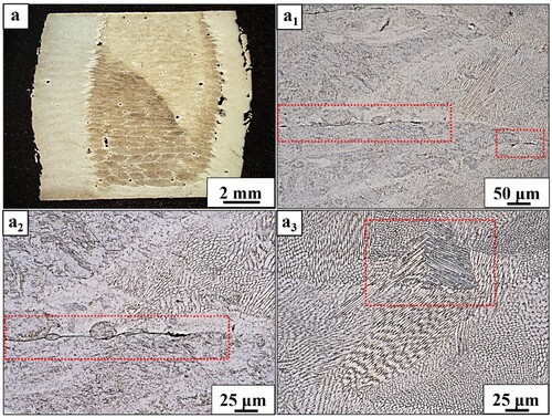
Figure 4. (a) Stereoscope image of the vertical bimetallic specimen showing the distinct regions of SS316L (bright zones) and the 17–4 PH (dark zone), (a1, a2) low and high magnification images showing the smooth transition from SS316L to 174 PH, (b) the unique wedge-shaped interlocking microstructure of the radial bimetallic with SS316L core and 17–4 PH casing, (b1, b2) low and high magnification images showing the interlocking pattern of radial bimetallic.
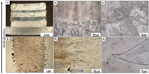
Figure 5. Hardness profile of monolithic SS316L, 17–4 PH, bimetallic of SS316L and 17-PH, and 1:1 premix with scanning direction along the build direction (BD).
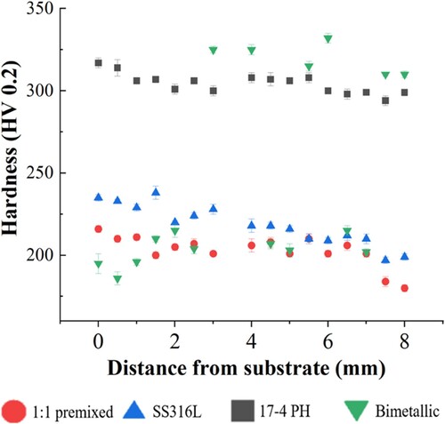
Figure 6. (a) Stress vs. strain curve for monolithic SS316L, 17–4 PH, 1:1 premix, single layer vertical bimetallic, multi-layer vertical bimetallic and radial bimetallic of SS316L and 17–4 PH, (b) Compressive Yield strength of the respective specimens – S1 to S6.
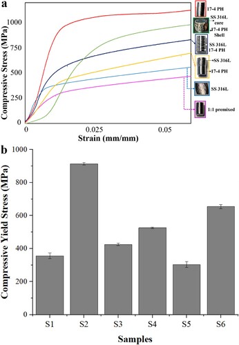
Figure 7. (a) Stereoscope image of the SS316L specimen after compression testing, (a1, a2) optical image of the post-compression SS316L showing the flow of grains, (a3, a4) SEM image showing the flow of grains post compression, (b) Stereoscope image of the 17–4 PH specimen after compression testing, (b1) optical image of the post-compression 17–4 PH showing cracks, (b2, b3, b4) SEM images showing cracks in the microstructure monolithic 17–4 PH at different magnifications post-compression, (c) stereoscope image of the 1:1 premixed specimen after compression testing, (c1) optical image showing deflated hemispherical deposits post compression, (c2) δ – ferrite microstructure in the compressed monolithic 1:1 premixed specimen, (c3) deformation slip lines present in the austenite grains of the 1:1 premixed sample post compression.
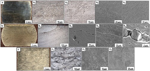
Figure 8. (a) Stereoscope image of the single layer bimetallic specimen after compression testing showing outward bulge in the SS316L, while the 17–4 PH region remains almost straight, (a1, a2, a3) low magnification and high magnification of the interface of the compressed single layer bimetallic sample showing the crack at the interface of the SS316L and the 17–4 PH, (b) Stereoscope image of the multi-layer bimetallic specimen after compression testing showing outward bulge in all the SS316L region, (b1, b2, b3) low magnification and high magnification of the interface of the compressed multi-layer bimetallic sample showing the crack at the interface of the SS316L and the 17–4 PH.
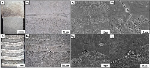
Figure 9. (a) Stereoscope image of the compressed macrostructure of the radial bimetallic specimen showing the bulging, (a1, a2) low magnification and high magnification of the interface of the compressed radial bimetallic sample showing the crack at the interface of the SS316L core and the 17–4 PH casing, (a3) twinning of the SS316L microstructure post compression.
3.1. Phase analysis
The X-ray diffraction (XRD) measurements were carried out on the monolithic and bimetallic samples to discern the phases in the regions along the build direction (BD). The XRD results of the bulk monolithic SS316L, 17–4 PH, 1:1 premixed, and the bimetallic samples printed via L-DED are shown in , while the detailed calculations for corresponding phase fractions in each of the samples are depicted in Tables ST 2, ST 3, ST 4 and ST 5.
As illustrated in , the primary phase present in the monolithic SS316L sample is the face-centered cubic (FCC) austenite (JCPDS 96-900-8470). The monolithic SS316L sample showed a preferred orientation along the (111) plane of the austenite phase at an angle of 2θ equals 43.63°. There has been no trace of δ-ferrite formation observed in the sample. This can be attributed to the rapid cooling rate and higher scanning speed. Similar results have been reported, where the formation of δ-ferrite was mitigated by introducing a scanning speed larger than 600 mm/min [Citation31]. Also, the rapid cooling rate restricts the solid-state diffusion of carbon and the solid-state phase transformation of FCC to body-centered cubic (BCC) [Citation41], impeding the δ-ferrite phase formation.
The primary phase in monolithic 17–4 PH was BCC martensite (JCPDS 96-901-3475). The sample showed a preferred orientation along the (011) plane at 44.62° of 2θ. No austenite phase was observed in the diffractogram pattern. This contradicts the results reported by other groups [Citation42, Citation43] where the presence of retained austenite phase in the as-printed samples of 17–4 PH is reported. One possible explanation for getting the pure martensitic phase is the rapid cooling and processing technique for printing the 17–4 PH samples. A four-second delay time was employed between each consecutive layer, which allowed the print to solidify over a longer period. This additional time, along with rapid cooling, promotes the formation of martensite and suppresses the austenite [Citation34]. The X-ray pattern of the 1:1 premixed and the bimetallic samples shows both martensite and austenite peaks. The 1:1 premixed sample showed preferred orientation along the (011) BCC martensite plane at an angle of 44.52°. The intensity of the (111) austenite peak was less prominent for this sample, . This can be attributed to the net reduction of the volume percentage of Ni in the premixed powder. Mixing the SS316L and 17–4 PH powder in a 1:1 ratio reduced Ni by 30% while keeping the Cr almost the same. Ni is an austinite stabiliser [Citation44], and by reducing the volume fraction of Ni, the austenite transformation was suppressed in the bulk structure of 1:1 bimetallic. The austenite percentage in the 1:1 premixed sample was 27.01%. The bimetallic structure of SS316L and 17–4 PH showed equal preferred orientation along the (111) plane of the austenite and (011) plane of the martensite at 2θ of 43.63°, and 44.56°, respectively. The austenite fraction in the bimetallic sample was 52%. The additional amount (2%) of austenite may have occurred due to the reversion of the martensite to austenite in the retained austenite region [Citation45]. Apart from the austenite and martensite peaks, no other peak was observed, indicating no reactive phase formation. Bulk monolithic SS316L, 17–4 PH, 1:1 premixed, and the bimetallic samples showed a peak broadening and a diffraction peak shift in the positive direction. Repeated melting and solidification could be attributed to the peak broadening, while the residual stress, cyclic thermal stresses, and O2 deficiency could be the prime reason for the diffraction peak shift. A positive deviation in the reflected peak angle can be attributed to reduced lattice parameters, smaller crystal dimensions, and decreased d spacing. This alteration is primarily due to compressive residual stresses.
3.2. Microstructural characterisation
a shows the stereoscope image of the etched monolithic SS316L. The image represents distinct layers with a complete fusion of the metal powder particles without noticeable defects, thereby visually confirming a sound build. a1 delineates the high magnification optical image of the substrate and the 1st layer of the build, showing no crack and incomplete melting of the metal powder.
a2, a3, and a4 show the high-magnification digital optical images of the various microstructures observed in the print region of the monolithic SS316L. Cellular, columnar, and cellular dendrites can be seen throughout the build. The anomaly in the microstructure can be attributed to the rapid cooling and the direction of the laser scan associated with the L-DED process [Citation33]. The evolution of the observed microstructure can also be comprehended by considering the solidification and cooling rates, as described by the subsequent equation [Citation46, Citation47]
(2)
(2) In the above equation, ‘G’ represents the thermal gradient, and ‘R’ is the solidification growth rate. The thermal gradient signifies the variance in temperature between the liquid-solid interface, while the growth rate denotes the velocity at which the liquid-solid interface displaces [Citation33]. The ratio of G/R provides insight into the stability of the liquid-solid interface. With higher cooling rates, there is a tendency toward forming a slender dendritic microstructure, a4 [Citation48, Citation49]. As shown in a2 and a3, the cellular and cellular-dendritic microstructure formation tends to occur within intermediate cooling rate ranges. In contrast, equiaxed dendritic microstructure formation tends to manifest at lower cooling rates [Citation49]. Cellular dendrites experience directional growth because the heat flows from the molten pool to the layer surface. As subsequent layers are added, the heat flow advances in the build direction, accounting for the vertical growth inclination of cellular dendrites [Citation50].
b shows the stereoscope image of the etched monolithic 17-4PH sample. The high magnification optical image of the substrate and the 1st layer of the build, b1, showed no sign of crack and incomplete melting of the metal powders, thereby confirming a sound build. High magnification optical and SEM images showing the lathy martensitic microstructure of the monolithic 17-4PH can be seen in b2, b3, and b4. This lathy martensitic structure is more homogenous than reported before [Citation34, Citation42]. One way to look at the evolution of microstructures in this type of steel is by analyzing the solidification process and cooling. The ratio of Creq to Nieq influences the solidification behaviour of stainless steel. Given the presence of diverse alloying elements, the following equations were employed to calculate the chromium equivalent (Creq) and nickel equivalent (Nieq) of the various feedstock powders [Citation51]
(3)
(3)
(4)
(4) Using the Equationequation (3)
(3)
(3) and (4), the ratio of Creq to Nieq for the 17–4 PH sample was found to be 2.43. It has also been reported that a higher amount of martensite transformation happens when the ratio of Creq to Nieq approaches 2.36 [Citation52]. Under equilibrium cooling, 17–4 PH typically undergoes primary delta ferrite solidification from its liquid state [Citation53]. This delta-ferrite phase subsequently transforms to austenite, facilitated by solid-state diffusion. The austenite to martensite transformation occurs between 132°C and room temperature below the martensite start temperature (Ms) [Citation52, Citation53]. A delay time was employed between each consecutive layer while printing, which allowed the print to solidify, thereby promoting martensite formation. This sequence of events elucidates the dominant martensitic structure observed in the monolithic 17-4PH samples.
c illustrates the stereoscope image of the etched monolithic 1:1 premixed sample. The high-magnification optical image of the substrate and the initial build layer, c1, exhibits no indications of cracks or incomplete fusion of the metal powders. Analyzing the microstructure in the build direction in c1 and c2 reveals the presence of interconnected hemispherical melt pools generated by the laser, characterised by individual melt pool heights ranging from 130 µm to 150 µm; it implies that up to half of the preceding layer undergoes remelting. The SEM images presented in c3 and c4 showed the formation of cellular and cellular dendrites of austenite and a combination of δ – ferrite stingers and laths of martensite. The formation of such diverse microstructure can be explained using the Schaeffler diagram [Citation54], Figure S1. The ratio of Creq to Nieq for the 1:1 premixed sample was 2.07 using equations Equation1(1)
(1) and Equation2
(2)
(2) , which lies in the region of austenite + ferrite + martensite in the Schaeffler diagram, thereby explaining the microstructure. However, the microstructure shown witnessed prominent δ – ferrite stingers and laths of martensite than austenite, which can be attributed to the reduced amount of austenite stabiliser (Ni) than the ferrite stabiliser (Cr).
a shows an etched vertical bimetallic structure. On the substrate, eight layers of SS316L were deposited from powder feeder 1, while the next eight layers of 17–4 PH were deposited using powder feeder 2. This process continued till the height of 12.5 mm was reached. The brighter region in the image is the SS316L, showing austenite grains, while the darker region is the 17–4 PH, showing martensite grains. a1 and a2 depict the high magnification optical images showing the interface between the printed SS316L (bottom) and 17–4 PH (top). Cellular and cellular dendrite microstructures are seen in the SS316L region, while laths of martensitic grains were observed in the 17–4 PH region. Also, there is a smooth transition of the microstructure from SS316L to the 17–4 PH region and vice versa, confirming no intermetallic phase formation at the interface.
The longitudinally cross-sectioned radial bimetallic samples reveal a clear demarcation at the interface between the SS316L core and the 17-4PH casing, exhibiting symmetry along the axis of build direction as depicted in b. This arrangement establishes a multidimensional and intricate network of interlocking wedges connecting the two materials, with their extensions intertwining and encompassing each other. Although previous studies have explored linear interlocking and overlapping [Citation55, Citation56] the radial configuration investigated in this study is unique due to its underlying physics. The 17–4 PH casing was deposited first in a circular way, followed by the printing of the SS316L core in the same plane, and this process was repeated until the desired Z-height was reached. This ongoing sequence culminates in the mechanical interlocking evident within each cross-section of the bimetallic, as shown in b1 and 4b2. During this deposition process, the 17–4 PH casing had already solidified while the core was still molten. Due to uneven cooling and solidification, an average of 2.8% defects have been observed in the radial bimetallic sample. The defect calculation uses an open-source image processing software GIMP (V2.10.32) [Citation57]. The primary microstructure of the casing and the core was martensite and austenite, respectively. Similar to the vertical bimetallic sample, the radial bimetallic sample also shows a smooth microstructure transition at the interface.
3.3. Microhardness
The microhardness measurements of the monolithic SS316L, 17–4 PH, 1:1 premixed, and the bimetallic sample components are plotted in . These measurements are taken along the build direction, starting from the substrate. The average microhardness values for the monolithic SS316L, 17–4 PH, 1:1 premix are 220 ± 9 HV0.2, 303 ± 9 HV0.2, and 205 ± 4 HV0.2 respectively. On the other hand, the microhardness measurements for the vertical bimetallic sample showed a periodic shape of the curve with an average of 215 ± 4 HV0.2 in the SS316L region and 312 ± 3 HV0.2 in the 17–4 PH region. Prior research has demonstrated that hardness is influenced by strengthening through fine grain size, solid solution hardening, dislocation hardening, and particle hardening [Citation58, Citation59]. The hardness values for all three monolithic samples (SS316L, 17–4 PH, and 1:1 premix) decreased from the initial to the final deposited layer. Due to the actively cooled build platform and the chilled substrate, the initial layers experienced a rapid cooling rate, resulting in finer grain size near the substrate. This effect has been reported by [Citation57, Citation60] and is often described using the Hall-Petch equation, which relates grain size to mechanical properties. As per the Hall-Petch equation, smaller grain sizes result in greater strengthening parameters [Citation61, Citation62]. However, this variation in hardness was less prominent in the case of the monolithic 17–4 PH sample than that of the other two due to the delay provided between each consecutive layer during printing. The rapid cooling rate and the delay resulted in a supersaturated solid solution of alloy elements in the microstructure, causing increased lattice deformation and dislocation density. This contributed to enhanced hardness in the 17–4 PH sample [Citation63]. Another reason for the higher hardness of the 17–4 PH sample can be attributed to the presence of Cu-rich clusters and NbC particles [Citation64].
The minimum amount of hardness was observed in the 1:1 premixed sample. This can be attributed to the reduction in the overall volume fraction of the strengthening elements like Cu, Ni, Si, and Mn. Decreased strengthening elements may have reduced dislocation density, thereby reducing the hardness. The stereoscope image in c of the 1:1 premixed structure witnessed interconnected hemispherical melt pools generated by the laser. Numerous studies have extensively documented that the superposition of layers can induce particle aggregation, primarily due to the dilution effects that occur during this process. As a result, it has been observed that the microhardness of the overlapped layer tends to undergo a reduction [Citation65]. Additionally, the dispersion of austenite in the martensite phase present in the microstructure of the 1:1 premixed sample might contribute to the decrease in the density of high-angle grain boundaries (HAGBs), consequently reducing hardness. This phenomenon aligns with findings from analogous investigations that have also observed a reduction in hardness due to a decrease in the density of HAGBs [Citation59].
In the context of the bimetallic samples, the hardness variation displayed a gradual transition from the SS316L region to the 17–4 PH region and vice versa, without any abrupt deviations at the interface. The calculated average microhardness at the interface was 232 ± 7 HV0.2 at the SS316L region and 321 ± 3 HV0.2 at the 17–4 PH region. These values align closely with the microhardness values observed in the initial layers of the monolithic SS316L and 17–4 PH samples. Similar microhardness trends are observed for the radial bimetallic samples, as depicted in supplementary Figure S2. This consistency can be attributed to residual stress and the finer microstructure inherent to the respective materials at the interface. Importantly, no distinctive rise or decline in microhardness values was noted, effectively dismissing the likelihood of intermetallic phase formation.
3.4. Compressive testing and fractography
An evaluation of their compressive strength and the post-fracture microstructure has been conducted to establish the reliability of L-DED components. The nomenclature assigned to the samples, along with the representation of schematics of CAD models for the compressive specimens utilised in this study, are illustrated in e. The subsequent section elaborates on a comprehensive analysis of compressive and fractographic characteristics. a shows the representative stress vs. strain curves for the specimens from S1 to S6. The yield compressive strength (0.2% offset YS) of the monolithic specimens S1, S2, and S5 are 356 ± 17 MPa, 914 ± 8 MPa, and 303 ± 17 MPa, respectively. On the other hand, for the bimetallic specimens, S3, S4, and S6 yield compressive strength (0.2% offset YS) are 425 ± 7 MPa, 526 ± 4 MPa, and 654 ± 12 MPa, respectively.
Specimen S1 showed a higher yield strength than that of the conventionally manufactured specimen [Citation66]. The increased yield strength of the AM-fabricated material compared to conventional wrought materials can be ascribed to the elevated dislocation density in the former. This correlation follows a Taylor-strengthening relationship, where the cells are considered a collection of forest dislocations [Citation67]. Also, specimen S1 showed a linear strain hardening in the plastic deformation region, as shown in a. This can be attributed to the microstructural anisotropy within the sample. The rapid cooling and solidification rate are the reasons for the formation of the anisotropic microstructure, while the complex thermal history induces residual stresses in the specimen. Due to this combined effect, S1 showed a strain hardening in the plastic region. Again, considering the results of phase and microstructural analyses, it's evident that the monolithic SS316L predominantly consists of austenite, characterised by a face-centered cubic (FCC) structure with 12 slip systems (4 slip planes and three slip directions), thereby exhibiting higher levels of ductility [Citation68]. This can be seen from the bulging edges of the post-compressed sample shown in a. Various deformation mechanisms, encompassing slip and deformation twinning, can be initiated at distinct phases during the deformation process of SS316L at room temperature. Substantial interaction exists between these deformation mechanisms and the microstructural attributes introduced by additive manufacturing.
The principal deformation mechanism at strain levels ranging from low to intermediate is dislocation slip. During this stage, the interactions between gliding dislocations, the AM cellular structure, and grain structure determine the early strain-stress response of AM-fabricated SS316L [Citation69, Citation70]. A similar accumulation of the slip dislocation can be seen in a1 – a4. This dislocation accumulation can also be attributed to the strain hardening in the plastic deformation region for SS316L.
Specimen S2 showed the maximum compressive yield strength among all the specimens. However, the yield strength value of the as-printed specimen is still less than that of the wrought specimen under the H900 condition [Citation71]. The reduced yield strength from the wrought sample can be attributed to the minor internal defect and the absence of a standard post-processing operation such as hot isostatic pressing, heat treatment, etc. Nevertheless, the yield strength of specimen S2 was 80% higher than that of the as-printed specimen printed using SLM [Citation30]. The increase in the yield strength can be attributed to the printing technique introducing a delay resulting in pristine martensitic microstructure. It has been documented that the martensitic structure of 17–4 PH exhibits notably high dislocation density in both as-printed and solution-annealed states [Citation70]. This leads to the emergence of the ‘dislocation pipe diffusion mechanism,’ contributing to the accelerated formation of nanometric Cu-rich precipitates. Although some studies have indicated that these Cu-rich precipitates can be as small as 1 nm [Citation72], most literature converges around 10–20 nm sizes under optimal aging conditions [Citation30]. These precipitates assume the role of obstacles, impeding the mobility of dislocations through the well-established Orowan mechanism [Citation73]. The optical and SEM images of the post-compression samples shown in b – 7b4 illustrate the formation of numerous cracks on the surface of specimen S2 due to martensite phase formation.
The decrease in volume fraction of solid solution strengthening elements like Ni and Mo by 37.5% and 40% in the premixed powder led to specimen S5 exhibiting the lowest yield compressive strength. The amount of precipitation hardening elements like Cu also got reduced by 50% in the resulting 1:1 premixed powder, thereby assuming a reduction in the formation of copper precipitates in the printed specimen, S5. Thus, the combined effect of reduced solid solution strengthening and precipitation hardening caused the yield strength to be minimal. c and c1 depict the stereoscope and the low-magnification optical image of the post-compression samples showing the deflated hemispherical deposits, and a detailed representation showing the radius of curvature of the pre and post-compression hemispherical deposits is shown in Figure S3. The increase in the radius of curvature of the hemispherical deposits was calculated to be 62% more than that of the pre-compression samples. The presence of δ-ferrites shown in c3 and the accumulation of slip lines of the austenite shown in c4 can be the reason for the linear strain hardening in the plastic zone.
demonstrates the post-compression optical and SEM images for specimens S3 and S4. For vertical bimetallic samples, the 17–4 PH is printed on top of the SS316L as bulk (S3) or printed alternately with lesser thickness (S4) up to a certain height. Notably, this arrangement involves stacking the FCC and BCC crystals, resulting in a distinctive composite structure. The compressive Yield strength of S3 and S4 are calculated to be 19% and 48% higher than that of the monolithic SS316L, respectively. However, the compressive strength of S3 and S4 is reduced by 53% and 42%, respectively, compared to the 17–4 PH. The compressive response of the vertical bimetallic specimens can be elucidated by considering the specific plastic deformation mechanism they undergo. The predominant failure mechanism in FCC SS316L involves dislocation slip [Citation69, Citation70], while BCC 17–4 PH counteracts dislocation movement due to the lack of suitable closed-packed slip planes. This unusual behaviour leads to the accumulation of dislocation slip in the SS316L region, resulting in an outward bulge formation, as illustrated in a and b. Such accumulated dislocation slip heightens stress concentrations at the materials’ interface, triggering nucleation sites and ultimately culminating in crack formation, a1-a3 and 8b1-b3. Another critical factor that accounts for the compressive response is the coefficients of thermal expansion (CTE). The CTE of SS316L and 17–4 PH is 15.9 −16.2 × 10⁻⁶ /°C and 10.8 - 11. x 10−6 /°C respectively [Citation74]. Due to this small mismatch in the CTE value, an additional amount of residual thermal stress must have been generated at the interface of SS316L and 17–4 PH. This additional thermal stress can be the reason for the strain hardening in the plastic zone of specimens S3 and S4.
represents the post-compression optical images of specimen S6 with SS316L core and 17–4 PH casing. The distinctive deposition approach entails the sequential printing of a 17–4 PH casing, succeeded by the core comprised of SS316L, all on a single XY-plane, layer by layer. The incredible macrostructure of the compressed specimen is vividly depicted in a. This printing strategy forms an interlocking zig-zag pattern of wedge-shaped protrusions where the SS316L core slides inside the 17–4 PH region and vice versa on each layer along the entire build direction. These zig-zag patterns behave as mechanical interlocks, providing additional strength to the specimen. Again, as discussed in the above paragraph, the linear CTE of the core has a smaller value than the linear CTE of the casing. During the printing process, as each inner core circle is printed, it contracts more quickly than the surrounding casing ring, which partially overlaps. This interaction establishes a clamping effect, where the rapidly contracting core restricts movement. Consequently, the outer casing, cooling in tandem, applies additional compressive hoop stress. This cycle repeats as printing continues, resulting in a cumulative buildup of residual thermal stress between the interlocking sections due to the rapid cooling and reheating of the printed powders. Similar results have been previously reported by Squires et al. [Citation15] while printing a radial bimetallic structure via an arc-based DED process.
The intricate mechanical interlocking mechanism, coupled with the influence of residual thermal stress, supplemental hoop stresses, and a surrounding BCC crystal structure within the S6 specimen, create a notable impediment to the FCC core's ability to deform across appropriate slip planes. Consequently, an alternative deformation mechanism emerges as deformation twinning, as vividly depicted in a3. Nonetheless, it's worth noting that despite this mechanism, some degree of bulging at the interface is discernible. This bulging generates a concentration of dislocations, culminating in the formation of nucleation sites. Ultimately, these nucleation sites become the precipitating factors behind the development of cracks. To conclude, the computed compressive yield strength of specimen S6 registers a reduction of 28% when compared to the monolithic 17–4 PH counterpart. In contrast, the resultant compressive yield strength of the radial bimetallic specimen exhibits an impressive 84% superiority compared to that of the monolithic SS316L. Furthermore, it boasts a 30% advantage over the yield compressive strength of the as-printed 17–4 PH through SLM [Citation30].
This study's specimens manufactured and analyzed lay a pioneering cornerstone for delving into cutting-edge materials, especially within bimetallic and multi-material structures boasting intricate interface placements. These structures harbour immense potential for elevating performance metrics. A groundbreaking avenue of research in radial bimetallic configuration holds promise in the automotive sector, revolutionising the production of camshafts by melding a cost-effective core with a mechanically superior casing. Furthermore, the approach to radial bimetallism unveiled here showcases versatile applicability in overhauling aerospace applications such as the helicopter weapons bay. Additionally, these radial bimetallic structures can revolutionise oil and chemical pipeline constructions, with the SS316L core providing exceptional corrosion resistance while the 17–4 PH casing ensures unparalleled structural integrity. This visionary concept can be extrapolated to more sophisticated materials and a diverse array of service applications, where amalgamating dissimilar materials within a single component surpasses the capabilities of each material in isolation. This paves the way for avant-garde solutions, leading to finely tuned performance enhancements across diverse industries.
4. Conclusions
In conclusion, the present research has successfully printed three monolithic structures (SS316L, 17–4 PH, 1:1 premix), two vertical bimetallic configurations (SS316L/17-4 PH), and a radial bimetallic structure (SS316L core encased in 17–4 PH) without visible defects through the L-DED process. Key findings and observations include:
Phase analysis revealed exclusive austenite and martensite phases in the monolithic SS316L and 17–4 PH, respectively. The 1:1 premixed and the bimetallic samples contain different proportions of austenite and martensite phases. Residual stresses induced a shift in X-ray diffraction peaks across all printed samples, with no intermediate phase formation observed.
While cellular, columnar, and cellular dendrites were observed throughout the build of the SS316L, 17–4 PH witnessed only martensite microstructure from SEM. On the other hand, the 1:1 premix displayed a combination of cellular and cellular dendrites of austenite and a combination of δ – ferrite stingers and laths of martensite.
The vertical bimetallic configurations (SS316L/17-4 PH) showed a smooth transition of grains from one layer to the other. However, a distinctive interlocking zig-zag pattern of wedge-shaped protrusions, comprising SS316L in the core and 17–4 PH casing, was identified in the radial bimetallic structure.
Monolithic 17–4 PH samples achieved a maximum hardness of 303 ± 9 HV0.2, contrasting with the 1:1 premixed sample, which exhibited a minimum hardness of 205 ± 4 HV0.2.
The vertical bimetallic specimens (S3 and S4) displayed a distinctive crack-arresting behaviour at the interface, diverging from the characteristics observed in the monolithic 17–4 PH samples. At the same time, the compressive yield strengths for S3 and S4 exhibited striking improvement, with increases of 19% and 48%, respectively, compared to the monolithic SS316L.
The radial bimetallic specimen (S6) displayed an exceptional 84% surge in compressive yield strength relative to the monolithic SS316L and unveiled an impressive crack-arresting tendency at the interface between the core and casing. This starkly contrasts the behaviour witnessed in the monolithic 17–4 PH, adding an intriguing dimension to the structural performance of the bimetallic configuration.
In light of these results, it can be inferred that radial bimetallic structures present distinctive opportunities for designing and manufacturing parts with superior mechanical properties.
nvpp_a_2292695_sm2702.docx
Download MS Word (3 MB)Acknowledgments
The authors would like to acknowledge financial support from the National Science Foundation under Grant Number CMMI 1934230. The authors would also like to acknowledge financial support from the JCDREAM (Seattle, WA) to acquire critical research equipment used in this work.
Disclosure statement
No potential conflict of interest was reported by the author(s).
Additional information
Funding
References
- Wegst UGK, Bai H, Saiz E, et al. Bioinspired structural materials. Nat Mater. 2015;14(1):23–36. doi:10.1038/nmat4089.
- Bandyopadhyay A, Traxel KD, Bose S. Nature-inspired materials and structures using 3D Printing. Materials Science and Engineering: R: Reports. 2021;145; Elsevier Ltd, doi:10.1016/j.mser.2021.100609.
- Martin JJ, Fiore BE, Erb RM. Designing bioinspired composite reinforcement architectures via 3D magnetic printing. Nat Commun. 2015;6; doi:10.1038/ncomms9641.
- Kokkinis D, Schaffner M, Studart AR. Multimaterial magnetically assisted 3D printing of composite materials. Nat Commun. 2015;6; doi:10.1038/ncomms9643.
- Finnemore A, Cunha P, Shean T, et al. Biomimetic layer-by-layer assembly of artificial nacre. Nat Commun. 2012;3; doi:10.1038/ncomms1970.
- Barthelat F, Yin Z, Buehler MJ. Structure and mechanics of interfaces in biological materials. Nat Rev Mater. 2016;1; Nature Publishing Group, doi:10.1038/natrevmats.2016.7.
- Bandyopadhyay A, Heer B. Additive manufacturing of multi-material structures. Mater Sci Eng: R: Rep. 2018;129:1–16. doi:10.1016/j.mser.2018.04.001.
- Seok M-Y, Lee J-A, Lee D-H, et al. Decoupling the contributions of constituent layers to the strength and ductility of a multi-layered steel. Acta Mater. 2016;121:164–172. doi:10.1016/j.actamat.2016.09.007.
- Wu H, Fan G, Huang M, et al. Deformation behavior of brittle/ductile multilayered composites under interface constraint effect. Int J Plast. 2017;89:96–109. doi:10.1016/j.ijplas.2016.11.005.
- Zhang L, Chen Z, Wang Y, et al. Fabricating interstitial-free steel with simultaneous high strength and good ductility with homogeneous layer and lamella structure. Scr Mater. 2017;141:111–114. doi:10.1016/j.scriptamat.2017.06.044.
- Wang YF, Wang MS, Fang XT, et al. Extra strengthening in a coarse/ultrafine grained laminate: Role of gradient interfaces. Int J Plast. 2019;123:196–207. doi:10.1016/j.ijplas.2019.07.019.
- Onuike B, Bandyopadhyay A. Additive manufacturing of Inconel 718 – Ti6Al4V bimetallic structures. Addit Manuf. 2018;22:844–851. doi:10.1016/j.addma.2018.06.025.
- Tofail SAM, Koumoulos EP, Bandyopadhyay A, et al. Additive manufacturing: scientific and technological challenges, market uptake and opportunities. Mater Today. 2018;21(1):22–37. Elsevier B.V., doi:10.1016/j.mattod.2017.07.001.
- DebRoy T, Wei HL, Zuback JS, et al. Additive manufacturing of metallic components – Process, structure and properties. Prog Mater Sci. 2018;92:112–224. doi:10.1016/j.pmatsci.2017.10.001.
- Squires L, Roberts E, Bandyopadhyay A. Radial bimetallic structures via wire arc directed energy deposition-based additive manufacturing. Nat Commun. 2023;14(1), doi:10.1038/s41467-023-39230-w.
- MacDonald E, Wicker R. Multiprocess 3D printing for increasing component functionality. Science. 2016;353(6307). American Association for the Advancement of Science, doi:10.1126/science.aaf2093.
- Svetlizky D, Das M, Zheng B, et al. Directed energy deposition (DED) additive manufacturing: Physical characteristics, defects, challenges and applications. Mater Today. 2021;49:271–295. Elsevier B.V., doi:10.1016/j.mattod.2021.03.020.
- Shamsaei N, Yadollahi A, Bian L, et al. An overview of Direct Laser Deposition for additive manufacturing; Part II: Mechanical behavior, process parameter optimization and control. Additive Manufacturing. 2015;8:12–35. Elsevier B.V., doi:10.1016/j.addma.2015.07.002.
- Guo X, Wei W, Xu Y, et al. Wall thickness distribution of Cu–Al bimetallic tube based on free bending process. Int J Mech Sci. 2019;150:12–19. doi:10.1016/j.ijmecsci.2018.10.013.
- España FA, Balla VK, Bose S, et al. Design and fabrication of CoCrMo alloy based novel structures for load bearing implants using laser engineered net shaping. Mater Sci Eng: C. 2010;30(1):50–57. doi:10.1016/j.msec.2009.08.006.
- Carroll BE, Otis RA, Borgonia JP, et al. Functionally graded material of 304L stainless steel and inconel 625 fabricated by directed energy deposition: characterization and thermodynamic modeling. Acta Mater. 2016;108:46–54. doi:10.1016/j.actamat.2016.02.019.
- Bandyopadhyay A, Traxel KD, Lang M, et al. Alloy design via additive manufacturing: advantages, challenges, applications and perspectives. Mater Today. 2022;52:207–224. Elsevier B.V., doi:10.1016/j.mattod.2021.11.026.
- Bandyopadhyay A, Zhang Y, Onuike B. Additive manufacturing of bimetallic structures. Virtual Phys Prototyp. 2022;17(2):256–294. Taylor and Francis Ltd., doi:10.1080/17452759.2022.2040738.
- Xiao Y, Wan Z, Liu P, et al. Quantitative simulations of grain nucleation and growth at additively manufactured bimetallic interfaces of SS316L and IN625. J Mater Process Technol. 2022;302; doi:10.1016/j.jmatprotec.2022.117506.
- Li W, Kishore MN, Zhang R, et al. Comprehensive studies of SS316L/IN718 functionally gradient material fabricated with directed energy deposition: multi-physics & multi-materials modelling and experimental validation. Addit Manuf. 2023;61; doi:10.1016/j.addma.2022.103358.
- Groden C, Traxel KD, Afrouzian A, et al. Inconel 718-W7Ni3Fe bimetallic structures using directed energy deposition-based additive manufacturing. Virtual Phys Prototyp. 2022;17(2):170–180. doi:10.1080/17452759.2022.2025673.
- Sahasrabudhe H, Harrison R, Carpenter C, et al. Stainless steel to titanium bimetallic structure using LENS™. Addit Manuf. 2015;5:1–8. doi:10.1016/j.addma.2014.10.002.
- Ezuber H, Alshater A, Abulhasan M. Role of thiosulfate in susceptibility of AISI 316L austenitic stainless steels to pitting corrosion in 3.5% sodium chloride solutions. Surf Eng Appl Electrochem. 2017;53(5):493–500. doi:10.3103/S1068375517050052.
- Jackson MA, Kim A, Manders JA, et al. Production of mechanically-generated 316L stainless steel feedstock and its performance in directed energy deposition processing as compared to gas-atomized powder. CIRP J Manuf Sci Technol. 2020;31:233–243. doi:10.1016/j.cirpj.2020.05.014.
- Sabooni S, Chabok A, Feng SC, et al. Laser powder bed fusion of 17–4 PH stainless steel: a comparative study on the effect of heat treatment on the microstructure evolution and mechanical properties. Addit Manuf. 2021;46:102176, doi:10.1016/j.addma.2021.102176.
- Benarji K, Kumar YR, Paul CP, et al. Parametric investigation and characterization on SS316 built by laser-assisted directed energy deposition. Proc Inst Mech Eng, Part L: J Mater: Des Appl 2020;234(3):452–466. doi:10.1177/1464420719894718.
- Das T, Mukherjee M, Chatterjee D, et al. A comparative evaluation of the microstructural characteristics of L-DED and W-DED processed 316L stainless steel. CIRP J Manuf Sci Technol. 2023;40:114–128. doi:10.1016/j.cirpj.2022.11.010.
- Pacheco JT, Meura VH, Bloemer PRA, et al. Laser directed energy deposition of AISI 316L stainless steel: the effect of build direction on mechanical properties in as-built and heat-treated conditions. Adv Ind Manuf Eng. 2022;4; doi:10.1016/j.aime.2022.100079.
- Mathoho I, Akinlabi ET, Arthur N, et al. Impact of DED process parameters on the metallurgical characteristics of 17-4 PH SS deposited using DED. CIRP J Manuf Sci Technol. 2020;31:450–458. doi:10.1016/j.cirpj.2020.07.007.
- Nezhadfar PD, Gradl PR, Shao S, et al. Microstructure and deformation behavior of additively manufactured 17-4 stainless steel: laser powder Bed fusion vs. laser powder directed energy deposition. JOM. 2022;74(3):1136–1148. doi:10.1007/s11837-021-05032-y.
- Wang S, Ning J, Zhu L, et al. Role of porosity defects in metal 3D printing: formation mechanisms, impacts on properties and mitigation strategies. Mater Today. 2022;59:133–160. Elsevier B.V., doi:10.1016/j.mattod.2022.08.014.
- Bartlett JL, Jarama A, Jones J, et al. Prediction of microstructural defects in additive manufacturing from powder bed quality using digital image correlation. Mater Sci Eng A. 2020;794; doi:10.1016/j.msea.2020.140002.
- Afrouzian A, Groden CJ, Field DP, et al. Additive manufacturing of Ti-Ni bimetallic structures. Mater Des. 2022;215; doi:10.1016/j.matdes.2022.110461.
- ASTM E407-07. “Designation: E407 − 07 (Reapproved 2015) ‘1 Standard Practice for Microetching Metals and Alloys 1,” ASTM International, 2015, doi:10.1520/E0407-07R15E01.
- ASTM E9-19. “Standard test methods of compression testing of metallic materials at room temperature 1,” ASTM International, doi:10.1520/E0009-19.
- Porter DA, Easterling KE, Sherif ME. Phase transformations in metals and alloys. Boca Raton, FL: CRC Press, Taylor & Francis Group; 2009.
- Cheruvathur S, Lass EA, Campbell CE. Additive manufacturing of 17-4 PH stainless steel: post-processing heat treatment to achieve uniform reproducible microstructure. JOM. 2016;68(3):930–942. doi:10.1007/s11837-015-1754-4.
- Wang D, Cheng D, Zhou Z, et al. Effect of laser power on the microstructure and properties of additive manufactured 17-4 PH stainless steel in different fabrication atmosphere. Mater Sci Eng A. 2022;839:142846, doi:10.1016/j.msea.2022.142846.
- Zhang S, Wang Q, Yang R, et al. Composition equivalents of stainless steels understood via gamma stabilizing efficiency. Sci Rep. 2021;11(1):5423, doi:10.1038/s41598-021-84917-z.
- Jägle EA, Choi P-P, Van Humbeeck J, et al. Precipitation and austenite reversion behavior of a maraging steel produced by selective laser melting. J Mater Res. 2014;29(17):2072–2079. doi:10.1557/jmr.2014.204.
- Bontha S, Klingbeil NW, Kobryn PA, et al. Thermal process maps for predicting solidification microstructure in laser fabrication of thin-wall structures. J Mater Process Technol. 2006;178(1–3):135–142. doi:10.1016/j.jmatprotec.2006.03.155.
- Nenadl O, Ocelík V, De Hosson JTM. Texture development in direct powder deposition. J Laser Appl. 2017;29(4), doi:10.2351/1.5007944.
- Lee Y, Nordin M, Babu SS, et al. Effect of fluid convection on dendrite arm spacing in laser deposition. Metall. Mater. Trans. B. 2014;45(4):1520–1529. doi:10.1007/s11663-014-0054-7.
- Wei HL, Mazumder J, DebRoy T. Evolution of solidification texture during additive manufacturing. Sci Rep. 2015;5; doi:10.1038/srep16446.
- Sarkar S, Mukherjee S, Kumar CS, et al. Effects of heat treatment on microstructure, mechanical and corrosion properties of 15-5 PH stainless steel parts built by selective laser melting process. J Manuf Process. 2020;50:279–294. doi:10.1016/j.jmapro.2019.12.048.
- Li K, Li D, Liu D, et al. Microstructure evolution and mechanical properties of multiple-layer laser cladding coating of 308L stainless steel. Appl Surf Sci. 2015;340:143–150. doi:10.1016/j.apsusc.2015.02.171.
- Vunnam S, Saboo A, Sudbrack C, et al. Effect of powder chemical composition on the as-built microstructure of 17-4 PH stainless steel processed by selective laser melting. Addit Manuf. 2019;30; doi:10.1016/j.addma.2019.100876.
- Liu W, Ma J, Atabaki MM, et al. Hybrid laser-arc welding of 17-4 PH martensitic stainless steel. Lasers Manuf Mater Process. 2015;2(2):74–90. doi:10.1007/s40516-015-0007-2.
- Kotecki J D, Lippold C J. “Welding Metallurgy and weldability of stainless steel”.
- Suárez A, Panfilo A, Aldalur E, et al. Microstructure and mechanical properties of mild steel-stainless steel bimetallic structures built using Wire Arc Additive Manufacturing. CIRP J Manuf Sci Technol. 2022;38:769–773. doi:10.1016/j.cirpj.2022.06.018.
- Marefat F, Kapil A, Banaee SA, et al. Evaluating shielding gas-filler wire interaction in bi-metallic wire arc additive manufacturing (WAAM) of creep resistant steel-stainless steel for improved process stability and build quality. J Manuf Process. 2023;88:110–124. doi:10.1016/j.jmapro.2023.01.046.
- Dash A, Squires L, Avila JD, et al. Influence of active cooling on microstructure and mechanical properties of wire arc additively manufactured mild steel. Front Mech Eng. 2023;9; doi:10.3389/fmech.2023.1130407.
- Krauss G. (1999). “Martensite in steel: strength and structure,” [Online]. Available: www.elsevier.com/locate/msea.
- Yu YS, Wang ZQ, Wu BB, et al. New insight into the hardenability of high strength low alloy steel from the perspective of crystallography. Mater Lett. 2021;292; doi:10.1016/j.matlet.2021.129624.
- Keshavarzkermani A, Sadowski M, Ladani L. Direct metal laser melting of Inconel 718: process impact on grain formation and orientation. J Alloys Compd. 2018;736:297–305. doi:10.1016/j.jallcom.2017.11.130.
- Bazarnik P, Huang Y, Lewandowska M, et al. Structural impact on the Hall–Petch relationship in an Al–5Mg alloy processed by high-pressure torsion. Mater Sci Eng A. 2015;626:9–15. doi:10.1016/j.msea.2014.12.027.
- Li CL, Mei QS, Li JY, et al. Hall-Petch relations and strengthening of Al-ZnO composites in view of grain size relative to interparticle spacing. Scr Mater. 2018;153:27–30. doi:10.1016/j.scriptamat.2018.04.042.
- Wu C, Chen J, Yu Z, et al. Heterogeneous mechanical properties along the building direction in direct laser deposited 17-4 PH steel. Mater Sci Eng A. 2021;825:141936, doi:10.1016/j.msea.2021.141936.
- Lashgari HR, Kong C, Adabifiroozjaei E, et al. Microstructure, post thermal treatment response, and tribological properties of 3D printed 17-4 PH stainless steel. Wear. 2020: 203367–203457. doi:10.1016/j.wear.2020.203367.
- Kumaran M, Senthilkumar V. Influence of heat treatment on stainless steel 316L alloy manufactured by hybrid additive manufacturing using powder Bed fusion and directed energy deposition. Met Mater Int. 2023;29(2):467–484. doi:10.1007/s12540-022-01225-5.
- ASTM SA240. Specification for chromium and chromium-nickel stainless steel plate, sheet, and strip for pressure vessels and for general applications. ASTM International. 2007.
- Shamsujjoha M, Agnew SR, Fitz-Gerald JM, et al. High strength and ductility of additively manufactured 316L stainless steel explained. Metall Mater Trans A 2018;49(7):3011–3027. doi:10.1007/s11661-018-4607-2.
- Lim SJ, Huh H. Ductile fracture behavior of BCC and FCC metals at a wide range of strain rates. Int J Impact Eng. 2022;159; doi:10.1016/j.ijimpeng.2021.104050.
- Zhong Y, Liu L, Wikman S, et al. Intragranular cellular segregation network structure strengthening 316L stainless steel prepared by selective laser melting. J Nucl Mater. 2016;470:170–178. doi:10.1016/j.jnucmat.2015.12.034.
- Wang L, Dong C, Man C, et al. Enhancing the corrosion resistance of selective laser melted 15-5PH martensite stainless steel via heat treatment. Corros Sci. 2020;166; doi:10.1016/j.corsci.2019.108427.
- A693 − 22. Specification for Precipitation-Hardening Stainless and Heat-Resisting Steel Plate, Sheet, and Strip. ASTM International, doi:10.1520/A0693-22.
- Murr LE, Martinez E, Hernandez J, et al. Microstructures and properties of 17-4 PH stainless steel fabricated by selective laser melting. J Mater Res Technol. 2012;1(3):167–177. doi:10.1016/S2238-7854(12)70029-7.
- Ferguson JB, Schultz BF, Venugopalan D, et al. On the superposition of strengthening mechanisms in dispersion strengthened alloys and metal-matrix nanocomposites: considerations of stress and energy. Met Mater Int. 2014;20(2):375–388. doi:10.1007/s12540-014-2017-6.
- ASME International. ASME HANDBOOK Volume 1, 10th ed. Geauga County, Ohio, US: ASM International. 1990.