
 ?Mathematical formulae have been encoded as MathML and are displayed in this HTML version using MathJax in order to improve their display. Uncheck the box to turn MathJax off. This feature requires Javascript. Click on a formula to zoom.
ABSTRACT
Origami metamaterials have become frontiers of research in many disciplines due to their infinite design space, simple size variation, and topologically variable properties. In this study, a novel metamaterial inspired by Miura-origami tubes with a complex quasi-zero-stiffness (QZS) structure was fabricated via laser powder bed fusion (LPBF). The unit of the QZS metamaterial consists of a two-layer quadrilateral frame and two vertical springs attached to its diagonal points. The geometric accuracy, densification level and mechanical properties of the QZS parts fabricated at various processing conditions were investigated and the optimised processing parameters were determined. The displacement response of the QZS parts was analysed by experiments in conjunction with simulation analysis. The results show that the LPBF-fabricated QZS metamaterials form four extra-wide longitudinal wave band gaps under low frequencies from 660 Hz to 2500 Hz. The proposed LPBF-fabricated QZS metamaterial shows great potential in impeding the longitudinal vibration of engineering structures.
1. Introduction
Origami is a culture tradition that has been passed down from ancient times to the present, and has been a traditional art to pass the time and pray for blessings [Citation1]. The crease pattern is the basis of all origami structures, with endless design possibilities to create complex, subtle three-dimensional structures. In recent years, origami structures have become a global research hotspot with unique application possibilities in the field of engineering [Citation2–6]. Origami structures have been used in civil construction [Citation2], aerospace [Citation7,Citation8], as flexible electronics [Citation9–11], in biomedicine [Citation12–14], as metamaterials [Citation15–18], in robotics [Citation19–21], as sound barrier [Citation22–25] and found application in further fields. Miura invented the Miura-origami configuration (also known as Miura folding) and applied it to a foldable solar sail panel. Accelerated by the research on origami structures, the so-called ‘origami metamaterials’ have emerged. Currently, with the rapid development of additive manufacturing (AM) or 3D printing technology, the design and development of materials has entered the ‘metamaterial’ stage. Metamaterials possess unique properties that are not encountered in natural materials or conventional engineering structures. These distinctive characteristics are not derived from their chemical composition but rather from their precisely engineered geometry and dimensions. Mechanical metamaterials show peculiar mechanical properties that are absent in both natural materials and traditional engineering structures. Yasuda and Yang [Citation26] investigated mechanical metamaterials based on the Tachi-Miura polyhedron (TMP) fold-back 3D origami structure which demonstrated an adjustable negative Poisson's ratio and structural bistability. Townsend et al. [Citation27] reported on a mechanical metamaterial that folds origami into a square honeycomb structure. Folding parameters facilitate to deliberately modulate the stress–strain curve in a significant manner, enabling the generation of varying profiles ranging from quasi-rectangular to quasi-linear. This structure can be found in applications of energy absorption. Liu, Tachi, and Paulino [Citation28] subdivided the hypar origami mechanical metamaterial and utilised its bistability to encode multi-stable metasurfaces with programmable non-Euclidean geometry.
Origami metamaterials have received significant interest because of their excellent mechanical properties, such as the nonlinear acoustic metamaterials. According to the traditional linear vibration isolation theory, it is required to reduce the inherent frequency of the vibration isolation system to isolate low-frequency vibrations. However, either unilaterally reducing stiffness or increasing mass will impact the stability of the vibration isolation system and its load-carrying capacity. Traditional linear vibration isolators face limitations as they cannot simultaneously support objects and isolate vibrations due to their constant stiffness. Consequently, there is a growing focus on quasi-zero stiffness vibration isolation methods, spurred by advancements in nonlinear vibration isolation theory. This approach not only effectively isolates low-frequency vibrations but also possesses the capability to withstand larger loads, addressing the challenges of low-frequency vibration isolation. Liu, Li, and Wang [Citation29] introduced a buckling-regulated origami material. This material achieves global expansion through deployable folding, controls local depressurisation via unit structure arrangement, and replicates high-energy absorption deformation modes using non-deployable features. Additionally, the same authors employed 3D printing technology to fabricate the corresponding origami material and conducted experimental testing. Independently, Li et al. [Citation30] designed acoustic and mechanical components in the form of a Helmholtz resonator. Through experimental measurements, they achieved significant broadband sound absorption within the practical low-frequency range (<1.0 kHz). Cai et al. [Citation31] proposed a new metamaterial tube characterised by twelve multi-segment curved beams of compliant resonators to achieve quasi-zero stiffness under proper pre-compression. The band gap was revealed by using the transfer matrix method (TMM) for achieving the attenuation of flexural waves at low frequencies in the quasi-zero-stiffness (QZS) metamaterial tube. Guo et al. [Citation32] designed a multi-stage quasi-zero stiffness metamaterial, which features elastic rings connected in parallel to two cross-bending beams. This metamaterial demonstrated multiple deformation behaviours and quasi-zero stiffness stages under global compressive loading. The experimental results were consistent with the corresponding simulation which indicated the existence of two force plateaus and a significant hysteresis loop. The results of their study could expand the prospects of metamaterials for application in engineering structures.
The aforementioned literature review highlights a prevalent characteristic among recent origami metamaterials, indicating that they predominantly comprise open Miura-origami structures. It is noted that these structures consistently exhibit relatively poor out-of-plane stiffness, posing a limitation on their potential application as engineering materials. One contributing factor is the susceptibility to assembly errors or inaccurate installation of quasi-zero stiffness systems, which, being composed of multiple positive and negative stiffness elements, can significantly compromise their vibration isolation performance [Citation33]. Mitigating such assembly errors proves to be exceptionally challenging. Therefore, a viable solution lies in the advancement of technologies capable of manufacturing geometrically complex structures or systems. Additive manufacturing (AM) precisely aligns with this need and, notably, laser powder bed fusion (LPBF) stands out as a widely utilised metal AM technology. Owing to the layer-by-layer build-up, near-net shaped components can be fabricated, so that AM does not require subsequent shaping as is traditional or subtractive manufacturing technologies which involve milling and/ or drilling of cast material. Li et al. [Citation30] used laser fusion deposition to fabricate thin walls for a modified honeycomb magnetic shielding structure. Since they used optimum processing conditions, their as-printed permalloy samples showed a relative density of over 99.5%. The thickness of this thin-walled structure was close to the thickness of their computer-aided design (CAD) model. Koehly, Neuberger, and Bühler [Citation34] utilised LPBF to produce fused blanket components. These 1 mm thick components also consisted of straight walls which did not show any distortion or localised contact between them which guaranteed full functionality. Based on their results, we can conclude that the design determines the characteristics of the structure and that high-precision additive manufacturing (AM) technologies, such as LPBF are suitable for the fabrication of such structures.
Therefore, in this work, a novel metamaterial inspired by the Miura-origami tube was manufactured using LPBF. This metamaterial is an array structure consisting of quasi-zero stiffness units, composed of origami-inspired thin-wall structures and internal force balance. The proposed metamaterial allows for suppression of low-frequency longitudinal waves [Citation35,Citation36], vibration damping [Citation37], and energy absorption [Citation38]. Next to the structural characteristics of the built-up part, in particular the LPBF processing conditions strongly determine the forming quality and surface roughness of thin-wall structures and hence the processability [Citation39]. Consequently, the evolution of the geometric accuracy and densification level of the fabricated QZS parts is firstly investigated depending on the LPBF processing parameters. Then the microstructure of the QZS parts will be analysed, since it is dependent on LPBF-processing conditions and the part geometry. Since the microstructure dictates the mechanical properties of the fabricated QZS parts, they are tested to also experimentally determine their damping properties at last. The proposed LPBF-fabricated QZS metamaterial shows great potential in suppression of the longitudinal vibration for engineering structures.
2. Materials and methods
2.1 LPBF-fabrication of the quasi-zero-stiffness structure
2.1.1 Structure design
The present QZS structure was inspired by the Miura-origami shown in and the according slicing model is illustrated in (a). (a) shows the crease pattern of the Miura-origami on paper consisting of an array of parallelograms. As shown in (b), each Miura sheet unit consists of four equal parallelograms, which are defined by the length , width
, and acute angle
, as well as the intersection angle
. In addition to that, further parameters are used to characterise the Miura sheet unit, such as
,
,
,
, and the side corner angles
and
(see (b)) and they are calculated as follows:
(1)
(1)
(2)
(2)
(3)
(3)
(4)
(4)
(5)
(5)
(6)
(6)
Figure 1. (a) Crease pattern of a Miura-origami tessellation consisting of an array of parallelograms; (b) Geometric model of the Miura sheet unit and folding process; (c) Geometrical model of a Miura tube composed of two identical Miura sheets; (d) Vertical compression of the Miura-origami tube in the ‘bulged-out’ state; (e) The process demonstration of the QZS structure inspired by the origami structure.
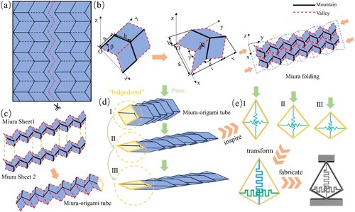
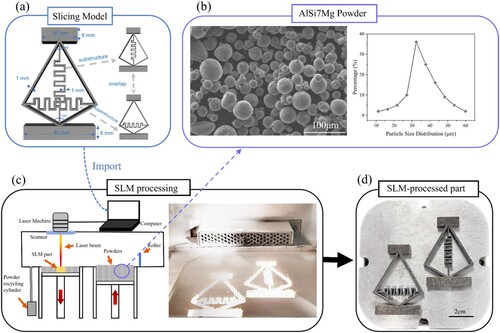
Figure 2. The manufacturing process of the QZS structure: (a) Slicing model; (b) SEM image of the AlSi7Mg powder particles and their size distribution; (c) the schematic illustration of the LPBF process and a photograph of the powder bed during LPBF processing; (d) the LPBF-fabricated components.
(b) illustrates a classical Miura sheet model which can be obtained by repeated arrangement of n Miura sheet units along the x and y directions. By connecting two identical Miura sheets, one obtains the Miura-origami tube ((c)) which can be ‘bulged-out’ ((d)). The corresponding vertical compression motion of the ‘bulged-out’ Miura-origami served as inspiration of an ‘imaginary structure’ which was then transformed to the QZS structure ((e)). The design parameters for the computer-aided (CAD) model of the QZS structure are visualised in (a). The upper and lower quadrilateral frames of the designed QZS structure are 20 and 40 mm wide, respectively, and the structure has a diamond-shaped frame with angles of 60° at the upper end and 120° at the lower end. The frame and designed folds have a thickness of 1 mm. In the work of Wang et al. [Citation40], they systematically investigated the influence of geometric parameters on the mechanical behaviour of origami honeycomb structures. This illustrated the significant sensitivity of the mechanical behaviour of origami materials to characteristic parameters such as length, width, and intersection angles. Through numerical simulations and experimental validation, the angles and frame thickness of the designed structure were ultimately determined. This decision was based on our prior experiments, which showed that samples with a thicknesses less than 1 mm demonstrated poor formability, while samples with a thickness exceeding 1 mm displayed reduced low-frequency absorption capabilities and a narrower low-frequency band gap. Assembling the unit cells yielded the metamaterial illustrated in (a). The weight of the QZS metamaterial consisting of the frame and folds can be neglected compared to the connected lumped mass. The thin-walled metamaterial was designed to suppress the evolution of low-frequency waves within a light-weight part.
2.1.2 LPBF processing
AlSi7Mg was selected as alloy to demonstrate the feasibility of the LPBF-fabrication of the proposed QZS structure, because of its low density and excellent combination of ductility, strength, and corrosion resistance. AlSi7Mg parts show enhanced stability and reliability, particularly in high-performance mechanical systems for vibration damping applications. The SEM image of the powder and the particle size distribution are presented in (b). In the early stages of experimentation, the overall printed formability was suboptimal. By contrast, the concurrent fabrication of two components yielding the QZS structure demonstrated good part accuracy ((c)).
The present QZS structure samples were fabricated in a DiMetal-100H machine. In order to comprehensively investigate the effect of the laser processing parameters on the processing quality, microstructure and mechanical properties of the resulting specimens, the laser energy density η was used [Citation41]:
(7)
(7) where P is the laser power, v is the laser scanning speed, s is the layer thickness and d is the hatching space. In this study, P, s and d were set to the following values of 200 W, 30 and 50 µm, respectively, and v was then varied from 600–1000 mm/s. A monolithic hatching method was used with a fill spacing of 0.08 mm and a 90° orientation rotation between adjacent layers. All the LPBF build jobs were conducted under Ar atmosphere with an oxygen content below 5 ppm. Specimens subjected to uniaxial compressive loading were fabricated at P = 200 W and v = 800 mm/s.
2.2 Characterisation
2.2.1 Simulation
We used Abaqus (Dassault Systemes Simulia Corp, Providence, RI, USA) as finite element method (FEM) software to simulate quasi-static compression tests. To maintain consistency between the experiments and FEM analysis, the lower surface of the finite element model was constrained, while vertical downward displacement loading was applied to the upper surface of the simulated part. The entire process was controlled under quasi-static conditions using energy control. The models were meshed with C3D8 elements and the explicit dynamic solver of ABAQUS was employed to capture the dynamic deformation behaviour. The material properties were set as density ρ = 2680 kg/m³, Young's modulus E = 68.9 GPa, and Poisson's ratio of 0.33 ().
Figure 3. Array model diagrams, meshing, boundary conditions, stress clouds and energy band response clouds inferred from the FEM simulation.
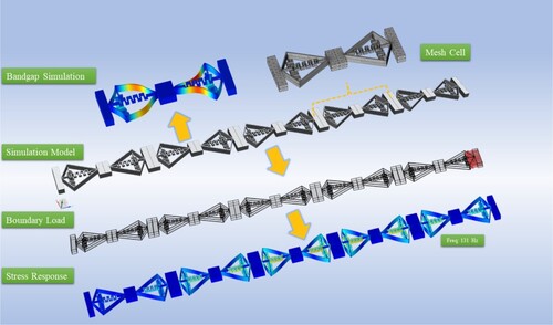
To obtain the energy band harmonic response curves of the QZS structure, we employed the commercial finite element software COMSOL Multiphysics (Comsol Corp, Providence, RI, USA) for numerical simulations. The structural parameters of the specimens utilised in the simulations are provided in (a), and the specimens were systematically arranged, as illustrated in , with a more refined mesh division. Aluminium 3003-H18 in COMSOL was used as the constituent material with a density ρ = 2680 kg/m³, Young's modulus E = 68.9 GPa, and Poisson's ratio of 0.33. During the band gap simulation, we imposed floquet periodic boundary conditions on the unit cell's left and right surfaces, with a periodic vector defined along the vertical direction. The parameter expression ‘solid.refpntz’ was used to generate the longitudinal wave image. For obtaining the harmonic response curve, we applied a load of 0.02 N/ at the top of the model array and set he frequency domain to 1–8000 Hz.
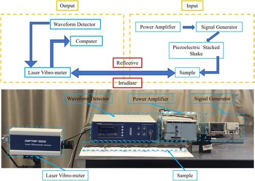
Figure 4. Experimental setup of the QZS structure for determining its harmonic response curves.
In order to obtain the displacement transfer characteristics of the designed model, we calculated the amplitude D and the phase angle φ of the relative displacement between the load and the QZS component by following equation which considered small deflections of the system at its equilibrium position [Citation11,Citation42]. The base excitation was assumed to be , where
is the excitation amplitude and
is the excitation frequency. The nonlinear function
(i = 1, 2) can be expanded via the Taylor series at
, as:
(7)
(7)
(8)
(8)
(9)
(9)
(10)
(10)
Since the fundamental excitation is harmonic, the following expressions are introduced:
(11)
(11)
(12)
(12)
(13)
(13) where D and φ are the amplitude and phase of the system response
, respectively. Thus, we can obtain the relationship between
, D and
:
(14)
(14)
(15)
(15)
Substituting Eqs. (12) and (15) into Eq. (9) and Eq. (11) into Eq. (14), gives:
(16)
(16)
(17)
(17) With, both,
and
equal to 0, the amplitude and phase angle can be inferred. The absolute displacement transfer rate can be given as follows [Citation43]:
(18)
(18) In this work, we approximated the asymmetry stiffness to not affect the accuracy of Eq. (11), though this is not fully correct. The approximated and hence simplified solution yielded, however, acceptable results.
2.2.2 Experimental characterisation
In this study, five replicate trials were performed for each experiment to verify the reproducibility of the data. The density of the LPBF-fabricated components was measured according to Archimedes’ principle. The relative density (ξ) was calculated according to following equation:
(19)
(19) where
is the measured density of the LPBF-fabricated part and
is the theoretical density of AlSi7Mg (2.68
) [Citation44].
For the QZS structure designed in this study, special particular attention must be given to its forming accuracy in terms of the cone angle (θ) and the thickness of thin walls (t). The LPBF-fabricated components were sliced along the building direction (longitudinal section) to carry out optical microscopy (OM) observations along this direction. The key structure parameters were extracted from the OM images utilising the ToupView software.
The surface roughness of the LPBF-fabricated parts was assessed using the Zeiss LSM900 Laser Confocal Microscope. Furthermore, the surface morphology was characterised employing a Regulus8230 scanning electron microscope.
The quasi-static compression tests were carried out using a hydraulic universal testing machine. The phase formation was investigated by X-ray diffraction (XRD, STOE Stadi P, Al Kα1 radiation) of samples with a thickness of about 4 mm, using the continuous scan type with a step size of 0.02°, a scan speed of 0.5 °/min and at 40 kV and 40 mA. All XRD scans were performed in a plane parallel to the building direction. The microstructure was analysed using a field emission scanning electron microscope (FE-SEM; FEI Quanta 650F) and a FEI Tecnai G2 F20 transmission electron microscope (TEM; FEI, Hillsboro, Oregon). The scan step was set to 1 µm, and the grain boundary distribution, grain orientation map and mean dislocation orientation difference distribution maps were determined via electron backscatter diffraction (EBSD, FEI, Hillsboro, Oregon). SEM was also endeavoured to analyse the fracture surface.
The vibration experimental setup and its components are visualised in . The QZS metamaterial is excited by a multilayer piezoelectric actuator through a dSPACE DS1104 system and a white noise signal from a signal generator (AWG5200, Tektronix), which was passed through a signal amplifier (E01.A1, Coremorrow). A laser vibrometer (LV-501, Sunny Optical Intelligence Technology Co) was used to capture the displacement transmission of the metamaterial.
3. Results and discussion
3.1 Geometric accuracy and relative density
Four parameters were used to quantify the geometric accuracy of the QZS structure: frame thickness (), fold thickness (
), top angle (
) and bottom angle (
) (see (a)). (b) displays both angles and T1 as well as T2 as a function of the scanning speed (v). According to the CAD file, the fold thickness and frame thickness are 1.0 and 0.6 mm, respectively. The LPBF-fabricated part showed slightly larger values, which can be mainly ascribed to the surface roughness also resulting from attached partially molten powder particles ((a)). Both thicknesses T1 and T2 gradually decreased with increasing v (600 mm/s to 1000 mm/s). The dimension of
appeared to be manufactured more accurate, since it showed a smaller error of 0.049 mm to 0.008 mm compared to
with an error ranging between 0.144 and 0.06 mm. Both angles
and
gradually increased with faster v from 600 mm/s to 1000 mm/s (
59.67° to 60.29° with 60° as designated angle;
: 119.85° to 120.24° with 120° as designated angle).
Figure 5. (a) Schematic diagram indicating the angles and frame as well as fold thickness of the LPBF-fabricated QZS part; (b) variation of the cone angles, frame thickness and fold thickness of LPBF-fabricated QZS parts dependent on the laser scanning speed.
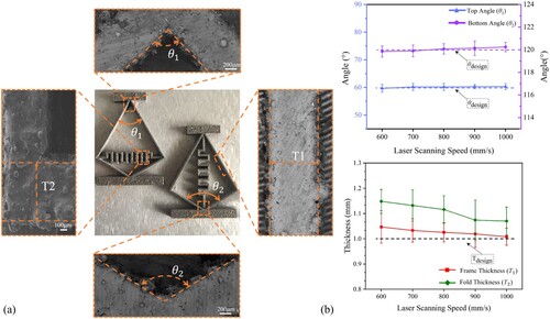
displays the relative density, roughness (Ra) and surface morphDue to the high complexity of the crease area of the QZS structure and the selected scanning strategy, the laser scan duration in this region was longer than for the residual part, so that the fold area is subjected to higher laser energy input. The resulting higher energy input at the fold area led to larger melt pool dimensions and this is the reason for the wall thickness within the fold area of part to be larger than the designated value. The frame of the present QZS structure was fabricated at also varying scanning velocities increasing from 600 mm/s to 1000 mm/s. At the relatively low velocity of 600 mm/s, comparable high-energy density processing conditions are effective, allowing it to reach very high temperatures even beyond the boiling point of the alloy. Then vaporisation might occur [Citation11,Citation42]. Furthermore, a higher volume of previously solidified materiel is remolten, too. Those processing conditions lead to overmelting yielding less accurate part geometry [Citation39]. Therefore, the thickness of the frame is also larger than the designated 1 mm ((b)). The dimensional deviation of the frame and fold can be reduced by decreasing the energy density of the processing conditions by for instance increasing the scanning speed ((b)). Thereby, less wide and deep melt tracks were deposited allowing for LPBF-fabrication of parts at higher dimensional accuracy. Yet, these conditions should allow for full fusion of the deposited melt tracks to layers and good bonding between the layers which generally occurs during their remelting. Otherwise, pores might form adversely affecting the structural stability of the part. The accuracy of the top and bottom angles can be additionally affected by the dynamic behaviour of molten pool. Generally, the melt tends to flow downward under the influence of gravity (Marangoni flow) which could lead to increasing cone angles and affect the low frame thickness [Citation45].
Figure 6. Characteristics of the LPBF-fabricated frame dependent on the scanning speed. (a) Relative density, (b) roughness (Ra); and surface morphology fabricated at increasing scanning speeds of (c) 600 mm/s, (d) 800 mm/s, and (e) 1000 mm/s.
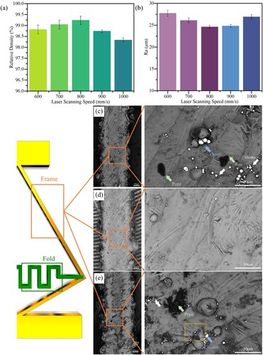
presents the relative density, roughness (Ra) and surface morphology of the manufactured QZS part at varying scanning speeds. The relative density initially increased up to the part fabricated at 800 mm/s with the highest value of 99.26% and then gradually decreased with accelerating velocities down to a relative density of 98.29% at 1000 mm/s. The analysis of the surface morphology corroborates this trend. From the SEM images shown in (c–e) images, one can observe a higher density of small pores on the surface of the top corner of QZS part fabricated at 600 mm/s. By contrast, no pores were visible at the same region for the part fabricated at 800 mm/s which showed a smooth surface. Further increase in v to 1000 mm/s, led to the formation of multiple, large and especially non-spherical pores with a size of about 40 µm in diameter ((e)). It is well known that the densification level of LPBF-fabricated parts with thin-wall structures is sensitive to the applied processing parameters [Citation46–49]. At low v (600 mm/s) a relatively high laser energy density was effective which overheated molten pool. The resulting vaporisation led to the formation of keyhole pores within the molten pool composing the thin-wall structure [Citation50]. At too fast scanning speed, not sufficient energy is provided to the melt pool limiting its size and hence not enabling full fusion of adjacent tracks and layers. Larger pores with irregular shape are the consequence, as was observed at the surface of the part fabricated at 1000 mm/s [Citation51]. Optimum conditions must be selected, since a high densification level is vital for the performance of the LPBF-fabricated QZS parts. Highly porous parts will provide poor tensile properties, might increase the overall stiffness and the natural frequency of the vibration isolation system. Thus, pores will make the vibration isolation system unstable and reduce its efficiency in the low-frequency region which is not desired.
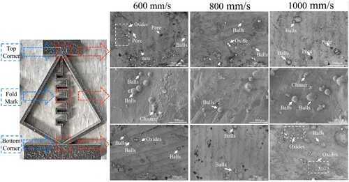
(b) shows the surface roughness at the upper surface of the LPBF-fabricated QZS parts and displays the respective surface morphologies from the top corner, fold mark and bottom corner of the QZS units at increasing scanning speeds. The lowest roughness characterised by an Ra-value of 24.62 µm was obtained at a v of 800 mm/s. It is well known that a rough surface can stem from the balling effect which is related to the surface tension gradients and resulting Marangoni convention within the molten pool [Citation52–54]. In particular, the balling effect is more dominant and more prone to the processing conditions of for the LPBF-fabrication of parts with thin-walled structures parameters than of bulk parts [Citation55]. The present QZS part is composed of multiple thin-walled structures with small-dimension geometric features which only provided lower thermal conductivity to the substrate. Thus heat is extracted slower through the additively manufactured part and in turn radiates stronger into the adjacent powder bed which could result in partial sintering of the powder particles and this adversely affect the density and roughness of the LPBF-fabricated part [Citation56]. This holds especially true for part regions with high geometrical complexity, such as the top corner, fold mark and bottom corner shown in . Owing to the scanning strategy and inertia of the optical bank, the edges of the part tend to be overheated resulting in rounder shape or rephrased enhanced spherification relative to the frame [Citation57]. Building upon the findings of Chen et al. [Citation48,Citation58], strategically elevating the laser scanning speed proves instrumental in significantly improving both surface quality and densification levels. Based on the characterisation of the densification level and surface roughness of the LPBF-fabricated QZS parts, the optimised process parameters were determined as laser power P = 200 W, scanning speed v = 800 mm/s, layer thickness l = 30 µm, and hatching distance h = 50 µm.
Figure 7. Surface morphology of the top corner, bottom corner and fold mark of the QZS part fabricated by LPBF at increasing scanning speeds.
3.2 Microstructure analysis
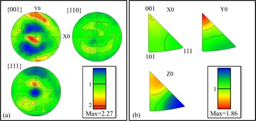
A mostly uniform and isotropic microstructure would be ideal for the present quasi-zero-stiffness structure to efficiently suppress low-frequency longitudinal waves. Since the microstructure of LPBF-fabricated AlSi10Mg parts is determined by the processing conditions and geometry of the part [Citation59,Citation60], three locations of the fold region with highest geometrical complexity of the whole QZS part. The complete part was LPBF-fabricated at identical processing conditions (200 W and 800 mm/s), so that we focused on the influence of the geometry on the microstructure evolution. In order to investigate the microstructural features and potential anisotropy of the three locations of the fold region, EBSD analysis was performed. The grain orientation map of the whole complete fold is displayed in (a), whereby the blue, green, and red colours represent the grain orientations parallel to the <111 > axis, < 101 > axis, and <001 > axis, respectively. (b-d) shows an enlarged view of the grain orientation maps of the three selected regions (a: regions I, II, III) to provide better insight into the anisotropy of the fabricated QZS part. All maps demonstrated that the grain orientation was highly random in all three regions of the fold. The corresponding grain size distribution and average values are shown in (e). The average grain size of the investigated regions was determined to be 12.68 µm, which is smaller than that reported for AlSi10Mg complex thin-walled components reported in the work of He et al. [Citation56]. This small grain size stemmed from the relatively small structure providing large thermal gradient within the molten pool and hence fast heat extraction from the molten pool to the substrate. The resulting high cooling rates led to the solidification of a fine microstructure [Citation32]. shows the pole figures (PF) and inverse pole figure (IPF) inferred from the EBSD maps ((c–e)) of the three selected fold locations. Only a weak <001 > texture was observed along the building direction, since the the solidified microstructure mainly consisted of refined equiaxed grains, owing to the rapid solidification of the thin wall structures. From the EBSD analysis, one can conclude that the microstructure of LPBF-fabricated QZS specimens was highly homogeneous with weak texture which is tantamount to a near-isotropic microstructure. Thus, one can also expect the QZS part to show almost isotropic mechanical properties.
Figure 8. Three representative areas from the fold area are selected for EBSD analysis: (a) EBSD map of the LPBF-fabricated QZS structure at the fold mark; (b-d) enlarged view of three selected part regions; (e) Grain size distribution and average values of the QZS part.
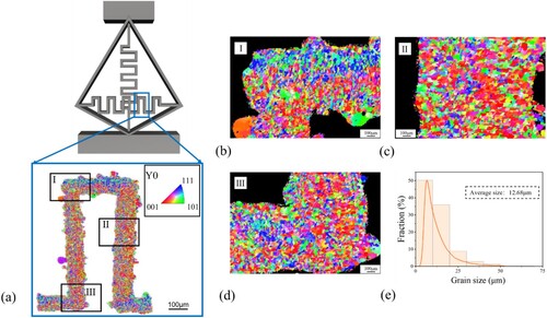
Figure 9. (a) Pole figures (PF) and (b) inverse pole figure (IPF) obtained from the EBSD analysis of the LPBF-fabricated QZS specimen (see ).
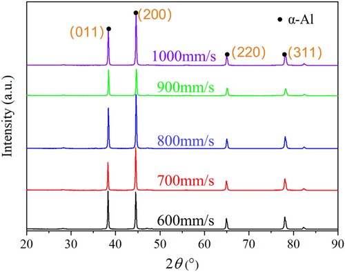
shows XRD patterns of the QZS parts fabricated by LPBF at different scanning speeds. Regardless of the exact scanning speed, all microstructures solely consist of the α-Al phase. We could neither observe any shift of the reflections dependent on the scanning velocity nor precipitation of additional phases. Thus, the applied scanning velocity did not appear to affect the content of solid solutes in the α-Al grains.
Figure 10. XRD patterns of QZS specimens LPBF-fabricated at various scanning speeds.
3.3 Quasi-static compression behaviour
Compression experiments were conducted on five groups of QZS specimens fabricated by LPBF at varying v, and the representative load-displacement curves are depicted in (a). After loading to a displacement of 3.5 mm, all QZS structures demonstrated quasi-zero stiffness behaviour until deformation to a displacement of 5.5 mm. In order to elucidate this quasi-zero stiffness mechanism, FEM simulations were undertaken. Schematic in (b) visualises the corresponding result and in addition to that, images were recorded during compressive testing at the same loading stages to corroborate the FEM results. The horizontal fold of the QZS unit was treated as a horizontal spring during deformation. To be more precise, the horizontal fold and the frame were treated as an integrated structure with negative stiffness, whereas the vertical fold was treated as a vertical spring providing a constant positive stiffness ((c)). (b) displays a sequence of the QZS unit prior to deformation (original state) and at increasing compressive loading. Owing to deformation, the unit is transformed into a new configuration and the corresponding variables of the joints’ translational displacements are shown in (c) (right-hand side). During this deformation process, an averaging method can be used to describe the periodic solutions of the present nonlinear dynamics problem [Citation61]:
(20)
(20) The above equation theoretically verifies the designed structure to have a quasi-zero stiffness property under the designed deformation behaviour. A quasi-static compression simulation was then conducted on the QZS parts to further verify the quasi-zero stiffness mechanism. The simulated von Mises stress maps ((c), top row) within the QZS region showed that the vertical fold was loaded more than the horizontal fold and the frame area at the beginning of the compression process. With increasing displacement, the also increasing stress in the vertical fold was transferred into the horizontal fold. Owing to this load transfer, the stress remained unchanged along the vertical direction within the whole QZS structure and this is the reason why this structure achieved quasi-zero stiffness.
Figure 11. Uniaxial compression texting of the QZS unit: (a) Load-displacement curves of QZS units fabricated at increasing scanning velocity; (b) FEM simulation and experiments describe the deformation of the QZS unit; (c) Simplified schematic diagram highlighting the quasi-zero stiffness.
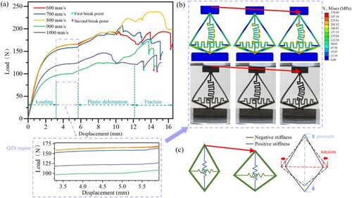
(a) gives a comprehensive description of the compressive behaviour of the LPBF-fabricated QZS component covering stages from initial loading to fracture. Furthermore, specific areas with QZS occurrences are marked. The compressive behaviour of the QZS component can be segmented into four distinct phases: (1) the loading phase, (2) the QZS phase, (3) the plastic deformation phase, and (4) the fracture phase. The loading phase was completed for all QZS units fabricated at different scanning velocity, at the same displacement of about 3.5 mm, but at differing loads. There was no dependence of this load on the processing conditions observed. As previously mentioned, the QZS phase subsequently occurred for all units until a displacement of about 5.5 mm ((a)). The occurrence of the QZS phenomenon in this displacement regime was also substantiated by simulation results ((b), top row) which align well with experimental findings ((b), bottom row). As schematically illustrated in (c), the frame and lateral springs contributed to the negative stiffness, while the longitudinal spring contributed to the positive stiffness during uniaxial compressive loading. We posit that the QZS phenomenon emerged as a consequence of the balancing act between the internal compression and tension within these lateral and longitudinal springs. These unique QZS characteristics manifested at the structural level and were substantiated by dynamic evidence, such as the observing the lowest frequency band gap to align with this specific region, as will be demonstrated later on. As can be seen from the load-displacement curve, the completion of the QZS phase was marked by a load-increase on the QZS units at further deformation. This load increase indicated the plastic deformation phase which ended with the first fracture within the component, whereby the QZS units fabricated at v of 700 and 1000 mm/s were the first ones to fracture. The circular, blue icons indicate this first fracture, which usually occurred at the top corner of the unit frame, as displayed in the inset of (III). Most of those first break points for all LPBF-fabricated QZS parts independent on their processing conditions occurred at a displacement between 13 and 14 mm. By contrast, the load required to cause this first fracture varied a lot for the QZS unit and depended on their LPBF processing conditions. The second fracture (indicated by the diamond, magenta symbol) occurred at a displacement ranging between 14 and 16 mm for most QZS parts and also depended on their LPBF processing parameters. The stress required for the second fracture to occur was very similar to the stress causing the first fracture of the QZS component. It should be noted that, the specimen fabricated at v of 800 mm/s showed no obvious fracture. The load-displacement curves displayed in (a) are representative for the QZS parts fabricated at different scanning velocity.
Figure 12. Comparison between experimental and simulated results of the LPBF-manufactured QZS parts subjected to uniaxial compressive loading. The green arrow marks the loading direction.
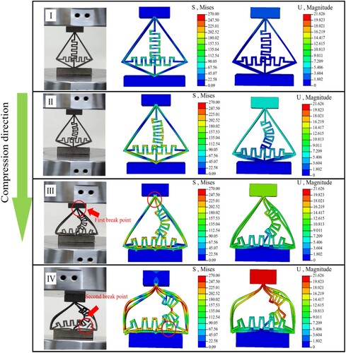
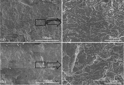
depicts experimentally recorded images and the corresponding FEM simulation results of the von Mises stress and magnitude of the LPBF-manufactured QZS structure during compressive testing at multiple stages with increasing load. As the top rigid compressive plate descends, the stress is induced into the QZS part and it firstly concentrated in the folded area which was also the location of the first fracture. The stress concentration became more distinct with increasing loading which ultimately led to fracture. After the first fracture, a more pronounced stress concentration occurred at the bottom of the transverse fold (marked by the red circle in (IV)) and it caused the second fracture. At first glance, one can perceive that the simulation results showed a high agreement with the experimentally recorded images, since the shape of the deformed folds nicely agreed with the experimentally observed ones. (a,b) show the morphology of the second-fracture site of the QZS structures fabricated at v of 600 and 1000 mm/s, respectively. A high density of dimples was visible on the fracture surface of the LPBF-fabricated QZS structure corroborating the observed, ductile fracture. With the exception of specimens produced at a speed of 800 mm/s, which exhibited cracking only at the second-break sites without complete failure, all other tested samples displayed similar fracture locations and resulting surface morphology.
Figure 13. SEM images of fracture surface of the QZS structures fabricated with at scanning speeds: (a) 600 mm/s; (b) 1000 mm/s.
3.4 Low-frequency vibration isolation property
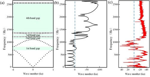
The densification level and mechanical properties of the QZS parts are very important for their low-frequency vibration isolation properties. The surface roughness and key geometrical-structural parameters such as the upper and lower taper angles as well as the thickness of the thin walls of the QZS parts are also important for their anti-vibration performance. According to the work of Limbasiya et al. [Citation62], the order of importance is as follows: densification behaviour > dimensional accuracy (top angle and bottom angle) > dimensional accuracy (frame thickness) > surface roughness. Therefore, the QZS parts processed at v of 800 mm/s were selected for the test low-frequency vibration testing. shows the longitudinal band structure, simulated and experimentally measured transmission curve of the LPBF-fabricated QZS parts. From these results, one can infer that the QZS parts, fabricated with suitable structural parameters for the frame thickness (1 mm), top angle (60°) and bottom angle (120°), can form ultra-wide low-frequency longitudinal band gaps. There were four longitudinal band gaps in the observed frequency range, where the 1st, 2nd the 3rd and the 4th band gaps range from 660 Hz-780, 1120 Hz-1166 Hz, 1167 Hz-1330 Hz and 1420 Hz-2570 Hz, respectively. The experimental results also demonstrated the attenuation of the longitudinal waves over an ultra-wide frequency range. By further analysis of the wave modes at different frequencies, one can find that the wave energy was not only converted to the local resonant along the wave vector, but also formed abundant wave-coupling phenomena including transverse and lateral vibrations to impede the wave propagation. Based on the calculation of the FRF (Frequency Response Function) of the LPBF-fabricated QZS parts ((b)), the attenuation mechanism of the longitudinal waves can be proposed. It is found that the band gap (BG) of the metamaterials consisted of two parts and that the propagation mode of the longitudinal waves within the metamaterials was completely different in the second part of the BG. In the frequency range of the first part, the longitudinal wave was significantly attenuated. The longitudinal wave was then converted into a transverse wave in the frequency range of part 2. At last, the fabricated QZS parts were able to attenuate longitudinal waves in an ultra-wide frequency range exhibiting a quasi-zero stiffness property as demonstrated in (c). In the study conducted by Liu, Li, and Wang [Citation29], scientists enhanced the isotropic elastic characteristics of conventional thin-walled honeycomb structures by integrating strategically designed structural features. The origami metamaterial in this study is also composed through the arrangement and combination of unit cells with quasi-zero stiffness, resulting in a greater variety of wave evolution mechanisms [Citation63].
Figure 14. (a) Longitudinal band gaps of the QZS structure; (b) Simulated transmission curve of the QZS structure; (c) Experimentally obtained transmission curve of the QZS structure.
Literature also reports on configurations that provide nonlinear stiffness by utilising geometric nonlinearities, but these configurations require the introduction of redundant structures. Le and Kwan Ahn [Citation64], for instance, explored a QZS isolation system with two buckled beams serving as negative stiffness elements. Their experimental results showed that the reductions around the resonance of the double-beam system were greater than those around single-beam systems under comparable uniaxial compressive loading. Liu, Peng, and Jin [Citation23] proposed a new class of quasi-zero stiffness (QZS) vibration isolation systems inspired by origami metamaterials for high-performance vibration suppression. In our work, compared to theirs, we observed four bandgaps and a wide range in the low-frequency spectrum up to 3000 Hz. Our structure not only introduced bandgaps within the ultra-low-frequency range but also ensured adequate load-bearing capacity. This can be attributed to the utilisation of laser powder bed fusion (LPBF) as a fabrication method, imparting superior strength, heightened load-bearing capacity, increased stability, and enhanced reliability to the QZS part.
4. Conclusions
Miura-origami tube inspired quasi-zero stiffness metamaterial was prepared by Laser powder bed fusion (LPBF). The effect of laser scanning speed, a key process parameter, on the densification behaviour, geometric accuracy, compressive property and low-frequency vibration isolation property was systematically investigated. Based on the results and discussions, the following important conclusions can be drawn:
The thickness and structural characteristics of thin-walled structures can significantly impact the forming outcomes. Regions with intricate structure are particularly susceptible to pronounced spheroidization effects. Excessive laser scanning speeds can diminish the energy density potentially resulting in incomplete fusion defects. Conversely, overly slow laser scanning speeds can lead to an increase in holes and an exacerbation of the spheroidization effect ultimately leading to reduced formability. In the present case, optimal formability was attained at a laser scanning speed of 800 mm/s and the microstructure of the corresponding QZS specimens fabricated by LPBF, was highly homogeneous and only showed a weak texture being tantamount to isotropic characteristics. Thus, an optimised set of process parameters was identified for LPBF-fabrication of geometrical-complex 1 mm thin-walled structures.
The QZS parts were subjected to uniaxial compressive loading and the experimental results aligned well with the corresponding simulations well. The LPBF-fabricated structure showed quasi-zero stiffness behaviour (QZS) region at displacements between 3.5 mm and 5.5 mm. During compression, the vertical fold was loaded more than the horizontal fold and the frame region. With increasing displacement, tensile forces evolved in the horizontal folds and they gradually counterbalanced the compressive forces in the vertical folds, leading to the emergence of QZS behaviour.
These LPBF-fabricated QZS parts showed four longitudinal band gaps in the observed frequency range with the 1st, 2nd the 3rd and the 4th band gap ranging from 660 Hz-780, 1120 Hz-1166, 1167 Hz-1330 and 1420 Hz-2570 Hz, respectively. The LPBF-fabricated QZS parts demonstrated quasi-zero stiffness characteristics which enabled them to generate low-frequency resonance and to be applied for the absorption of low-frequency longitudinal waves.
This work demonstrated a novel way of controlling longitudinal waves at ultra-low frequencies, and furthermore shed light on how one can steer elastic waves within LPBF-fabricated structures. Such LPBF-fabricated QZS structures can find application in the aerospace sector for energy-absorbing protective structures and in the protection of precision instruments, due to effective vibration damping [Citation65–76].
Disclosure statement
No potential conflict of interest was reported by the author(s).
Data availability statement
All data included in this study are available upon request by contact with the corresponding author.
Additional information
Funding
References
- Zhai Z, Wu L, Jiang H. Mechanical metamaterials based on origami and kirigami. Appl Phys Rev. 2021;8(4). doi:10.1063/5.0051088
- Chen Y, Feng J. Folding of a type of deployable origami structures. Intern J Struct Stabil Dynam. 2012;12(06):1250054), doi:10.1142/S021945541250054X
- Mundilova K. On mathematical folding of curved crease origami: sliding developables and parametrizations of folds into cylinders and cones. Computer-Aided Design. 2019;115:34–41. doi:10.1016/j.cad.2019.05.026
- Sareh P, Chermprayong P, Emmanuelli M, et al. Rotorigami: A rotary origami protective system for robotic rotorcraft. Science Robotics. 2018;3(22):eaah5228), doi:10.1126/scirobotics.aah5228.
- Tao K, Yi H, Yang Y, et al. Miura-origami-inspired electret/triboelectric power generator for wearable energy harvesting with water-proof capability. Microsyst Nanoeng. 2020;6(1):56), doi:10.1038/s41378-020-0163-1
- Turner N, Goodwine B, Sen M. A review of origami applications in mechanical engineering. Proc Instit Mech Eng Part C J Mech Eng Sci. 2016;230(14):2345–2362. doi:10.1177/0954406215597713
- Cai J, Ren Z, Ding Y, et al. Deployment simulation of foldable origami membrane structures. Aerospace Sci Technol. 2017;67:343–353. doi:10.1016/j.ast.2017.04.002
- Sun Z, Yang D, Duan B, et al. Structural design, dynamic analysis, and verification test of a novel double-ring deployable truss for mesh antennas. Mech Mach Theory. 2021;165:104416), doi:10.1016/j.mechmachtheory.2021.104416
- Bai P, Zhu G, Lin Z-H, et al. Integrated multilayered triboelectric nanogenerator for harvesting biomechanical energy from human motions. ACS Nano. 2013;7(4):3713–3719. doi:10.1021/nn4007708
- Guo H, Yeh M-H, Zi Y, et al. Ultralight Cut-paper-based self-charging power unit for self-powered portable electronic and medical systems. ACS Nano. 2017;11(5):4475–4482. doi:10.1021/acsnano.7b00866
- Song Z, Wang X, Lv C, et al. Kirigami-based stretchable lithium-ion batteries. Sci Rep. 2015b;5(1):10988), doi:10.1038/srep10988
- Kuribayashi K, Tsuchiya K, You Z, et al. Self-deployable origami stent grafts as a biomedical application of Ni-rich TiNi shape memory alloy foil. Mater Sci Eng A. 2006;419(1):131–137. doi:10.1016/j.msea.2005.12.016
- Qiu L, Yu Y, Liu Y. Design and analysis of lamina emergent joint (LEJ) based on origami technology and mortise-tenon structure. Mech Mach Theory. 2021;160:104298), doi:10.1016/j.mechmachtheory.2021.104298
- Taylor AJ, Slutzky T, Feuerman L, et al. MR-Conditional SMA-based origami joint. IEEE/ASME Trans Mechatr. 2019;24(2):883–888. doi:10.1109/TMECH.2019.2891993
- Blees MK, Barnard AW, Rose PA, et al. Graphene kirigami. Nature. 2015;524(7564):204–207. doi:10.1038/nature14588
- Jamalimehr A, Mirzajanzadeh M, Akbarzadeh A, et al. Rigidly flat-foldable class of lockable origami-inspired metamaterials with topological stiff states. Nat Commun. 2022;13(1):1816), doi:10.1038/s41467-022-29484-1
- Lv C, Krishnaraju D, Konjevod G, et al. Origami based mechanical metamaterials. Sci Rep. 2014;4(1):5979), doi:10.1038/srep05979
- Xiao K, Liang Z, Zou B, et al. Inverse design of 3D reconfigurable curvilinear modular origami structures using geometric and topological reconstructions. Nat Commun. 2022;13(1):7474), doi:10.1038/s41467-022-35224-2
- Becker C, Bao B, Karnaushenko DD, et al. A new dimension for magnetosensitive e-skins: active matrix integrated micro-origami sensor arrays. Nat Commun. 2022;13(1):2121), doi:10.1038/s41467-022-29802-7
- Ha M, Bermúdez GSC, Liu JAC, et al. Reconfigurable magnetic origami actuators with on-board sensing for guided assembly. Adv Mater. 2021;33(25):2008751), doi:10.1002/adma.202008751
- Mu J, Hou C, Wang H, et al. Origami-inspired active graphene-based paper for programmable instant self-folding walking devices. Sci Adv. n.d.;1(10):e1500533), doi:10.1126/sciadv.1500533
- Jin X, Fang H, Yu X, et al. Reconfigurable origami-inspired window for tunable noise reduction and air ventilation. Build Environ. 2023;227:109802), doi:10.1016/j.buildenv.2022.109802
- Liu S, Peng G, Jin K. Design and characteristics of a novel QZS vibration isolation system with origami-inspired corrector. Nonlinear Dyn. 2021a;106(1):255–277. doi:10.1007/s11071-021-06821-5
- Liu X, Wang C, Zhang Y, et al. Investigation of broadband sound absorption of smart micro-perforated panel (MPP) absorber. Intern J Mech Sci. 2021b;199:106426), doi:10.1016/j.ijmecsci.2021.106426
- Yu X, Fang H, Cui F, et al. Origami-inspired foldable sound barrier designs. J Sound Vib. 2019;442:514–526. doi:10.1016/j.jsv.2018.11.025
- Yasuda H, Yang J. Reentrant origami-based metamaterials with negative poisson's ratio and bistability. Phys Rev Lett 2015;114(18):185502), doi:10.1103/PhysRevLett.114.185502
- Townsend S, Adams R, Robinson M, et al. 3D printed origami honeycombs with tailored out-of-plane energy absorption behavior. Mater Des. 2020;195:108930), doi:10.1016/j.matdes.2020.108930
- Liu K, Tachi T, Paulino GH. Invariant and smooth limit of discrete geometry folded from bistable origami leading to multistable metasurfaces. Nat Commun. 2019;10(1):4238), doi:10.1038/s41467-019-11935-x
- Liu K, Li P, Wang Z. Buckling-regulated origami materials with synergy of deployable and undeployable features. Intern J Mech Sci. 2023;247:108167), doi:10.1016/j.ijmecsci.2023.108167
- Li B, Zhang W, Fu W, et al. Laser powder bed fusion (L-PBF) 3D printing thin overhang walls of permalloy for a modified honeycomb magnetic-shield structure. Thin-Walled Struct. 2023a;182:110185), doi:10.1016/j.tws.2022.110185
- Cai C, Zhou J, Wang K, et al. Quasi-zero-stiffness metamaterial pipe for low-frequency wave attenuation. Eng Struct. 2023;279:115580), doi:10.1016/j.engstruct.2022.115580
- Guo S, Gao R, Tian X, et al. A quasi-zero-stiffness elastic metamaterial for energy absorption and shock attenuation. Eng Struct. 2023;280:115687), doi:10.1016/j.engstruct.2023.115687
- Liu J, Xu S, Wen G, et al. Mechanical behaviour of a creased thin strip. Mech Sci. 2018;9(1):91–102. doi:10.5194/ms-9-91-2018
- Koehly C, Neuberger H, Bühler L. Fabrication of thin-walled fusion blanket components like flow channel inserts by selective laser melting. Fusion Eng Design. 2019;143:171–179. doi:10.1016/j.fusengdes.2019.03.184
- Cai C, Zhou J, Wang K, et al. Metamaterial plate with compliant quasi-zero-stiffness resonators for ultra-low-frequency band gap. J Sound Vib. 2022;540:117297), doi:10.1016/j.jsv.2022.117297
- Lin Q, Zhou J, Wang K, et al. Low-frequency locally resonant band gap of the two-dimensional quasi-zero-stiffness metamaterials. Intern J Mech Sci. 2022;222:107230), doi:10.1016/j.ijmecsci.2022.107230
- Ji JC, Luo Q, Ye K. Vibration control based metamaterials and origami structures: A state-of-the-art review. Mech Syst Signal Process. 2021;161:107945), doi:10.1016/j.ymssp.2021.107945
- Qiang W, Zhang J, Karagiozova D, et al. Quasi-Static energy absorption of miura-Ori metamaterials. JOM. 2021;73(12):4177–4187. doi:10.1007/s11837-021-04939-w
- Lin K, Yuan L, Gu D. Influence of laser parameters and complex structural features on the bio-inspired complex thin-wall structures fabricated by selective laser melting. J Mater Process Technol. 2019;267:34–43. doi:10.1016/j.jmatprotec.2018.12.004
- Wang Z, Yao S, Liu K, et al. Origami embedded honeycomb with three-axial comparable and improved energy absorption performance. Thin-Walled Struct. 2023;193:111295), doi:10.1016/j.tws.2023.111295
- Prashanth K, Scudino G, Maity T, et al. Is the energy density a reliable parameter for materials synthesis by selective laser melting? Mater Res Lett. 2017;5(6):386–390. doi:10.1080/21663831.2017.1299808
- Song C, Yang Y, Liu Y, et al. Study on manufacturing of W-Cu alloy thin wall parts by selective laser melting. Intern J Adv Manufact Technol. 2015a;78(5):885–893. doi:10.1007/s00170-014-6689-3
- Yu G, Gu D, Dai D, et al. Influence of processing parameters on laser penetration depth and melting/re-melting densification during selective laser melting of aluminum alloy. Appl Phys A. 2016;122(10):891), doi:10.1007/s00339-016-0428-6
- Muñiz-Lerma JA, Nommeots-Nomm A, Waters KE, et al. A comprehensive approach to powder feedstock characterization for powder Bed fusion additive manufacturing: A case study on AlSi7Mg. Materials (Basel). 2018;11(12). doi:10.3390/ma11122386
- Yadroitsev I, Krakhmalev P, Yadroitsava I, et al. Energy input effect on morphology and microstructure of selective laser melting single track from metallic powder. J Mater Process Technol. 2013;213(4):606–613. doi:10.1016/j.jmatprotec.2012.11.014
- Guo M, Ming S, Huang J, et al. A comparative study on the microstructures and mechanical properties of Al-10Si-0.5Mg alloys prepared under different conditions. Metals (Basel). 2022a;12(1):142), doi:10.3390/met12010142
- Guo YW, Wei W, Shi W, et al. Selective laser melting of Er modified AlSi7Mg alloy: effect of processing parameters on forming quality, microstructure and mechanical properties. Mater Sci Eng A. 2022b;842:143085), doi:10.1016/j.msea.2022.143085
- Chen H, Gu D, Xiong J, et al. Improving additive manufacturing processability of hard-to-process overhanging structure by selective laser melting. J Mater Process Technol. 2017a;250:99–108. doi:10.1016/j.jmatprotec.2017.06.044
- Chen Z, Wei Z, Wei P, et al. Experimental research on selective laser melting AlSi10Mg alloys: process, densification and performance. J Mater Eng Perform. 2017b;26(12):5897–5905. doi:10.1007/s11665-017-3044-5
- Kosiba K, Kononenko DY, Chernyavsky D, et al. Maximizing vitrification and density of a Zr-based glass-forming alloy processed by laser powder bed fusion. J Alloys Compd. 2023;940:168946), doi:10.1016/j.jallcom.2023.168946
- King WE, Barth HD, Castillo VM, et al. Observation of keyhole-mode laser melting in laser powder-bed fusion additive manufacturing. J Mater Process Technol. 2014;214(12):2915–2925. doi:10.1016/j.jmatprotec.2014.06.005
- Gu D, Shen Y, Fang S, et al. Metallurgical mechanisms in direct laser sintering of Cu–CuSn–CuP mixed powder. J Alloys Compd. 2007;438(1):184–189. doi:10.1016/j.jallcom.2006.08.040
- Simchi A, Asgharzadeh H. Densification and microstructural evaluation during laser sintering of M2 high speed steel powder. Mater Sci Technol. 2004;20(11):1462–1468. doi:10.1179/026708304X3944
- Zhang B, Liao H, Coddet C. Effects of processing parameters on properties of selective laser melting Mg–9%Al powder mixture. Mater Des. 2012;34:753–758. doi:10.1016/j.matdes.2011.06.061
- Gu D, Shen Y. Balling phenomena in direct laser sintering of stainless steel powder: metallurgical mechanisms and control methods. Mater Des. 2009;30(8):2903–2910. doi:10.1016/j.matdes.2009.01.013
- He Z, Liang J, Zhang H, et al. Formability and microstructure of laser powder bed fused AlSi10Mg alloy sheets under various deformation conditions. Mater Charact. 2023;199:112813), doi:10.1016/j.matchar.2023.112813
- Abarca Manuel J, Darabi R, Cesar de Sa J, et al. Multi-scale modeling for prediction of residual stress and distortion in Ti–6Al–4V semi-circular thin-walled parts additively manufactured by laser powder bed fusion (LPBF). Thin-Walled Struct. 2023;182:110151), doi:10.1016/j.tws.2022.110151
- Chen H, Kosiba K, Suryanarayana C, et al. Feedstock preparation, microstructures and mechanical properties for laser-based additive manufacturing of steel matrix composites. Intern Mater Rev. 2023;68(8):1192–1244. doi:10.1080/09506608.2023.2258664
- Li W, Li S, Liu J, et al. Effect of heat treatment on AlSi10Mg alloy fabricated by selective laser melting: microstructure evolution, mechanical properties and fracture mechanism. Mater Sci Eng A. 2016;663:116–125. doi:10.1016/j.msea.2016.03.088
- Yadroitsev I, Yadroitsava I. Evaluation of residual stress in stainless steel 316L and Ti6Al4V samples produced by selective laser melting. Virtual Phys Prototyp. 2015;10(2):67–76. doi:10.1080/17452759.2015.1026045
- Han H, Sorokin V, Tang L, et al. A nonlinear vibration isolator with quasi-zero-stiffness inspired by miura-origami tube. Nonlinear Dyn. 2021;105(2):1313–1325. doi:10.1007/s11071-021-06650-6
- Limbasiya N, Jain A, Soni H, et al. A comprehensive review on the effect of process parameters and post-process treatments on microstructure and mechanical properties of selective laser melting of AlSi10Mg. J Mater Res Technol. 2022;21:1141–1176. doi:10.1016/j.jmrt.2022.09.092
- Li Z-N, Yuan B, Wang Y-Z, et al. Diode behavior and nonreciprocal transmission in nonlinear elastic wave metamaterial. Mech Mater. 2019;133:85–101. doi:10.1016/j.mechmat.2019.03.010
- Le TD, Kwan Ahn K. Experimental investigation of a vibration isolation system using negative stiffness structure. Intern J Mech Sci. 2013;70:99–112. doi:10.1016/j.ijmecsci.2013.02.009
- Dai D, Gu D. Tailoring surface quality through mass and momentum transfer modeling using a volume of fluid method in selective laser melting of TiC/AlSi10Mg powder. Intern J Mach Tools Manuf. 2015;88:95–107. doi:10.1016/j.ijmachtools.2014.09.010
- Gu D, Hagedorn Y-C, Meiners W, et al. Nanocrystalline TiC reinforced Ti matrix bulk-form nanocomposites by selective laser melting (SLM): densification, growth mechanism and wear behavior. Compos Sci Technol. 2011;71(13):1612–1620. doi:10.1016/j.compscitech.2011.07.010
- Huang X, Liu X, Hua H. On the characteristics of an ultra-low frequency nonlinear isolator using sliding beam as negative stiffness. J Mech Sci Technol. 2014;28(3):813–822. doi:10.1007/s12206-013-1205-5
- Li Z, Mukai K, Zeze M, et al. Determination of the surface tension of liquid stainless steel. J Mater Sci. 2005;40(9):2191–2195. doi:10.1007/s10853-005-1931-x
- Li Z, Li X, Zhonggang W, et al. Multifunctional sound-absorbing and mechanical metamaterials via a decoupled mechanism design approach. Mater Horiz. 2023b;10(1):75–87. doi:10.1039/D2MH00977C
- Liu Y, Yang Y, Mai S, et al. Investigation into spatter behavior during selective laser melting of AISI 316L stainless steel powder. Mater Des. 2015;87:797–806. doi:10.1016/j.matdes.2015.08.086
- Nayak SK, Mishra SK, Paul CP, et al. Effect of energy density on laser powder bed fusion built single tracks and thin wall structures with 100 µm preplaced powder layer thickness. Optics Laser Technol. 2020;125:106016), doi:10.1016/j.optlastec.2019.106016
- Olakanmi EO, Cochrane RF, Dalgarno KW. A review on selective laser sintering/melting (SLS/SLM) of aluminium alloy powders: processing, microstructure, and properties. Prog Mater Sci. 2015;74:401–477. doi:10.1016/j.pmatsci.2015.03.002
- Sutton AT, Kriewall CS, Leu MC, et al. Powder characterisation techniques and effects of powder characteristics on part properties in powder-bed fusion processes. Virtual Phys Prototyp. 2017;12(1):3–29. doi:10.1080/17452759.2016.1250605
- Wang L-z, Wang S, Wu J-j. Experimental investigation on densification behavior and surface roughness of AlSi10Mg powders produced by selective laser melting. Optics Laser Technol. 2017;96:88–96. doi:10.1016/j.optlastec.2017.05.006
- Yuan L, Gu D, Lin K, et al. Influence of structural features on processability, microstructures, chemical compositions, and hardness of selective laser melted complex thin-walled components. Intern J Adv Manufact Technol. 2020;109(5):1643–1654. doi:10.1007/s00170-020-05773-1
- Zhang J, Yuan W, Song B, et al. Towards understanding metallurgical defect formation of selective laser melted wrought aluminum alloys. Adv Powder Mater. 2022;1(4):100035), doi:10.1016/j.apmate.2022.100035