
 ?Mathematical formulae have been encoded as MathML and are displayed in this HTML version using MathJax in order to improve their display. Uncheck the box to turn MathJax off. This feature requires Javascript. Click on a formula to zoom.
ABSTRACT
In multi-robot cooperative wire and arc additive manufacturing (MRC-WAAM) systems, allocating and scheduling deposition tasks is necessary. The challenge comes from the factorial computational complexity when optimising robot time, workload, and deposition order. This work presents a novel method, ‘top k%’. The main idea is to iteratively assign k% amount of paths from a warehouse to the robot having the least workload until all paths are set. A collision-free deposition process is scheduled by checking the overlapping conditions of robot swap areas. Both simulative testing and actual depositions were conducted to validate the applicability and effectiveness of the method. The results indicated that the ‘top k%’ method can facilitate the equality of robot workload and enhance the adjacency of paths. The top k% method outperforms the existing solutions concerning a reduction of turns and start-arc points, which improves the forming quality of MRC-WAAM.
Abbreviations
| AM | = | additive manufacturing |
| CAD | = | computer-aided design |
| DED | = | directed-energy deposition |
| DT | = | deposition task |
| EB-DED | = | electron beam-directed energy deposition |
| EWL | = | equality of workload |
| GMA | = | gas metal arc |
| GOA | = | goodness of adjacency |
| GTA | = | gas tungsten arc |
| LDED | = | laser-directed energy deposition |
| MRC | = | multi-robot cooperation |
| PA | = | plasma arc |
| PW | = | path warehouse |
| RoS | = | radius of safety |
| SA | = | swept area |
| SEM | = | schedule-efficiency metric |
| WP | = | work period |
1. Introduction
1.1. Background and motivation
Additive manufacturing (AM) fabricates solid parts directly from CAD models by gradually melting, fusing, sintering, or extruding raw materials layer-by-layer [Citation1]. As aerospace, energy, mining, and shipping industries advance, there is a discernible inclination towards part consolidation in design, which aims to reduce the total number of parts in the final product by designing and fabricating parts with large-scale geometry and complex morphology [Citation2,Citation3]. For this reason, AM has been widely adopted in the current practice, and large-scale metal parts have been identified as a promising research direction [Citation4].
Directed-energy deposition (DED) refers to a category of AM technology that involves the feeding of powder or wire to an energetic source to form a melted layer on a substrate, such as laser-directed energy deposition (LDED), electron beam-directed energy deposition (EB-DED), and wire and arc additive manufacturing (WAAM). With the merits of being cost-competitive and time-efficient, WAAM is employed for fabricating parts with large-scale geometries and moderate structural complexity [Citation5]. The approximate deposition rates can be up to 500 cm3/h [Citation6]. In addition, WAAM can be easily integrated with an industrial robot, which facilitates the freedom of fabrication and eliminates the size restriction of the parts to be built [Citation7]. However, a meter-scale part still takes weeks or more by a single actuation system. The long-term deposition process necessitates a high level of system performance stability to ensure the production of defect-free parts.
To enhance manufacturing efficiency, multi-robot cooperative (MRC-) WAAM has been promoted, which requires multiple robotic AM systems to work coordinatively [Citation8]. A fundamental step is to properly allocate and schedule robot deposition paths for every layer before the actual deposition process can be executed. The challenge comes from the factorial computational complexity when assigning the deposition paths for robots and scheduling the deposition process with an optimal consideration of time, workload, and safety. Driven by the challenge, this paper aims to develop an algorithmic solution that facilitates the MRC-WAAM process planning.
1.2. Literature study
WAAM offers the flexibility to utilise a wide variety of metal materials. The latest reports also focused on combining wire and powder as the fed material [Citation9]. Wire-based deposition is incomparable with the powder counterparts when customising the material compositions at different positions of a large-scale part [Citation10]. However, wire metals are usually much more cost-effective and safe in utilisation and storage [Citation11]. The heat source of WAAM can be either gas metal arc (GMA)-based, gas tungsten arc (GTA)-based, or plasma arc (PA)-based. Concerning GTA-AM and PA-AM, the relative orientation of material feeding influences shape-forming quality. They are suited for long and straight (or large-curvature) deposition paths rather than zig-zag paths where the motion direction of deposition frequently changes [Citation12]. GMA-AM employs a weld gun where the wire is fed out from its centre, dramatically reducing the complexity of path planning and process optimisation [Citation13]. This characteristic facilitates the integration of GMA power supply to robotic systems and promotes the proliferation over recent decades. Many large-scale parts have been successfully produced using robotic GMA-AM systems, such as ship propellers [Citation14], propeller brackets [Citation15], rocket shells [Citation16], excavator arms [Citation17], and multi-directional pipe joints [Citation18].
WAAM considers every slice morphology for process planning that determines the deposition paths and weld parameters like other AM alternatives. Parameter adjustments are made to improve surface roughness and dimensional precision of the deposited components according to the specific situation at different positions, such as material, structure, and heat dissipation field [Citation19,Citation20]. Usually, a single bead deposited on a flat substrate is considered the basic element for process planning, and its cross-sectional profile has been represented by various models, such as parabola, arc, and cosine models [Citation21]. According to the literature, there is an optimal step-over distance between adjacent parallel beads, e.g. 0.667w, where w refers to the width of a single bead [Citation22]. Many path planning methods have been developed, such as raster, zig-zag, contour, spiral, continuous, medial axis transformation, modular path planning, and hybrid [Citation23]. Therefore, slice morphology, cross-sectional profile model, step-over distance model, and path planning methods are jointly considered when determining the specific deposition parameters.
Despite extensive research focusing on the deposit quality and mechanical properties, the deposition rate of AM is a significant concern [Citation24]. The deposition rate of conventional WAAM can be up to 4 kg/hour in steel, while tons of material need to be deposited. In addition, the inter-layer idle time also plays an essential role in shaping the thermal behaviour, microstructure, and stress state of the deposit [Citation25]. Concerning the deposition time and inter-layer idle time, the total production time of a meter-level part can be 1–2 months. Many innovative robot-carried devices have been developed to enhance productivity. He et al. [Citation26] implemented a device that enables a single robot to carry five weld guns for deposition. However, the motion of individual weld guns depends on the movement of the robot, which increases the complexity of process planning and programming. Reisgen et al. [Citation27] developed a deposition head for multi-wire WAAM, increasing the deposition rate and facilitating the customisation of feed material. Han et al. [Citation28] developed an auxiliary-wire GMA-AM approach for improving the deposition rate of material while maintaining the weld current at a relatively low value.
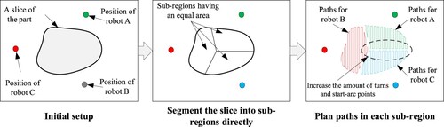
Utilising multiple independent robots to enhance AM productivity is another solution. Issues related to robot placement and obstacle avoidance have been identified as significant research challenges [Citation29]. Zhang et al. [Citation30] developed a framework for producing large-scale concrete parts using a team of mobile robots. However, the deposition path for each robot was defined independently. Bhatt et al. [Citation31] proposed a mechanism for optimising the positions of robots in an MRC-WAAM system. Manoharan et al. [Citation32] presented a model decomposition method for plastic parts. A 3D part was decomposed into intersected sub-volumes to enhance the bonding strength between deposits of different robots. Shen et al. [Citation33] proposed a path generation algorithm by directly partitioning a slice into regions with an equilibrium area. In the studies mentioned above, the process planning and optimisation are achieved by (i) segmenting the slice of a part into sub-regions and (ii) ordering robots to follow paths generated in the sub-regions, respectively. The segmentation mechanism works for AM of non-metal parts, whereas its applicability for metal AM is questioned. Directly segmenting a slice can increase turns and start-arc points, as illustrated by . These areas are prone to defects commonly observed in metal parts, such as porosity, lack of fusion, and slag inclusion [Citation34].
Figure 1. Path planning for MRC-AM by directly segmenting a slice into sub-regions.
An important issue for process planning of a multi-robot system is the task allocation and scheduling problem. Heuristic mechanisms are commonly applied in literature. For instance, Panchu et al. [Citation35] developed a genetic algorithm-based approach for allocating foraging tasks for robots concerning precedence constraints. Li et al. [Citation36] proposed an improved genetic algorithm to solve the task assignment problem for a multi-robot search and recon application. Suslova et al. [Citation37] presented a layered iterative framework for multi-robot task allocation with time window and ordering constraints. Poudel et al. [Citation38] proposed a modified genetic algorithm for MRC-AM by decomposing the volume of a part into chunks and managing the deposition order of different chunks for collision avoidance.
It can be concluded from the literature that the existing heuristic solutions treated the task allocation and scheduling problems independently since the space constraint was not the primary issue in the tested applications, e.g. foraging, search, and recon. When considering collision avoidance, most heuristic methods are time-consuming and can hardly be applied for MRC-WAAM, where hundreds of paths are involved. In addition, the work range of every robot in an MRC-WAAM system is limited and cannot completely cover a large-scale part. The dissimilarity of robot ability may raise the complexity and difficulty of computation further. Therefore, there is a lack of mechanism from the literature that supports task allocation and scheduling for MRC-WAAM.
1.3. Objective and content
The objective of this paper is to provide an algorithmic solution for the allocation and scheduling of MRC-WAAM after slicing. Accordingly, a novel computational method is proposed based on a ‘top k%’ principle. The idea is to distribute the k% amount of reachable paths to a robot with the least workload. Our research hypothesises that the ‘top k%’ method can maintain the adjacency of distributed paths for every robot, while reducing computational complexity regarding task distribution and scheduling. The structure of this paper is arranged as follows: Section 2 introduces the fundamental principle and workflow of the ‘top k%’ algorithm. Section 3 centres on the implementation work. Section 4 focuses on the validation aspect, in which experimental results and discussions are presented.
2. The ‘top k%’ method
2.1. The strategy for allocating paths in a layer
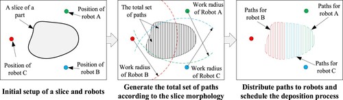
The strategy applied by this paper is presented in . According to the morphology of the slice, a total set of deposition paths should be generated. Before the paths are allocated to robots, the reachable paths of every robot are specified concerning the position of paths and the working radius of robots. Accordingly, the generation of the total set of paths should ensure that every path can be reachable by at least one robot. Otherwise, there will be one path or more that cannot be completed by the MRC-WAAM system unless a path segmentation operation is conducted. For path allocation, particular objectives can be targeted, e.g. the workload of robots should be as equal as possible to maximise the total work efficiency. After this step, paths for individual robots are determined. Then, the deposition order and time of the allocated paths can be scheduled to avoid potential collision among robots, and between the robots and the deposited part. After everything is ready, robot programmes can be generated, delivered to robots, and executed by robots.
Figure 2. Overall workflow for allocating deposition paths for MRC-WAAM.
It’s worth mentioning that this paper was striving for a general method, where only the path allocation and scheduling problems are focused. It means that elementary paths should be generated in the total set before the presented method can be applied. As a primary research, this paper only considers a flat layer deposited by multiple robots with a downward direction of deposition, neglecting issues related to the rotation of the layer and repositioning of robots. For simplification, raster paths will be generated in the total set for demonstration and validation.
2.2. Mathematical formulation of the problem
The path allocation and scheduling issue of MRC-WAAM can be formulated into the following mathematical model: Assuming there are paths, noted as
, and
robots, noted as
. The execution cost matrix
can be stated in the form of a matrix as follows:
(1)
(1) where
refers to the cost of the ith path executed by the jth robot.
The length of paths can be distinguished by the set, . The deposition velocities of the paths are noted as
, which are associated with planned deposition parameters. Then, the individual deposition time for each path can be calculated by
/
. Assuming a Boolean matrix
is used to indicate if path
can be entirely done by robot
or not, which is noted by:
(2)
(2) The elements of
are calculated by:
(3)
(3) Assuming a Boolean matrix
is used to present if path
is assigned to robot
or not, that is:
(4)
(4) Since the deposition time of a path is much longer than the time it takes for a robot to move among paths, the travel time from one path to another is not considered for computing the total work time. Then, the total working time
of robot
can be computed by the following formula:
(5)
(5) The primary objective of path allocation for MRC-WAAM is to minimise the total work time of all robots, which is defined by the work time of the last-to-finish robot. Accordingly, the objective can be written as:
(6)
(6) Because multiple paths can be assigned to a robot, and every path can only be assigned to a robot once, the following constraints are generated:
(7)
(7)
(8)
(8) Formula (6) is equivalence to a situation in which the work times of all robots are equal. Then, the equality of workload (EWL) is defined:
(9)
(9) where
refers to the average deposition time of all robots,
is the standard deviation of the same. If all robots are assigned the same amount of workload, then
will be zero, and EWL will be 100%. If the standard deviation exceeds the average value, EWL becomes a negative value.
For WAAM, the adjacency of paths followed by a robot is crucial to the quality of forming and collision avoidance. The goodness of adjacency (GOA) of paths distributed to robots can be evaluated by the following indicator:
(10)
(10) where
= 1, if path
and its neighbouring paths are distributed to the same robot;
= 0, if path
and its neighbouring paths are distributed to different robots. Accordingly,
ranges within [0,1].
Considering both Formula (9) and Formula (10), the path allocation is a multi-objective optimisation issue. Since both EWL and GOA are dimensionless, the objective function of optimisation can be written as follows:
(11)
(11) where
is the weighting factor.
According to the mathematical model, the path allocation problem is a typical combination issue containing cases in total. The scheduling problem is a permutation issue, and the number is calculated as:
(12)
(12) where
is the number of paths assigned to the robot
, subject to:
(13)
(13) and
indicates that a path can be deposited from any end to another.
Concerning the scheduling problem of robot work, the deposition order of paths assigned to a robot can be noted by a sequence of paths, that is , where
refers to the running number of paths assigned to robots in the sequence, the total number of paths q of robot
can be calculated by:
(14)
(14) The objective of scheduling is to determine the sequences
,
, …
for robots such that the weld guns or robot linkages do not collide. When robot
moves along an assigned path, the swept volume of the robot can be noted by
. Accordingly, the following constraint is defined for collision prevention:
(15)
(15) where
is the swept volume of robot
,
. Formula (15) means that the intersection of swept volumes of any two robots should be empty. This method developed in this paper is revised from the work presented by McPherson et al. [Citation39].
Formula (15) only defines the constraint, while there might be multiple solutions beyond the achievement of Formula (15). The deposition plan determined for an MRC-WAAM system should keep all robots away from each other as much as possible to avoid potential collisions. For this reason, the objective function for the scheduling problem can be defined as:
(16)
(16) where
is the distance between
and
.
2.3. Mechanism of the top k% method for assignment
For MRC-WAAM, hundreds of deposition paths are typically determined for a large-scale part. If heuristic methods are applied, either exponent or factorial complexity may lead to failures. The challenge is to decrease the computational complexity of the assignment and scheduling problems. Driven by this ideation, the top k% method was developed, and its mechanism is depicted in .
Figure 3. The computational mechanism for assigning paths to multiple robots.
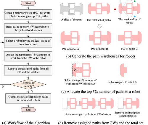
Concerning a slice of a part, a total set of paths should be generated before the assignment algorithm can be executed. An individual path warehouse (PW) should be created for robots by checking the work radiuses of the robots and the positions of paths, as shown in (b). Every PW stores paths that the robot can complete. The paths stored in a PW are then ranked according to the path-robot distances, which are calculated by:
(17)
(17) where
is the position of robot
,
is the gravity centre of path
. Accordingly,
refers to the linear distance between
and
.
Then, iterative operations are performed. In every iteration, a robot having the least total time of work is selected, the totaled work time of paths in its PW, i.e. , are calculated. k% amount of work from the unassigned paths is allocated to the robot, as shown in (c). The work amount assigned at a time, i.e.
, can be calculated by:
(18)
(18) Since paths are ranked according to the path-robot distances, this step ensures that a group of the nearest paths is assigned at a time. Due to the reason that the deposition time of paths are different, the nearest paths are considered for assignment until the sum of their work time is greater than
. After an assignment, the assigned paths should be removed from all PWs and the total set, as shown in (d). The next iteration starts until the total set becomes an empty set.
It can be seen from the workflow that the mechanism handles a group of paths at a time rather than treating paths individually. Using the top k% method, the count of assignments is independent of the number of paths in the total set and the robot number. One benefit is that the count of assignments can be reduced as much as possible. For this reason, the method is able to handle complex situations, no matter how great the number of paths to be assigned is. Another benefit of the method is that the adjacency of assigned paths for a robot can be enhanced. It is realised by ranking paths according to the path-robot distances and assigning paths from the top of the list. These operations reduce the occurrence of path interlacing, which means adjacent paths are assigned to different robots, which may cause potential collisions of robots during actual depositions. It’s worth mentioning that the sum of work time of unassigned paths in PW changes after every assignment, making the decreases as the iteration progresses. Then, the workload assigned to robots decreases, and the work time of robots becomes equal, which ensures the realisation of the objective function.
2.3. Mechanism of the process scheduling
Deposition tasks (DTs) should be generated according to the assigned paths to schedule the deposition process of multiple robots. A DT refers to a series of positions that a robot is ordered to complete the deposition paths. A DT can be directly translated to an executable robot programme. The mechanism for generating DTs is illustrated in .
Figure 4. Generation of deposition tasks.
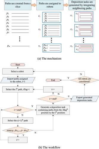
According to Formula (9), the computational complexity of scheduling correlates with the number of elements to be handled. If adjacent paths are jointly treated, the complexity of scheduling can be reduced significantly. One more benefit of the proposed top k% method is that the paths assigned to a robot are naturally adjacent. As shown in (a), neighbouring paths assigned to a robot could form a deposition task by connecting endpoints of neighbouring paths in the context of the raster path-planning method. This coincides with a requirement of WAAM that discrete paths should be integrated into longer paths to reduce the number of starting and distinguishing points of the arc.
The algorithm workflow for generating DTs from assigned paths is shown in (b). Since paths are ranked according to the path-robot distances, the adjacency among paths is checked from the top of the individual list of robots one after another. In every iteration, the algorithm checks if the distance from any endpoints of a selected path to those of the next is smaller than a threshold value, where refers to the distances among endpoints of path
and path
;
refers to a threshold value, usually determined according to the surface finish requirement of the WAAMed part. It can be seen from the mechanism that the scheduling issue is reduced from Formula (12) to the following:
(19)
(19) where
is the number of DTs assigned to robot
, subject to:
(20)
(20) where
is the total number of DTs. After generating DTs,
will be much less than
, guaranteeing reduced computational complexity.
After DTs are determined, the order of execution by robots should be scheduled before robot programmes can be generated. The problem is to minutely predict the distances between any two robots to check if a collision might happen. However, calculating the spaces of a multi-robot cooperation scenario step by step is time-consuming. Furthermore, although Formula (19) has reduced the number of cases for computation, finding a collision-free arrangement out of the totaled combinations can hardly be achieved without repetitive checking of the distances among robots. A computational mechanism was developed to solve the issue by segmenting DTs that can accelerate the collision-checking process.
According to Formula (15), the swept volume of robots should be considered time-wise when the robots are assumed to execute DTs. However, the number of DTs might differ, and the DTs might be diverse in length and duration. These facts imply that the swept volume of DTs cannot be directly compared concerning space and time. In this work, the DTs are segmented to ensure the compared DTs have a standard work period (WP). The basic principle for defining a WP is to find a period in which all robots work simultaneously. The process can be illustrated using the example shown in , in which DTs of robots are arranged successively in time. The start time of the first WP is the start time point of the entire deposition process (i.e. t = 0), while that of the rest of the WPs is the end time point of the prior WP. The end time point of a WP is the start time point of the subsequent DT executed by any robot, while that of the last WP is the end time point of the entire deposition process. As shown by the example in and WPs are generated. It is worth mentioning that the segmentation operation is merely employed to define WPs for collision checking rather than create new DTs. In addition, the end time point of the deposition process of each robot might be different. The last WP continues until the last-to-finish robot stops.
Figure 5. Defining the work periods (WPs) of a deposition plan.
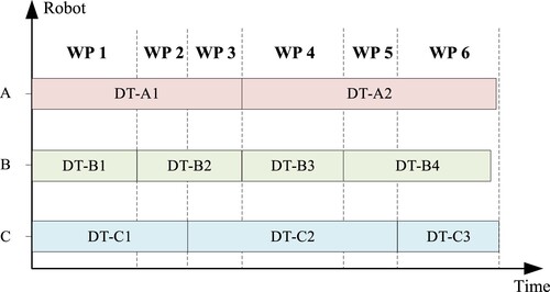
Figure 6. The mechanism for checking the swept area of robots within a WP.
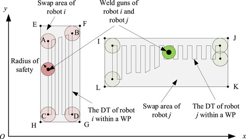
After WPs are defined, the spatial relations among robots should be predicted to ensure a collision-free deposition. The Formula (12) was a strict constraint, where the computation of the swept volume of all robots in a time-wise manner is time-consuming. For this reason, this paper developed a simplified method for collision prediction, as illustrated by . In the case of MRC-WAAM, the robots are working on the same deposition layer with a flat-position gesture. The swept volume of a robotic arm for a WP can be projected to a plane that is parallel to the substrate, forming a swept area (SA). The top k% method ensures that all assigned paths are as close to the belonging robots as possible. Consequently, a circle positioned at the centre of the weld gun with a radius of safety (RoS) can be used to represent the swept area of the first joint of robot at a given position, while the swept area of the rest joints can be ignored.
Since DTs are defined in XOY coordinates, the area defined by the max & min values of the paths (e.g. the quadrangle ABCD) can be extended to form a rectangle (e.g. the rectangle EFGH) when the RoS is taken into consideration, forming the SA of the robot. After the SAs of multiple robots within a WP are generated, the collision prediction problem of multiple 3D volumes can be reduced to an overlapping checking problem of various polygons. There are numerous on-the-shelf algorithms for finding the overlap of polygons, which facilitates implementation work and enhances computational efficiency. Furthermore, since the developed mechanism does not need to consider the start and end of a DT, the element in the Formula (19) can be omitted.
Based on the concepts mentioned above, the workflow for scheduling a deposition plan for an MRC-WAAM system is presented in . After importing the DTs developed for robots, alternative deposition plans are generated by finding the total permutations concerning different orders of DTs. For every deposition plan, the algorithm should check whether the SAs of robots in the WPs overlap. If the SAs do not overlap within a WP, then the robots will not collide during the WP. In this situation, the algorithm finds the nearest distance among all SAs and saves the value in a nearest distance set, which is used later on to obtain the globally optimal solution. After all deposition plans are checked, the maximum value of the closest distance set represents a case in which all robots work with the furthest distances. Then, the objective function defined by Formula (16) is achieved.
Figure 7. The workflow for scheduling a deposition plan for the MRC-WAAM system.
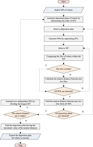
Although the presented solution works for most situations, exceptions still exist where the nearest distance sets are empty. The exception indicates a condition that all SAs overlap concerning the currently generated DTs of robots, which is caused by the relatively low number of DTs and WPs for comparison. Accordingly, the algorithm executes an iterative operation after dividing the longest DT into two shorter DTs. Since a DT is defined by integrating deposition paths, the division operation can be achieved by finding the middle position of the DT in length.
3. Implementation
For experimental validation in practice, a test platform was implemented. shows a schematic diagram and the actual prototype of the test platform. The platform consists of three YASKAWA AR1730 industrial 6-axis robots, three sets of MEGMEET Artsen Plus 500Q weld power supply, a host computer, and a work platform. The robots were called Robot A, B, and C, respectively. The robot and the weld power supply were controlled by a robot control cabinet. The host computer owned an AMD Ryzen 7 5800H processor with a Radeon Graphic card (3.20 GHz). The proposed allocation and scheduling algorithms were implemented by MATLAB R2021b.
Figure 8. The implemented test platform.
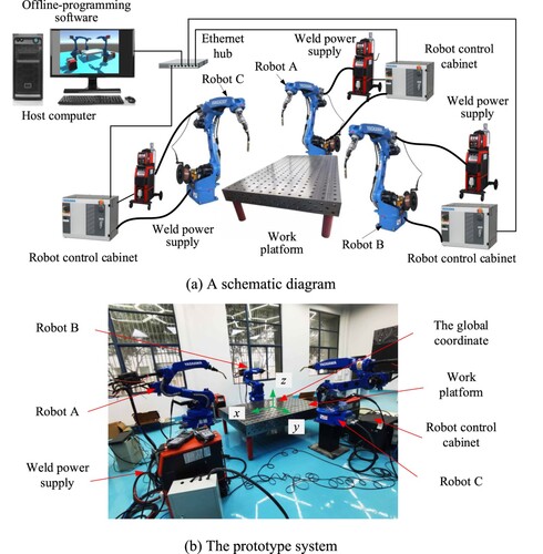
A global coordinate was defined at the centre of the work platform to enable coordinated depositions of multiple robots. The centre of the to-be-deposited part was located at the origin of the global coordinate. All robot programmes were generated referencing the global coordinate. The spatial relationship between robots and the centre of the part is presented in . In the host computer, an offline programming software was developed that is able to validate the effectiveness of a generated robot programme. The offline programming software was also used to check whether the robots would collide according to the path scheduling result. The software programme contained a module that can translate a deposition plan to a robot executable programme, e.g. the*.jbi format file for the YASKAWA robots. After generating robot programmes, the host computer sent the programmes to robot control cabinets through Ethernet communication. During the actual deposition process, the starting of a robot programme was controlled by the host computer according to the scheduling results of deposition plans.
Figure 9. Spatial relationship among robots and the centre of part.
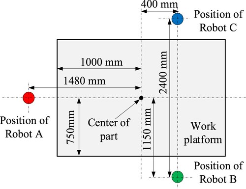
For experiments, the material of the fed-wire was ER70S-6, while that of the substrate was Q235B. The chemical compositions of the materials are presented in . The diameter of the fed wire was 1.2 mm. The dimensions of the substrate were 600 mm × 400 mm × 10 mm (length × width × height). The shielding gas was 95% Ar and 5% CO2 with a flow rate of 20 L/min. Specific parameters applied for experiments are shown in . It is worth mentioning that all the beads are designed with the same deposition parameters, which indicates that the work time of robots depends on the length of the paths. In addition, the step-over distance was set as 2/3 of the width of a single bead.
Table 1. Chemical composition of substrate and fed-wire (wt.%).
Table 2. Parameters applied for experimental validation.
4. Experimental validations
The allocation and scheduling mechanisms were validated through two interconnected phases of experiments. On the one hand, models of four large-scale parts having varied lengths and numbers of deposition paths were applied to validate the feasibility of the implemented algorithms. On the other hand, a model was selected for real-life depositions to validate its applicability in practice. Details of the two phases are introduced in Section 4.1 and Section 4.2, respectively.
4.1. Validation of the allocation mechanism
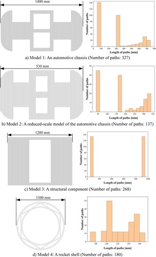
The models dedicated to the testing are presented in . The models were designed with different validation objectives. Model 1 was an unmanned automotive chassis, while Model 2 was a reduced-scale model. A comparison between the results can show how the algorithm performs with models having a similar statistical distribution of path lengths since the objective function of path allocation is to balance the workload of robots. Model 3 was designed for extreme testing where only two types of deposition paths were concerned: long and short paths. A binary distribution can be observed from the statistical distribution of path lengths. Model 4 was a simplified model of a rocket shell. Since none robot could complete all paths independently, the inner and outer circular paths were segmented, forming another extreme situation where an approximate mean distribution can be seen. Model 3 and Model 4 can be compared to test whether the algorithm is sensitive to the distribution of path lengths.
Figure 10. The models used for validation.
Regarding the morphology of the slices, raster paths were generated using the parameters presented in . The positions of robots were set according to those presented in , while the linear distances between paths and robots were calculated and used for ranking paths in the individual PW of robots. The proposed top k% method allocates the nearest k% deposition paths to a robot with the least workload. Accordingly, the performance of the mechanism strongly depends on the value of k, which determines the amount of work allocated every time. For this reason, the influence of k was first tested regarding the designed models, and the EWL and GOA results are shown in . Generally, the EWLs of models 1, 2, and 4 decrease as the value of k increases. The difference is that the EWLs of models 1 and 2 fluctuate when k is lower than 40, whereas the EWL of model 4 decreases monotonously. Another interesting phenomenon is that the EWL of model 3 starts with a relatively low value and fluctuates when k is lower than 35.
Figure 11. The influence of k on the algorithm performance.
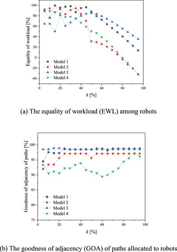
The reason can be identified from the length distribution of the designed models. Model 1 and 2 have short paths at their centre, which are far away from the positions of the robots. It implies that the short paths will be placed at the bottom of the ‘path-robot’ distance list and allocated to robots at the final computation stage. Since long paths count more weight on the total workload of a robot, distributing short paths after assigning long paths can facilitate realising equilibrium in workload. However, if the anterior allocations resulted in a significant distinction of workload among robots, the distribution of the rest of the short paths would be powerless. For instance, the sum of path length assigned to a robot at a time may exceed 1/n of the sum of path length of the total set, leading to a failure situation in the work time of robots that cannot be balanced by whatever way of assignment in the subsequent iterations. In contrast, the length of paths in Model 4 follows a mean distribution. For this reason, the less workload is distributed to a robot at a time, the higher EWL will be achieved.
The results presented in (b) indicate a different phenomenon. The top k% method generally ensures over 89% of GOA concerning all models. In particular, the algorithm shows a fair performance in maintaining the allocated paths contiguous for the cases of models 1, 2, and 3 when the value of k is 25 and greater. This implies that the smaller the number of paths allocated to a robot at a time, the worse the path adjacency will be. It contradicts the result of the EWL, where a smaller value of k is expected. In addition, the GOA of the fourth model fluctuated between 89% and 96%. This is because the paths in the fourth model are dispersed to each other in nature. Therefore, it can be stated that the value of k has a significant influence on the performance of the allocation algorithm. A relatively small value of k enhances the equality of the workload of robots, whereas it impedes the adjacency of paths. A great k makes the workload of robots diverse and maintains suitable adjacency of paths. As Formula (11) suggests, both EWL and GOA should be considered in the objective function. Therefore, a moderate value of k should be determined.
The results of path allocation using the proposed method at k = 35 are presented in , in which the weighting factor of the objective function was 0.5, and model 2 reached its optimum value of 0.96. Since the existing methods in the literature cannot be directly used, another algorithm was also implemented for the purpose of comparison. In the second algorithm, paths are allocated to robots individually. In every iteration, the closest path is assigned to the robot with the least workload. The results of individual allocation concerning the four models are shown in . After using Formula (9) and Formula (10), the EWL, GOA, and computation time of the two developed methods are presented in .
Figure 12. The path allocation results using the proposed top k% method.
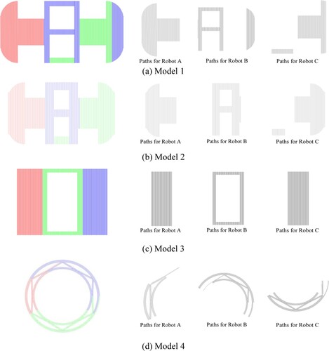
Figure 13. The results of assigning paths individually.
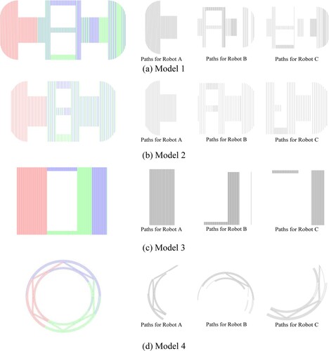
Table 3. Comparison between the two developed approaches.
It can be seen from the results that the computation time spent by the top k% method is much less than that of the individual allocation strategy while maintaining a relatively steady performance (within 27 ms) as the path number changes. In addition, the top k% method enables a high value of GOA and a competitive EWL. According to Formula (11), the top k% method outperforms individual allocation concerning the overall objective of optimisation (i.e. Ω). It can also be seen that the overall performance of the individual allocation strategy fluctuates concerning different slices. Because the top k% method can allocate paths that are naturally adjacent to each other, making it independent of the path number. In contrast, allocating paths one by one neglects the spatial relationship among paths, resulting in a situation where paths belonging to different robots may intersect. This can be observed from the results of (a, b). In these cases, scheduling the actual deposition process will be extremely difficult to avoid potential collisions among robots. Therefore, the results of the comparison approved the feasibility of the implemented algorithm. The top k% method improved both the equality of the workload of robots and the adjacency of paths allocated to individual robots.
4.2. Validation of the scheduling mechanism
According to the proposed scheduling mechanism, the deposition process of model 2 was planned. The radius of safety (RoS) was specified as 50 mm, which means that the distance between the centres of any two weld guns cannot be smaller than 100 mm. The Gantt diagram developed for the actual deposition process is shown in , and the results of deposition tasks generation and scheduling are presented in . It can be seen that 10 deposition tasks (DTs) are generated for the three robots, while the deposition process was decomposed into 6 work periods (WPs) for checking the distances among swap areas (SAs) of weld guns. The algorithm generated 2, 3, and 5 DTs for the robots, respectively. It’s worth mentioning that the motion speed between two successive DTs of a robot was set as 12 mm/s, making the idle time neglectable.
Figure 14. The Gantt diagram of the deposition process.
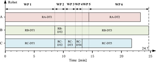
Figure 15. Results of deposition tasks generation and scheduling.
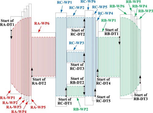
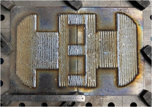
The distances among the SAs over the WPs are shown in . All values are greater than or equal to zero, which means that the safety of weld guns can be ensured. After confirming the safety of multiple robot cooperation, the generated robot programmes were set to the robots for actual experiments. The appearance of the deposited slice is shown in . It can be seen that the material formation was reasonably fair, which proves the implemented algorithm was effective.
Figure 16. The distances among the swap areas over the work periods.
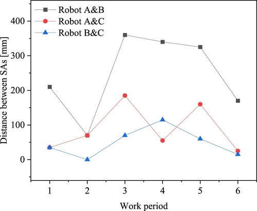
Figure 17. The appearance of the deposited slice.
For evaluating the efficiency of multi-robot cooperation, a schedule-efficiency metric (SEM) was defined as:
(21)
(21) where
indicates the theoretical average time achieved by the multi-robot system, while
refers to the actual time spent for manufacturing. For the reason that
refers to an optimal situation in which the time spent by all robots are equal, the SEM indicates how much the actually spend time is close to that in the optimal situation. For instance, if
, SEM will be 100%, which means that the optimal situation is achieved.
The total deposition time for fabricating the slice using a single robot is 4083 s if the idle time spent moving among paths is neglected. In the performed experiment, the actual deposition time was 1478 s. Accordingly, the SEM of the test result is 92.1%. Although the result is acceptable for MRC-WAAM, the reason for the distinction between the and the
is two-folded. On the one hand, the objective function presented in Formula (11) jointly considers the equality of workload (EWL) and the goodness of adjacency (GOA), whereas Formula (21) only addresses the equality of robot work. The optimum solution has to ensure collision-free depositions in the path scheduling step. For this reason, the paths were not equally allocated to all robots. On the other hand, the actual deposition process contains idle periods spent by robots for moving among DTs, which resulted in the waste of the exact work time.
The validation result was further compared with those calculated using the current state-of-the-art methods. shows the planning results of Model 2 using the method proposed by Bhatt et al. [Citation31], while shows those developed by the solution of Shen et al. [Citation33]. A comparison of quantitative evaluation results concerning the three methods is shown in . Bhatt’s method directly segments the slice into three pieces with the same area. It can be seen from that many turns are generated around the area segmentation lines. The increase of turns, i.e. 183 turns, causes defects at the beads-overlapping positions, e.g. inclusions and infusions. In addition, the interference of weld guns cannot be avoided entirely concerning the allocation results, which confines the application of Bhatt’s method for complex parts.
Figure 18. The deposition plan scheduled using the strategy proposed by Bhatt et al. [Citation31].
![Figure 18. The deposition plan scheduled using the strategy proposed by Bhatt et al. [Citation31].](/cms/asset/2ea54b7f-5b17-414a-b73b-922d1579dc5a/nvpp_a_2300680_f0018_oc.jpg)
Figure 19. The deposition plan scheduled using the strategy proposed by Shen et al. [Citation33].
![Figure 19. The deposition plan scheduled using the strategy proposed by Shen et al. [Citation33].](/cms/asset/78da1fee-d355-4d0a-ac1f-41f913e44a98/nvpp_a_2300680_f0019_oc.jpg)
Table 4. Comparison of the proposed method with the state-of-the-art.
Since Shen’s method introduces the concept of interference area, the safety of robots over the fabrication process can be ensured. However, the segmentation of interference areas from the slice of the part increases a significant number of turns around the segmentation lines of the interference areas, which resulted in 293 turns in total. On the other hand, Shen’s method scheduled the deposition process by mismatching the robot deposition process of the interference areas. For this reason, Robot B has to interrupt the deposition tasks when Robot A finishes the interference area of RA. This principle should also be applied to Robot C for working within the interference area of RA. Accordingly, two additional start-arc points are generated. The increase of both turns and start-arc points produces more defects in the final part. In contrast, the method of this paper only generates 127 turns, which are located at the part borders. Post-milling operations can be easily applied to remove potential defects at the turns. In addition, our method allocates parts to balance the total work time of robots rather than their work area, which enhances the efficiency of work, and a higher value of SEM is obtained.
4.3. Discussions
Based on the validation work, the feasibility and applicability of the proposed algorithms were approved. It can be seen that our method is different from brute-force methods and heuristic methods in nature. The novelty of this work can be highlighted based on the observed phenomenon. From the scientific point of view, the ‘top k%’ method paves a new and practical way for solving the large-scale unbalanced assignment and scheduling problem. On the one hand, paths are ranked according to the path-robot distances, which enables assigning a group of adjacent paths at a time. This coincides with the objective of the assignment for WAAM, namely, paths assigned to a robot should be as close as possible. On the other hand, paths assigned in every iteration naturally form a basic unit for scheduling, which significantly reduces the number of elements to be arranged for optimisation. From the technological point of view, the ‘top k%’ method is superior to the existing direct segmentation methods since it can reduce the number of turns and start-arc points, which prevents the formation of defects for the MRC-WAAM.
According to the problem definition, factorial computational complexity has been identified as the research challenge in finding an optimal solution using brute-force methods. Since the ‘top k%’ method distributes k% amount of path in every iteration, it performed complexity of time in the worst case concerning the path allocation problem, where m refers to the path number. The worst case is when there is no intersection of each robot's workspace and the number of paths per robot is
. This case has the highest number of algorithmic loops. The number of loops to assign paths to each robot converges to
, so the time complexity is obtained as
. Concerning the scheduling problem, the computational complexity depends on the number of DTs rather than the number of paths, meaning that the scale of the scheduling problem was significantly reduced. In the case study, the path numbers for robots were 37, 50, and 50, respectively, before the generation of DTs. It means that the optimal situation has to be found from approximately 10192 situations according to Formula (12). Using the proposed algorithm, the number of situation is reduced to 1440 according to Formula (19), which is far less than before generating DTs.
The research hypothesis assumed that the ‘top k%’ method can be integrated with the existing path generation methods. Based on the conducted validation work, it can be seen that raster paths fit the method very well. The path allocation and scheduling mechanism are independent of the path morphology, which means that other types of paths can also be applied, such as zig-zag, contour, medial axis transformation (MAT), or hybrid methods. However, the principle for ranking different types of paths and scheduling the order of deposition should be further investigated. For instance, the contour and MAT methods generate closed-loop paths that conform to the slice shape. Ranking the closed-loop paths is another technical issue since their gravity centres coincide. Additionally, since the swap areas of the robot working could overlap, the collision-free scheduling algorithm proposed in this paper becomes invalid. These limitations of the proposed method deserve further research attention when using the ‘top k%’ method in practice. In addition, this paper only focuses on a simple scenario in which the deposition parameters of all robots are the same. The top k% method can be further applied in more complex scenarios, such as depositions with varying speeds by a team of mobile robots. A sufficient validation of the work deserves further research attention and investigation.
5. Conclusions
This paper introduces a ‘top k%’ method, which facilitates the path allocation and scheduling for multi-robot coordinated wire and arc additive manufacturing (MRC-WAAM) of large-scale metal parts. The primary ideation of the mechanism is to iteratively assign k% amount of paths from a path warehouse to a robot having the least workload until all paths are set. The effectiveness of the mechanism was demonstrated through both simulation testing and actual experiments. Conclusions can be drawn as follows:
(i) As validated by the research, the nearest k% amount of paths assigned every time are naturally adjacent to each other, which enhances the adjacency of paths allocated to each robot.
(ii) In the conducted case study, the schedule-efficiency metric of the deposition plan reaches 92.1%, which confirms that the proposed method can maintain the equality of robot workload.
(iii) As implied by the experimental results, the top k% method outperforms the direct segmentation methods concerning the reduction of the number of turns and start-arc points, which enhances the forming quality of MRC-WAAM.
(iv) From the computational point of view, the ‘the top k%’ method reduces the computational complexity of both the allocation and scheduling problems. It has the potential for solving related issues in dynamic scenarios where runtime adaption of multi-robot cooperation might be required.
Author contributions
Dr. Yongzhe Li conceived the theory, designed experiments, and wrote the paper. Mr. Lingyi Meng contributed to the implementation and programming. Mr. Mingliang Li was responsible for experimentation and data analysis. Mr. Yijun Zhou initialised and supervised the research. Dr. Xiaochao Liu and Dr. Xinlei Li helped with conceptualisation. Prof. Guangjun Zhang contributed to conceptual validation.
All authors have read and agreed to the published version of the manuscript.
Disclosure statement
No potential conflict of interest was reported by the author(s).
Data availability statement
The data presented in this study are available on request from the corresponding author.
Additional information
Funding
References
- Lewandowski JJ, Seifi M. Metal additive manufacturing: a review of mechanical properties. Ann Rev Mater Res. 2016;46:151–186. https://www.annualreviews.org/doi/abs/10.1146annurev-matsci-070115-032024.
- Najmon JC, Raeisi S, Tovar A. 2 - Review of additive manufacturing technologies and applications in the aerospace industry. Addit Manuf Aerosp Ind. 2019: 7–31. doi:10.1016/B978-0-12-814062-8.00002-9
- Altıparmak SC, Yardley VA, Shi Z, et al. Challenges in additive manufacturing of high-strength aluminium alloys and current developments in hybrid additive manufacturing. Int J Lightweight Mater Manuf. 2021;4(2):246–261. doi:10.1016/j.ijlmm.2020.12.004
- DebRoy T, Wei HL, Zuback JS, et al. Additive manufacturing of metallic components – Process, structure and properties. Prog Mater Sci. 2018;92:112–224. doi:10.1016/j.pmatsci.2017.10.001. A. Alessandro, L. Adrian, L. Erica, F. Alessandro, Laser Directed Energy Deposition of Bulk 316L Stainless Steel, Lasers Manuf. Mater. Process. 7 (2020) 426-448, https://doi.org/10.1007/s40516-020-00128-w.
- Garcia-Colomo A, Wood D, Martina F, et al. A comparison framework to support the selection of the best additive manufacturing process for specific aerospace applications. Int J Rapid Manuf. 2020;9(3):194–211. doi:10.1504/IJRAPIDM.2020.10019230
- Lin Z, Song K, Yu X. A review on wire and arc additive manufacturing of titanium alloy. J Manuf Process. 2021;70:24–45. doi:10.1016/j.jmapro.2021.08.018
- Thomas L, Dylan R, Ehsan R, et al. Large-scale metal additive manufacturing: a holistic review of the state of the art and challenges. Int Mater Rev. 2022;67(4):410–459. doi:10.1080/09506608.2021.1971427
- Babu SS, Lonnie LJ, Peter WH, Dehoff R. Workshop report on additive manufacturing for large-scale metal components - development and deployment of metal big-area-additive-manufacturing (Large-Scale Metals AM) System, Technical Report, United States, 2016. doi:10.2172/1325459
- Sun J, Yu H, Zeng D, et al. Wire–powder–arc additive manufacturing: a viable strategy to fabricate carbide ceramic/aluminum alloy multi-material structures. Addit Manuf. 2022;51; doi:10.1016/j.addma.2022.102637
- Alessandro A, Adrian L, Erica L, et al. Laser directed energy deposition of bulk 316L stainless steel. Lasers Manuf Mater Process. 2020;7:426–448. doi:10.1007/s40516-020-00128-w
- Moghazi S, Wolfe T, Ivey D, et al. Plasma transfer arc additive manufacturing of 17-4 PH: assessment of defects. Int J Adv Manuf Technol. 2020;108:2301–2313. https://api.semanticscholar.org/CorpusID:253674910.
- Yu Y, Xiong J, Chen Y, et al. Process stability control of corner structures in robotic gas tungsten arc additive manufacturing via arc sensing. J Manuf Process. 2023;101:156–170. doi:10.1016/j.jmapro.2023.05.076
- Xiong J, Wen C. Arc plasma, droplet, and forming behaviors in bypass wire arc-directed energy deposition. Addit Manuf. 2023;70:103558. doi:10.1016/j.addma.2023.103558
- Ziółkowski M, Dyl T. Possible applications of additive manufacturing technologies in shipbuilding: a review. Machines. 2020;8(4):84. doi:10.3390/machines8040084
- He T, Yu S, Shi Y, et al. Forming and mechanical properties of wire arc additive manufacture for marine propeller bracket. J Manuf Process. 2020;52:96–105. doi:10.1016/j.jmapro.2020.01.053
- Li Y, Su C, Zhu J. Comprehensive review of wire arc additive manufacturing: hardware system, physical process, monitoring, property characterization, application and future prospects. Results Eng. 2022;13:100330. doi:10.1016/j.rineng.2021.100330
- Greer C, Nycz A, Noakes M, et al. Introduction to the design rules for metal big area additive manufacturing. Addit Manuf. 2019;27:159–166. doi:10.1016/j.addma.2019.02.016
- Dai Y, Yu S, Shi Y, et al. Wire and arc additive manufacture of high-building multi-directional pipe joint. Int J Adv Manuf Technol. 2018;96:2389–2396. doi:10.1007/s00170-018-1742-2
- Li Y, Huang X, Horváth I, et al. GMAW-based additive manufacturing of inclined multi-layer multi-bead parts with flat-position deposition. J Mater Process Technol. 2018;262:359–371. doi:10.1016/j.jmatprotec.2018.07.01
- Jafari D, Vaneker THJ, Gibson I. Wire and arc additive manufacturing: opportunities and challenges to control the quality and accuracy of manufactured parts. Mater Des. 2021;202:109471. doi:10.1016/j.matdes.2021.109471
- Xiong J, Zhang G, Gao H, et al. Modeling of bead section profile and overlapping beads with experimental validation for robotic GMAW-based rapid manufacturing. Robot Comput Integr Manuf. 2013;29:417–423. doi:10.1016/j.rcim.2012.09.011
- Li Y, Sun Y, Han Q, et al. Enhanced beads overlapping model for wire and arc additive manufacturing of multi-layer multi-bead metallic parts. J Mater Process Technol. 2018;252:838–848. doi:10.1016/j.jmatprotec.2017.10.017
- Ding D, Pan Z, Cuiuri D, et al. Wire-feed additive manufacturing of metal components: technologies, developments and future interests. Int J Adv Manuf Technol. 2015;81:465–481. doi:10.1007/s00170-015-7077-3
- Babu SS, Lonnie LJ, Peter WH, Dehoff R. Workshop report on additive manufacturing for large-scale metal components - development and deployment of metal big-area-additive-manufacturing (Large-Scale Metals AM) System, Technical Report, United States, 2016. doi:10.2172/1325459
- Lei Y, Xiong J, Li R. Effect of inter layer idle time on thermal behavior for multi-layer single-pass thin-walled parts in GMAW-based additive manufacturing. Int J Adv Manuf Technol. 2018;96:1355–1365. doi:10.1007/s00170-018-1699-1
- He T, Yu S, Huang A, et al. Path planning and forming of wire multi-arc additive collaborative manufacture for marine propeller bracket. J Manuf Process. 2021;68:1191–1201. doi:10.1016/j.jmapro.2021.06.028
- Reisgen U, Sharma R, Oster L. Plasma multiwire technology with alternating wire feed for tailor-made material properties in wire and arc additive manufacturing. Metals (Basel). 2019;9(7):745. doi:10.3390/met9070745
- Han Q, Gao J, Han C, et al. Experimental investigation on improving the deposition rate of gas metal arc-based additive manufacturing by auxiliary wire feeding method. Weld World. 2021;65:35–45. doi:10.1007/s40194-020-00994-0
- Urhal P, Weightman A, Diver C, et al. Robot assisted additive manufacturing: a review. Robot Comput-Integr Manuf. 2019;59:335–345. doi:10.1016/j.rcim.2019.05.005
- Zhang X, Li M, Lim JH, et al. Large-scale 3D printing by a team of mobile robots. Autom Constr. 2018;95:98–106. doi:10.1016/j.autcon.2018.08.004
- Bhatt PM, Nycz A, Gupta SK. Optimizing multi-robot placements for wire arc additive manufacturing, in: Proceedings of the 2022 International Conference on Robotics and Automation (ICRA), 2022, pp. 7942–7948.
- M. Manoharan, A.N. Shridhar, V.Y. Vinod, S. Kumaraguru, A novel volume decomposition methodology for multi-robots collaborative additive manufacturing, in: Proceedings of the 2020 IEEE 4th Conference on Information & Communication Technology (CICT), 2020, pp. 1-6.
- Shen H, Pan L, Qian J. Research on large-scale additive manufacturing based on multi-robot collaboration technology. Addit Manuf. 2019;30:100906. doi:10.1016/j.addma.2019.100906
- Ding D, Pan Z, Cuiuri D, et al. Adaptive path planning for wire-feed additive manufacturing using medial axis transformation. J Clean Prod. 2016;133:942–952. doi:10.1016/j.jclepro.2016.06.036
- Panchu KP, Rajmohan M, Sundar R, et al. Multi-objective optimisation of multi-robot task allocation with precedence constraints. Def Sci J. 2018;68:175–182. doi:10.14429/dsj.68.11187
- Li S, Xu X, Zuo L. Task assignment of multi-robot systems based on improved genetic algorithms. Proceedings of the 2015 IEEE International Conference on Mechatronics and Automation (ICMA), 2015, pp. 1430–101435.
- Suslova E, Fazli P. Multi-robot task allocation with time window and ordering constraints. Proceedings of the 2020 IEEE/RSJ International Conference on Intelligent Robots and Systems (IROS), 2020, pp. 6909–6916.
- Poudel L, Zhou W, Sha Z. Resource-constrained scheduling for multi-robot cooperative three-dimensional printing. J Mech Des. 2021;143:072002. doi:10.1115/1.4050380
- McPherson J, Zhou W. A chunk-based slicer for cooperative 3D printing. Rapid Prototyp J. 2018;24(9):1436–1446. doi:10.1108/RPJ-07-2017-0150