
 ?Mathematical formulae have been encoded as MathML and are displayed in this HTML version using MathJax in order to improve their display. Uncheck the box to turn MathJax off. This feature requires Javascript. Click on a formula to zoom.
ABSTRACT
By using Invar 36 alloy as the constituent material, a series of multi-functional metamaterials, integrating low coefficient of thermal expansion (CTE) and programmable Poisson’s ratio (PR), were originally designed and additively manufactured by laser powder bed fusion (PBF-LB). The densification, relative density, microstructures, CTE and PR were systematically characterised and analysed by experiments and numerical modelling. Specifically, the fabricated metamaterials demonstrate uniform microstructures, resulting in isotropic low CTEs ranging from 1.79 to 1.85 ppm/°C. Besides, the designed metamaterials achieve PR tuning in the range of −0.54∼+0.58, which is close to the theoretical predictions, confirming the PR programmability. The underlying mechanism is disclosed that the variable θ1 dominates the transverse deformation behaviour of the metamaterial, achieving programmable PR. Summarily, these metamaterials achieve the integration of the low CTE and programmable PR, and provide a wider operating temperature range and superior mechanical performances than polymer-based multi-functional metamaterials, exhibiting a broader application prospect.
1. Introduction
The concept of metamaterial was originally proposed by Veselago [Citation1] and was defined as artificially designed materials that exhibit extraordinary physical properties or functions not inherent in natural materials [Citation2–5]. Whereas rapidly developing additive manufacturing processes enable the integrated formation of complex geometric components, enhancing the design flexibility and expediting the development of metamaterials. As a result, multi-functional metamaterials, a type of metamaterials that exclusively exhibit multiple exceptional functions under different external stimulus or conditions, was developed and widely applied in engineering applications, such as biomedicine, acoustic devices, catalytic scaffolds, fuel cells, satellites, aircrafts and heat exchangers, etc. [Citation6–13].
Particularly, in aerospace engineering, the mechanical- and temperature-sensitive devices, typically represented by the space deployable structures, are inevitably subjected to a coupled loading of both temperature and mechanical loads. Therefore, the high dimensional stability is crucial to ensure a precise deployment and retraction actions in such harsh service environments. Fortunately, a type of multi-functional metamaterials, exactly integrating programmable both coefficient of thermal expansion (CTE) and Poisson's ratio (PR), making it ideal for fulfilling that by simultaneously achieving the low or purposed CTE and PR. However, despite the high demand for engineering applications, there are only a limited number of works that have reported these multi-functional metamaterials, which could be classified into bi-material [Citation14–25] and tri-material [Citation26–28] metamaterials. In detail, based on the bi-material layout, a variety of two-dimensional (2D) and three-dimensional (3D) metamaterials were designed, and the integrated programmability of CTE and PR was demonstrated by rationally altering the geometrical parameters [Citation14–25]. On the other hand, the tri-material metamaterials, integrating programmable CTE and PR, were also designed [Citation26–28], and the underlying mechanisms relating the geometric parameters to the programmability were identified.
Notably, the above-mentioned limited works integrated the programmable CTE and PR, strongly depending on introducing the exclusive multi-material layouts, which indeed gives rise to a huge challenge in fabricating it efficiently by using the traditional manufacturing processes. Indeed, the multi-material additive manufacturing processes are currently capable of maturely fabricating the multiple polymer-based metamaterials, while it still remains the challenge for the fabrication of metal-based multi-material metamaterials. However, polymer-based multi-material metamaterials typically fall short in meeting the demands of engineering applications, primarily owing to their limited operating temperature range and weak mechanical performances.
In order to achieve both low CTE and PR, an alternative approach of multi-material metamaterials, is to turned the view to Invar 36 alloy, a face-centred cubic Fe-Ni alloy, especially with the Ni content of approximately 36.0%, and attracts considerable attention and applications for its unique function of extremely low CTE (≤2.0 ppm/°C) below Curie temperature (230°C) [Citation29–33]. Moreover, it possesses significantly superior mechanical performances compared with the conventional polymers. Additionally, considering its good weldability and high laser absorptivity, the additive manufacturing process, such as laser powder bed fusion (PBF-LB), provides a promising alternative to fabricate complex Invar 36 alloy components, even cellular or architecture structures [Citation34,Citation35]. In fact, it should be noted that the reported works [Citation36–42] usually focus on the PBF-LB process and performance of bulk Invar 36 alloy. However, the design of cellular metamaterials by using Invar 36 alloy as the constituent material, so as to integrate multiple functions, especially low CTE and PR, is not reported, except that only the mechanical performances of Invar 36 alloy triply periodic minimal surface (TPMS) cellular structures, fabricated by PBF-LB, were explored by He et al. [Citation43]. It can be optimistically expected that by rationally designing and additively manufacturing the cellular metamaterials, purposely using Invar 36 alloy as the constituent material, it will provide a promising alternative to achieving the multi-functional integration of low CTE and programmable, especially low PR, fulfilling the urgent requirement from both mechanical- and temperature-sensitive devices.
Accordingly, here, as a continuous of our previous works about the PBF-LB process and mechanical performances of bulk Invar 36 alloy [Citation32,Citation34,Citation36], a series of multi-functional metamaterials with their constituent material as Invar 36 alloy, were originally designed and additively manufactured by PBF-LB, so as to integrate low CTE and programmable PR. As the important basis, the microstructures, densifications and relative densities were experimentally characterised. Subsequently, the CTE and PR tests coupled with the numerical modelling, namely, finite element analysis (FEA) were conducted to validate the multiple functions. Moreover, the deformation behaviour and mechanism of these metamaterials during the loading process were carefully identified.
2. Multi-functional metamaterials
2.1. Design strategy
Here, Invar 36 alloy is designed as the constituent material of the multi-functional metamaterials, thus these metamaterials inherently integrate one unique function of low CTE (≤2.0 ppm/°C). Furthermore, as illustrated in , the fundamental unit of target metamaterials is exactly the triangle arrow (TA) [Citation14]. In detail, as given in (a), Li, θi, t and b define the in-plane length, angle, width and out-plane thickness, respectively. Notably, in order to avoid the geometric interference, the design constraints should follow: 45°<θ1 < 90°, 0°<θ2<θ1, θ3 = 45°, L1cosθ1< L2cosθ2, t/L1 < 0.1. Further, following the concept of hierarchical design, category A unit cell (AS) with vertex-connected configuration and category B unit cell (BS) with member-connected type are designed by the fourfold rotation operation of the TA, as illustrated in (b,c). Subsequently, the AS and BS unit cells are periodically tessellated to obtain corresponding metamaterials in (d,e). Afterwards, the lightweight performance, represented by relative density, is commonly considered as a fundamental:
(1)
(1)
Figure 1. Multi-functional metamaterials with low CTE and programmable PR: (a) triangle arrow. Representative unit cells (b) AS in category A (vertex-connected) and (c) BS in category B (member-connected). (d, e) Corresponding periodically tessellated metamaterials. (Design constrains include: 45°<θ1 < 90°, 0°<θ2<θ1, θ3 = 45°, L1cosθ1< L2cosθ2, t/L1 < 0.1)

where and
represent the relative density of the category A and B metamaterials, respectively.
2.2. Programmable Poisson’s ratio
Poisson's ratio (PR) is defined as the ratio of the transverse strain to longitudinal strain, . Representatively, for theoretical analysis, the external loadings
and
are imposed in (a). Then, according to the symmetry, a quarter unit cell is reasonably selected for the analysis, and the symmetric constraints are loaded at the points A, C, E and G, respectively, as illustrated in (b). The deformation is derived from the re-entrant construction CDE, triangles ABC and EFG. Since triangles are stretch-dominated, only axial deformation is taken into account. However, in the case of the re-entrant construction CDE, it becomes essential to consider the deformations caused by both axial forces and bending moments.
Figure 2. Free body diagrams, equivalent boundary conditions for a quarter unit cell, force analysis of a quarter unit cell with removed boundary constraints and internal force analysis for the re-entrant construction of (a–d) category A and (e–h) B metamaterials.
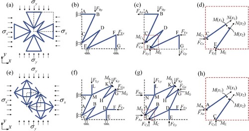
As illustrated in (c), in order to conveniently conduct the force analysis, the symmetric constraints are equivalently replaced by the constraint forces at the points A, C, E and G, as well as the constraint moments at the points C and E. Where FFx and FBy are the equivalent forces of the external loadings and
, and act equivalently at the points F and B:
(2)
(2)
Incorporating the deformation compatibility conditions of the triangle ABC and force equilibrium at points A, B, and C, the longitudinal deformation is calculated as:
(3)
(3) where
,
and
represent the longitudinal deformation, elastic modulus and cross-sectional area of the struts, respectively. Similarly, the transverse deformation of the triangle EFG is calculated as:
(4)
(4) The deformation of the re-entrant construction CDE is obtained by combining the longitudinal deformation at point C and transverse deformation at point E. Referring to the previous work [Citation14], the deformation of the re-entrant construction is analysed based on the Cauchy's theorem. Therefore, firstly, it is necessary to conduct the internal force analysis of the struts CD and DE, as shown in (d). Subsequently, referring to Cauchy's theorem, the strain energy of the re-entrant construction CDE is expressed as:
(5)
(5) where
,
,
and
represent the internal forces, bending moments, distance from cross section to the endpoints and moment of inertia of an area, respectively. Consequently, the deformations at points C and E are calculated as follows:
(6)
(6) As a result, the strains in the longitudinal and transverse direction are calculated as:
(7)
(7)
According to the definition of PR under loading in the longitudinal direction:
(8)
(8)
and to simplify the results, let ,
,
. Besides, calculating the PR under loading in the longitudinal direction, the external load is considered to be
, and considering that the metamaterial AS is of same geometry in orthogonal direction, the PR in both transverse as well as longitudinal directions are expressed as:
(9)
(9)
Indeed, as the theoretical analysis procedure for the metamaterial BS is consistent with that of the metamaterial AS. The PR for metamaterial BS is homoplastically derived as:
(10)
(10)
Based on Equations (9) and (10), plots the programmable PR of the metamaterials, providing a reference for the subsequent additive manufacturing. Apparently, PR of the designed multi-functional metamaterials can be programmed by adjusting the geometrical parameters. In (a,b), the curves with different values of ,
and
almost coincide with each other, indicating that varying
,
and
will not significantly show a influence on PR. Notably, there is a significant positive correlation between PR and
, demonstrating that the PR programmability is primarily achieved by altering the parameter
. Furthermore, considering the additive manufacturability, the in-plane width of the struts
is designed as 0.5 mm [Citation44], and the slenderness ratio
is designed to be lower than 0.1. Therefore, six metamaterials, including ASN, ASZ, ASP, BSN, BSZ and BSP, are designed as illustrated in . Here, the first abbreviation ‘A’ and ‘B’ represent the category A and B metamaterials, respectively. The second abbreviation ‘S’ represents that the metamaterials designed by the fourfold rotation operation of the fundamental unit (TA). The last abbreviation ‘N’, ‘Z’ and ‘P’ represent that the designed metamaterials with the negative, zero and positive PR, respectively. Notably, to effectively avoid the boundary effect, the number of unit cells in each metamaterial is more than 3 × 3 in practical manufacturing. The in-plane width
and out-plane thickness
of the struts are maintained as 0.5 and 2.0 mm, respectively, as well as the specific geometric parameters, relative densities, CTEs and PRs are summarised in . Apparently, the data recorded in indicate that the designed multi-functional metamaterials are expected to integrate the multifunction of low CTE as well as programmable PR, which will be systematically verified in the following experiments.
3. Experiments
3.1. PBF-LB processing
Herein, the designed metamaterials were fabricated by PBF-LB process. Indeed, the bulk Invar 36 alloy was successfully fabricated by PBF-LB in our previous work [Citation36], and the optimal manufacturing quality was achieved at the laser energy density of 99.2 J/mm3. This serves as a crucial foundation for the manufacturing of metamaterials. Furthermore, the published literatures [Citation45–47] demonstrated that, different from bulk materials, the high cooling rates and complex geometries of metamaterials inevitably introduce the manufacturing defects, such as the staircase effects. In addition, an appropriate contour scanning strategy will be beneficial for obtaining the acceptable dimensional accuracy. Accordingly, the contour scanning was introduced based on the meander scanning strategy. Finally, the specific process parameters are as: laser power P = 225 W, scanning speed v = 700 mm/s, layer thickness t = 0.03 mm, hatch spacing h = 0.09 mm, contour distance c = 0.05 mm, contour scanning speed vc = 1400 mm/s. Accordingly, the laser energy density EV is 119.0 J/mm3. Compared with the optimal EV = 99.2 J/mm3 for the bulk Invar 36 alloy, the slightly higher laser energy density here aims at eliminating the poor molten pool fluidity caused by the excessive cooling rate in metamaterials.
Figure 3. Programmable PR with varying parameters λ, γ, θ1 and θ2 for metamaterials (a) AS and (b) BS. The designed certain metamaterials for subsequent additive manufacturing are included.
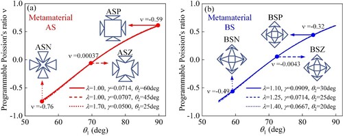
Table 1. The geometrical dimensions of the designed metamaterials for subsequent additive manufacturing with the target relative densities, CTEs and PRs.
The as-fabricated metamaterials along with corresponding unit cells are pictured in . All specimens exhibit a metallic luster without noticeable macroscopic defects. Moreover, records both the theoretical and measured dimensions. Notably, the measured lower heights are caused by wear during the EDM cutting process, whereas the inevitable bonded powder results in marginally thicker struts. In summary, the extremely minimal dimensional deviations in demonstrate the superior dimensional accuracy, thereby ensuring a reliable foundation for subsequent multi-functional integration.
Figure 4. Unit cell and corresponding metamaterials of (a, g) ASN, (b, h) BSN, (c, i) ASZ, (d, j) BSZ, (e, k) ASP and (f, l) BSP. The overall dimensions are marked.
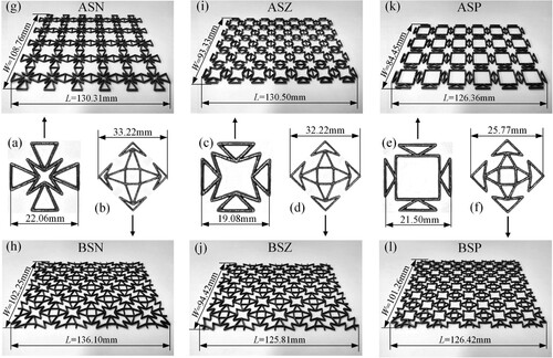
Table 2. Dimensions of the metamaterials (Des. and Exp. represent the design and experimental values, respectively).
3.2. Density and microstructures
In fact, the PBF-LB process inevitably introduces various defects, such as gas pores, keyholes and microcracks, which significantly compromise the macro functions. Therefore, a high densification is crucial for ensuring the exceptional functions of the metamaterials. Consequently, to characterise the densification, based on the Archimedean principle, three repeated densification measurements were conducted on unit cells using the BR-120N electronic densitometer (BEYONGTEST Corporation) with a testing accuracy of 0.0001 g/cm3.
The relative density of the metamaterial can be calculated by the ratio of its density to the density of the bulk Invar 36 alloy (8.105 g/cm3). The density of the metamaterial is determined by the mass-to-characteristic volume ratio, in which the mass measurement was performed using the KFS-F1 electronic balance with a minimum increment of 1 mg, whereas the characteristic volume was determined from the dimensions measured in Section 3.1.
The complex heating process involved in the PBF-LB contributes to a distinctive microstructure, eventually influencing the functions. The metamaterial ASZ was selected as the representative for the microstructure characterisation. In detail, to assess the manufacturing quality at a microscopic scale and explore the defect formation mechanism, the top surface morphology was characterised by using scanning electron microscopy (SEM). Furthermore, optical microscopy (OM) and SEM were employed to characterise the metallography. Prior to the OM examination, the etching was performed for 45 s with a solution comprising 92% alcohol and 8% nitric acid [Citation48].
3.3. Thermal expansion test
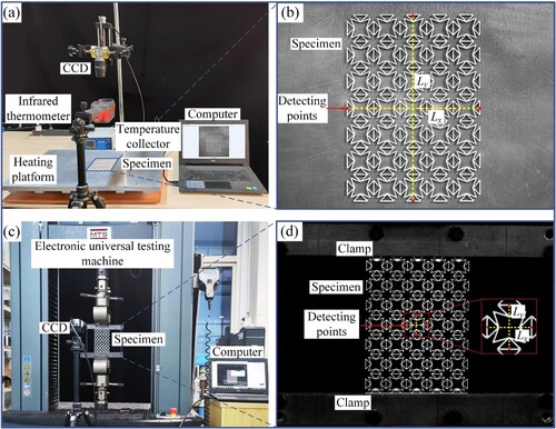
Different from bulk materials, metamaterials can be hardly fulfil the standards for thermal expansion testing by commercial instruments. As a result, a custom-designed CTE testing apparatus, as illustrated in (a), was developed in-house [Citation49]. The main testing principle involves capturing images of the metamaterial at various temperatures and subsequently calculating the thermal deformations based on the relative displacements of the detecting points, as shown in (b). The metamaterials were heated to the target temperature (from room temperature to 200°C) by using a PID (Proportional Integral Derivative)-controlled heating platform (PCE-E600) with a temperature control accuracy of ±1°C. Concurrently, the images during the heating process were captured by using a high-resolution CCD (Charge-Coupled Device) camera (BASLER a2A4504, 4512 × 4512 pixels) with a displacement accuracy of 0.0045 mm. Meanwhile, an infrared thermometer (UNI-T) with a detection accuracy of ±1°C was used to record the temperature. Two repetitive CTE tests were performed in orthogonal direction for each metamaterial. As illustrated in (b), by using ImageJ software, the positional coordinates of each detecting point at different temperatures were collected and subsequently the deformation of the metamaterial was calculated based on the variation of the positional coordinates. Finally, the CTEs in the transverse and longitudinal directions were measured as:
(11)
(11)
Figure 5. Experimental setup and corresponding illustration to calculate the strains in transverse and longitudinal directions in (a, b) CTE and (c, d) PR tests.
where ,
,
,
and
represent the CTEs, initial dimensions, deformed dimensions, room temperature and target temperature, respectively.
3.4. Poisson’s ratio test
As shown in (c), to measure PR, the repetitive quasi-static uniaxial tensile tests were conducted at an ambient temperature, by using an MTS-E45.105-B electronic universal testing machine with a constant strain rate of 1.0 × 10⁻³ s-1. Notably, specialised clamps were designed to fix the metamaterials according our previous work [Citation50]. In addition, a CCD was used to capture the real-time images during the loading process. As illustrated in (d), to avoid the boundary effect, the image processing was conducted on the central unit cells. The calculation of the longitudinal and transverse strains was performed through tracking the positional coordinates of the detecting points using ImageJ software and the PRs were calculated as:
(12)
(12)
3.5. Finite element analysis
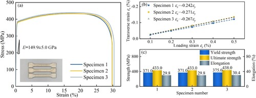
Prior to the finite element analysis (FEA) to further verify the experimental testing, according to standard ASTM E8 [Citation51], the basic properties of PBF-LB Invar 36 alloy were obtained by three repeated uniaxial tensile tests in (a), where the average elastic modulus E = 149.9 GPa was obtained. The PR test results in (b) show good consistency, with an average PR ν = 0.26. Additionally, the average yield strength, ultimate strength and elongation are as 372.3 Mpa, 434.3 Mpa and 0.30, respectively in (c). These obtained experimental data, coupled with our previously measured CTE = 1.95 ppm/°C [Citation32], were subsequently incorporated as material property in the FEA.
Figure 6. (a) Uniaxial tensile stress-strain curves, (b) transverse-loading strain fitting straight line and (c) obtained elongation, strengths of the PBF-LB Invar 36 alloy.
To further verify the experimental tests of the CTE and PR for metamaterials, FEA modelling was conducted. The modelling ensured that the geometry, boundary conditions, loading conditions and results, i.e. CTE and PR measurements remained consistent with those in experiments. The models were meshed by C3D20 hexahedral element, considering the ability to accurately capture the displacement field. Additionally, the mesh sensitivity analysis was performed to ensure a balance between computational accuracy and efficiency. The numerical results will be discussed in Section 4 along with the experimental ones.
4. Results and discussion
4.1. Density and microstructure
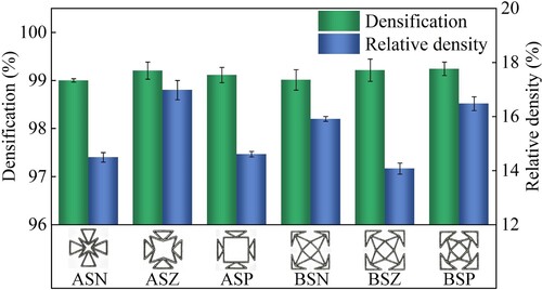
The densification analysis in provides insights into the manufacturing quality. In general, all the metamaterials display a consistently high densification, verified by the lowest recorded densification of 99.0%. This uniformity experimentally verifies that the manufacturing quality herein demonstrate a low geometrical configuration correlation, since the planar metamaterials effectively avoid the overhang and stair step effects usually encountered in the 3D metamaterials. In addition, when comparing the densification of the fabricated metamaterials to that of the bulk Invar 36 alloy [Citation36] that fabricated at the similar process parameters, a slight decrease is observed. This can be explained by the fact that the high specific surface area of the metamaterials, leading to an enhanced powder bonding, and eventually weakening the densification. Besides, the relative density in ranges from 14.2% to 17.6%, confirming the superior lightweight. Notably, despite the fact that the bonded powders marginally increase the mass of the metamaterials, the measured relative density is slightly lower than the theoretical values. This discrepancy is owing to firstly, the inevitable pore defects introduced by PBF-LB process, and secondly, the repeatedly counted mass of the junctions in the theoretical relative density.
Figure 7. Densification and relative density of the metamaterials.
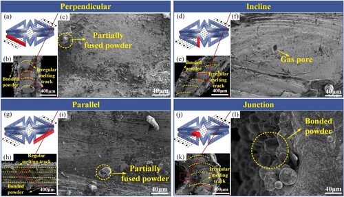
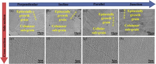
The development of defects in the PBF-LB process is primarily influenced by the flow dynamics of the molten pools [Citation52–54]. Hence, the SEM images in depict the morphology of the top surfaces, which encompass crucial information regarding the flow behaviour of the molten pools. In fact, during the additive manufacturing process, there are variations in the thermal history experienced by different regions of the metamaterial, particularly in the case of the meander scanning strategy. Specifically, the cyclic auxiliary heat process is correlated with the angle between the struts and laser scanning direction. Furthermore, the significant geometric differences between the junctions and struts also lead to the variations in the heat histories. Therefore, as represented by the metamaterial ASZ, its struts are divided into three categories: perpendicular, parallel and inclined struts with respect to the laser scanning direction as illustrated in . In detail, a tight overlapping between the adjacent molten pools in (b, e, h, k) contributes to the superior densification [Citation34]. Specially, compared with other regions, the distinct regular melting tracks are presented in the parallel struts. The large dimensions of the parallel struts in the direction of the scanning vector facilitate the formation of the continuous and regular molten pools, consistent with the findings in ref. [Citation44]. However, Zhang et al. [Citation55] demonstrated that the large dimension in the direction of the scanning vector, such as the parallel struts, contributed to the accumulation of the residual thermal stress, resulting in a warping deformation. Fortunately, this phenomenon is not observed in (h), as the inherent extremely low CTE of Invar 36 alloy effectively suppresses the accumulation of the residual thermal stress. Furthermore, as shown in (e,k), different from other region, the melting tracking at the incline strut and junction is stepwise distributed, as a result of the relation between the strut and laser scanning direction. In fact, this stepwise effect typically weakens the surface quality [Citation45]. However, benefit from the rational contour scanning strategy, no significant surface quality degradation can be observed in (e,k). In addition, as a result of the thermal diffusion of the molten pool into the surrounding loose powder [Citation56,Citation57], a heat-affected zone is formed, and eventually causing the powder around the molten pool to be partially melted and adhered to the surface of the solidified struts, as shown in (b,e,h,k). Moreover, the balling and agglomeration effects of the partially melted powder further promote the powder adhesion [Citation46]. As a result, the bonded powder slightly weakens the dimensional accuracy as given in .
Figure 8. Top surface morphology of (a–c) perpendicular, (d–f) incline and (g–i) parallel struts, as well as (j, k, l) junction of a unit cell of metamaterial ASZ. Relative positions between laser scanning path represented by black dashed arrows and red highlighted characterisation region are marked.
The metallographic images in (b,e,h,k) exhibit numerous large columnar grains epitaxially growth along the <001 > direction, facilitated by remelting between the adjacent molten pools. In addition, a fish-scale molten pool boundary is formed by the Gaussian distribution characteristic of the laser beam, as shown in (b,e,k). Since the excessive heat accumulation at the junctions promote extensive grains growth across the molten pool boundary, an indistinct molten pool boundary was eventually generated in (l) [Citation58]. In addition, (i) shows a uniform microstructure, attributed to the stable melting track facilitating the stable grain growth.
Figure 9. OM micrographs showing the microstructures of (a–c) perpendicular, (d–f) incline and (g–i) parallel struts, as well as (j, k, l) junction of a unit cell of metamaterial ASZ. Relative positions between laser scanning path represented by black dashed arrows and red highlighted characterisation region are marked.
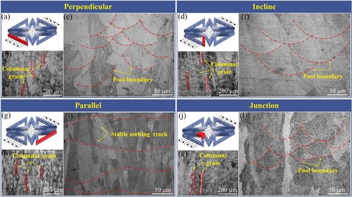
A significant amount of extremely fine sub-grain can be observed in , attributed to the high temperature gradient during the rapid solidification. Additionally, the growth direction of the columnar sub-grain in (a,b,d) is perpendicular to the molten pool boundary, forming the fan-shaped grain clusters, consistent with the reported literature [Citation40]. It is worth noting that caused by the downward-jetting Bénard–Marangoni flows, slightly tortuous and continuously-elongated grains arise at the boundary of the molten pools [Citation58]. The cellular sub-grain structures in (c) are considered as the cross section of the columnar sub-grain structures. Furthermore, resulting from the stable molten pools, a uniformly distributed cellular sub-grain texture is observed in both the junction and different types of struts, as shown in (e–h).
Figure 10. SEM micrographs showing the microstructures of (a, e) perpendicular, (b, f) incline and (c, g) parallel struts, as well as (j, h) junction of a unit cell of metamaterial ASZ with high magnification.
4.2. Low coefficient of thermal expansion
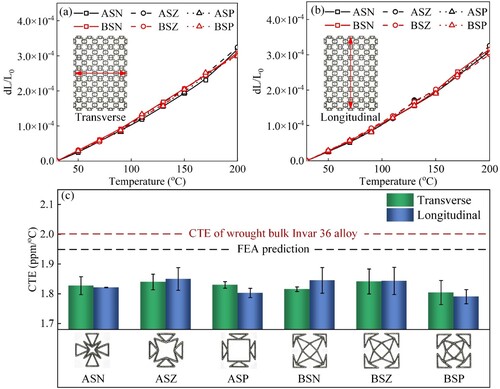
The measured curves in (a,b) present a high consistency for all metamaterials, which demonstrates a similar thermal deformation behaviour. The CTEs derived from the slope of the curves indicate that high temperatures introduce large CTEs in orthogonal direction, consistent with the reported work [Citation36]. This can be attributed to the weakened suppression of atomic vibrations caused by the magnetic-to-volume contraction effect at the high temperature [Citation38]. Furthermore, (c) shows that the CTEs from room temperature up to 200°C obtained both from FEA and experiments are lower than that of wrought bulk Invar 36 alloy (2.0 ppm/°C), validating the low thermal expansion function. In detail, the CTE obtained from FEA remains constant value of 1.95 ppm/°C, as well as the experimental one ranges from 1.79 to 1.85 ppm/°C, suggesting that there are negligible discrepancies in different metamaterials. In fact, the inevitable pores reduce the macroscopic thermal strain by providing the extra space for internal expansion of the microstructure, as a result, causing discrepancies in the CTEs [Citation62]. Benefited from the superior densification as shown in , the effect of the microscopic pores on the CTEs is reasonably neglected. Additionally, it can be observed in (c) that the CTEs in the transverse and longitudinal directions are comparable, resulting from the uniform microstructure as shown in and .
Figure 11. Thermal expansion strain in (a, b) transverse and longitudinal directions versus temperature, as well as the corresponding (c) CTEs from room temperature to 200 °C.
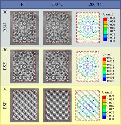
As shown in and , the negligible thermal strain of metamaterials is confirmed by the minimal deviations of the outer contour at room temperature and after being heated up to 200°C. This observation further indicates the low CTEs of these metamaterials. Furthermore, comparing the morphology experimentally obtained at room temperature and 200°C, it is evident that, benefited from the extremely low CTEs, there is no localised non-uniform deformation resulting from the excessive accumulation of thermal stresses. In comparison, the multi-material metamaterials achieve the low CTEs through the accommodation of the thermal deformations of various materials, inevitably leading to localised non-uniform large deformation or even plastic deformation [Citation59]. At 200°C, the morphology obtained through FEA matches well with the experiment. Particularly, the displacement (U) gradually increases in a circular manner from the centre, indicating an isotropic and shape-independent low CTEs. Compared to the existing metamaterials [Citation59] that only achieve low CTEs in the specific directions, the metamaterials designed here with isotropic low CTE clearly demonstrate a broader prospects for engineering applications.
Figure 12. The experimental and numerically calculated thermal deformations for the metamaterials (a) ASN, (b) ASZ and (c) ASP. (Red dashed box represents the original boundary at room temperature.)
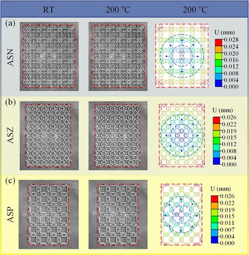
Figure 13. The experimental and numerically calculated thermal deformations for the metamaterials (a) BSN, (b) BSZ and (c) BSP. (Red dashed box represents the original boundary at room temperature.)
4.3. Programmable Poisson’s ratio
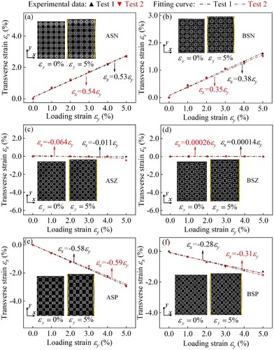
As illustrated in , to eliminate the boundary effect in the experimental results, only the strain data of the central unit cell are extracted here. The PRs are calculated by fitting the slope of the strain curves. Overall, as shown in , an excellent consistency of the data of repeated tests ensures the validity of the experimental results. Notably, the strains in orthogonal direction are linearly correlated, suggesting that the PRs remain approximately constant. In detail, for the metamaterials ASN and BSN in (a, b), the induced transverse strains are in positive values, indicating the transverse extension, effectively validating the negative PR effect. In the case of the metamaterials ASZ and BSZ in (c, d), the transverse strains are maintained closely to zero, confirming the zero PR effect. Additionally, similar to the conventional positive PR materials, the transverse strains of the metamaterials ASP and BSP are in negative values, as shown in (e, f).
Figure 14. Experimental data, fitting curves and digital images of the deformation process of metamaterials (a) ASN, (b) BSN, (c) ASZ, (d) BSZ, (e) ASP and (f) BSP under Poisson’s ratio tests.
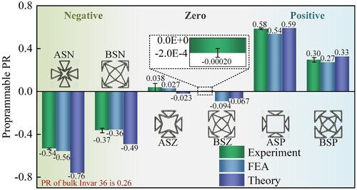
As plotted in , the minor discrepancies between the experimental, FEA, and theoretical predictions validate the theoretical design. Furthermore, the programmable PR of these metamaterials is fully confirmed by the programmability of the negative, zero as well as positive PRs on the basis of a constant PR of 0.26 of the constituent material. However, during the loading process, the deformation behaviour is affected by the coupling of various factors, such as geometric configurations, microstructure, and manufacturing quality. Consequently, there are inevitable deviations between the experimental results and theoretical predictions. The underlying mechanisms responsible for these discrepancies will be discussed in following section.
Figure 15. Programmable Poisson’s ratio obtained by experiment, FEA and theoretical prediction.
4.4. Deformation mechanisms
illustrates the deformation behaviour of the metamaterials under the tensile loading. Specially, according to the symmetry, it is equivalent to analyse the deformation behaviour of a quarter unit cell, as depicted in (a,d,g). Indeed, considering a negligible deformation of the triangle ABC results from its high stiffness [Citation60], the analysis of the deformation behaviour is simplified as shown in (c, f, i). Firstly, for the metamaterials with negative PR, as illustrated in (c), when subjected to a longitudinal loading, the movement of the point C along the loading direction causes an increase in the angle θ1. Then, the strut DE undergoes both translational and rotational motion under the driving force from the strut CD. It is noteworthy that a competing effect on the transverse strain is exerted by the translational and rotational motion of the strut DE. Specifically, the translational motion induces the extension of the re-entrant structure, while in contrast, the rotational motion causes the contraction. Clearly, with a small θ1, the transverse deformation behaviour is dominated by the translational motion, resulting in a negative PR. This can be validated by the curves in , where a small θ1 corresponds to a negative PR.
Figure 16. Schematic deformation of metamaterials with (a–c) negative, (d–f) zero and (g–i) positive PR under tensile loading.
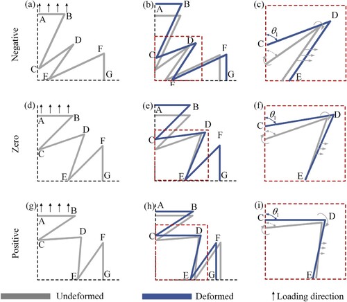
Instead, the large θ1 hinders the translational motion of the strut DE, and thus suppressing the transverse expansion behaviour. Accordingly, for the metamaterials with zero PR, the effects from translational and rotational motions of the strut DE offset each other, resulting in a negligible transverse strain, as shown in (f). Furthermore, as shown in (i), the excessively large θ1 results in the rotational motion dominating the transverse deformation, causing the transverse contraction, and eventually achieving the positive PR. In fact, as the longitudinal loading continues, the angle θ1 gradually increases, causing metamaterials to tend towards a positive PR. However, this tendency is not observed in , attributing to the limited loading range (strain less than 5%).
The experimental and FEA images in and reveal that the triangular structure within the metamaterial undergoes negligible deformation, and the angle θ1 of the re-entrant structure gradually increases, fully confirming the above deformation mechanism. Furthermore, upon comparing the outer contours of the metamaterials, the evident transverse expansion is observed in (a) and (a), serving as a compelling evidence to affirm the negative PR effect. Simultaneously, the alignment of the outer contour in the transverse direction in (b) and (b), as well as the transverse contraction phenomenon in (c) and (c), respectively, provide experimental evidence for the zero and positive PRs.
Figure 17. The experimental deformation and numerically calculated equivalent plastic strain (PEEQ) for the metamaterials (a) ASN, (b) ASZ and (c) ASP. (Red dashed box marks the boundary of the metamaterial before loading).
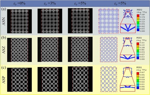
Figure 18. The experimental deformation and numerically calculated equivalent plastic strain (PEEQ) for the metamaterials (a) BSN, (b) BSZ and (c) BSP. (Red dashed box marks the boundary of the metamaterial before loading).
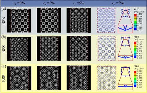
It should be noted that the deformation behaviour is influenced by various factors, resulting in deviations between the experimental results and theoretical predictions in . The contour plots of the numerically calculated equivalent plastic strain (PEEQ) distribution in and 18 illustrate that the inevitable introduction of plastic deformation at the junctions, consequently impacting the enlargement of the angle θ1 and ultimately resulting in deviations from the expected outcome [Citation50]. In addition, the stiffness of the junction is neglected in the theoretical analysis. However, in the case of the metamaterials fabricated by PBF-LB, the junctions are solid parts with a specific depth and width, creating certain rotational resistance to the struts, thus limiting the transverse deformation behaviour of the metamaterials, and thus ultimately leads to the value of PR approaching zero [Citation35]. Besides, the rough surface caused by the bonded powder induces stress concentration, leading to local premature yielding and ultimately affecting the deformation behaviour [Citation61]. On the other hand, the bonded powder leads to a large volume of the junction, reducing the actual length of the struts, and therefore diminishes the transverse deformation, ultimately resulting in a smaller magnitude of PR.
4.5. Coupling performance
The radar chart in systematically displays the comprehensive performance of the designed multi-functional metamaterials. The coordinate axes composed of four arrows represent four performances or functions: programmable PR, low CTE, densification and relative density. In detail, the designed metamaterials achieving PR tuning in the range of −0.54∼+0.58, confirming an expected PR programmability. The low CTEs, high densification represent superior performances in terms of low thermal expansion and manufacturability [Citation36], respectively. In addition, despite the unavoidable variations in relative density results from the geometric parameters, the designed metamaterials still demonstrate exceptional lightweight performance, as the highest relative density remains below 0.2. Apparently, the designed metamaterials achieve the integration of the low CTE and programmable PR functions while ensuring the lightweight and manufacturability. Indeed, limited by the manufacturing process, reported works [Citation14–28] integrate the above functions by means of multiple polymer-based metamaterials, which inevitably introduce a limited operating temperature range as well as weak mechanical performances. This severely limits their widespread utilisation in the engineering. Notably, herein, the designed metamaterials utilise Invar 36 alloy as the constituent material, breaking the manufacturing process limitations while providing superior mechanical performances and a wider operating temperature range, demonstrating a broader application prospect.
Figure 19. Comprehensive capacity, incorporating the programmable Poisson’s ratio, low thermal expansion, lightweight and manufacturability of multi-functional metamaterials.
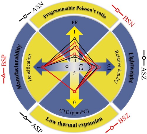
In , the quadrilateral formed by the points on the four coordinate axes represents the comprehensive capacity of each metamaterial. In general, a larger quadrilateral represents a more comprehensive performance. However, herein, the value of PR, as a characteristic, represents the function variation of the metamaterial rather than the performance superiority or inferiority. Each metamaterial provides the unique benefits for fulfilling the multiple customised requirements in engineering applications. For instance, the metamaterials ASN and BSN simultaneously couple the low CTE as well as negative PR, meeting with the requirements for the energy absorption characteristics in temperature-varying environments. If the geometric stability under simultaneous temperature and mechanical loads is required, the metamaterials ASZ and BSZ are the suitable candidates, benefiting from the integration of low CTE and near-zero PR functions. And for the metamaterials ASP and BSP, which simultaneously achieve low CTE as well as positive PR, are considered to be widely applied to the load-bearing components in temperature-varying environments. In addition, in order to overcome the limitations imposed by the inherent anisotropy of planar metamaterials and to further broaden the application prospects of the designed multi-functional metamaterials, the 3D multifunctional metamaterials, which can realise the isotropy and multi-functional integration [Citation63], are the next objectives of our research.
5. Conclusions
Herein, by using Invar 36 alloy as the constituent material, a series of multi-functional metamaterials integrated low CTE and programmable PR were developed, and additively manufactured by PBF-LB. The manufacturability, lightweight, low CTE and programmable PR functions were systematically characterised and verified. Furthermore, the underlying mechanisms of the process-microstructure-functions were originally revealed. The main conclusions are as follow:
Superior manufacturing quality and uniform microstructure are achieved by the correct design of process parameters and scanning strategy. The bonded powder particles caused by the thermal diffusion of the molten pool slightly weaken the densification and dimensional accuracy of the metamaterials.
Benefited from the uniform microstructure and superior manufacturing quality, the isotropic low thermal expansion functions (CTE < 2.0 ppm/°C) are obtained in the devised metamaterials. In particularly, attributed to the weakened suppression of atomic vibrations by the magnetic-to-volume contraction effect, the high loading temperatures introduce the relatively large CTE.
High dimensional accuracy ensures the programmable PR function of the manufactured metamaterials. The PR is realised to be programmable in the range of −0.54∼+0.58, fully confirming the PR programmability of the metamaterials and the effectiveness of the theoretical designs.
The underlying mechanism of the programmable PR is disclosed. The transverse strain of the metamaterial is dominated by the re-entrant construction. A small angle θ1 facilitates transverse extension of the re-entrant construction, achieving a negative PR. In contrast, a large angle θ1 promotes the PR towards positive values.
Disclosure statement
No potential conflict of interest was reported by the author(s).
Data availability statement
All data obtained or analysed in this work are included in this manuscript.
Additional information
Funding
References
- Veselago VG. Electrodynamics of substances with simultaneously negative and magnetic permeabilities. Soviet Physics Uspekhi. 1967;92(7):517.
- Chen T, Pauly M, Reis PM. A reprogrammable mechanical metamaterial with stable memory. Nature. 2021;589(7842):386–390. doi:10.1038/s41586-020-03123-5
- Shelby RA, Smith DR, Schultz S. Experimental verification of a negative index of refraction. Science. 2001;292(5514):77–79. doi:10.1126/science.1058847
- Li J, Chan CT. Double-negative acoustic metamaterial. Physical Review E. 2004;70(5):055602. doi:10.1103/PhysRevE.70.055602
- Bossart A, Dykstra DMJ, van der Laan J, et al. Oligomodal metamaterials with multifunctional mechanics. Proc Natl Acad Sci USA. 2021;118(21):e2018610118. doi:10.1073/pnas.2018610118
- Huang C, Chen L. Negative Poisson's ratio in modern functional materials. Adv Mater. 2016;28(37):8079–8096. doi:10.1002/adma.201601363
- Wei K, Chen H, Pei Y, et al. Planar lattices with tailorable coefficient of thermal expansion and high stiffness based on dual-material triangle unit. J Mech Phys Solids. 2016;86:173–191. doi:10.1016/j.jmps.2015.10.004
- Al-Ketan O, Abu Al-Rub RK. Multifunctional mechanical metamaterials based on triply periodic minimal surface lattices. Adv Eng Mater. 2019;21(10):201900524. doi:10.1002/adem.201900524
- Xu X, Wu Q, Pang Y, et al. Multifunctional metamaterials for energy harvesting and vibration control. Adv Funct Mater. 2021;32(7):202107896. doi:10.1002/adfm.202107896
- Fan J, Song B, Zhang L, et al. Structural design and additive manufacturing of multifunctional metamaterials with low-frequency sound absorption and load-bearing performances. Int J Mech Sci. 2022;238:107848. doi:10.1016/j.ijmecsci.2022.107848
- Kumar R, Kumar M, Chohan JS, et al. Overview on metamaterial: History, types and applications. Mater Today Proc. 2022;56:3016–3024. doi:10.1016/j.matpr.2021.11.423
- Bisoffi M, Hjelle B, Brown DC, et al. Detection of viral bioagents using a shear horizontal surface acoustic wave biosensor. Biosens Bioelectron. 2008;23(9):1397–1403. doi:10.1016/j.bios.2007.12.016
- Shen SH, Fang W, Young ST. Design considerations for an acoustic MEMS filter. Microsyst Technol. 2004;10(8-9):585–591. doi:10.1007/s00542-003-0335-6
- Wei K, Peng Y, Qu Z, et al. A cellular metastructure incorporating coupled negative thermal expansion and negative Poisson's ratio. Int J Solids Struct. 2018;150:255–267. doi:10.1016/j.ijsolstr.2018.06.018
- Li X, Gao L, Zhou W, et al. Novel 2D metamaterials with negative Poisson’s ratio and negative thermal expansion. Extreme Mech Lett. 2019;30:100498. doi:10.1016/j.eml.2019.100498
- Ai L, Gao XL. Three-dimensional metamaterials with a negative Poisson's ratio and a non-positive coefficient of thermal expansion. Int J Mech Sci. 2018;135:101–113. doi:10.1016/j.ijmecsci.2017.10.042
- Ai L, Gao XL. Metamaterials with negative Poisson’s ratio and non-positive thermal expansion. Compos Struct. 2017;162:70–84. doi:10.1016/j.compstruct.2016.11.056
- Ng CK, Saxena KK, Das R, et al. On the anisotropic and negative thermal expansion from dual-material re-entrant-type cellular metamaterials. J Mater Sci. 2016;52(2):899–912. doi:10.1007/s10853-016-0385-7
- Wang Q, Jackson JA, Ge Q, et al. Lightweight mechanical metamaterials with tunable negative thermal expansion. Phys Rev Lett 2016;117(17):175901. doi:10.1103/PhysRevLett.117.175901
- Peng X-L, Bargmann S. A novel hybrid-honeycomb structure: Enhanced stiffness, tunable auxeticity and negative thermal expansion. Int J Mech Sci. 2021;190:106021. doi:10.1016/j.ijmecsci.2020.106021
- Zheng B-B, Fu M-H, Li W-H, et al. A novel re-entrant honeycomb of negative thermal expansion. Smart Mater Struct. 2018;27(8):085005. doi:10.1088/1361-665X/aacf73
- Wang Y, Gao J, Luo Z, et al. Level-set topology optimization for multimaterial and multifunctional mechanical metamaterials. Eng Optim. 2016;49(1):22–42. doi:10.1080/0305215X.2016.1164853
- Ha CS, Hestekin E, Li J, et al. Controllable thermal expansion of large magnitude in chiral negative Poisson's ratio lattices. Phys Status Solidi B. 2015;252(7):1431–1434. doi:10.1002/pssb.201552158
- Wu L, Li B, Zhou J. Isotropic negative thermal expansion metamaterials. ACS Appl Mater Interfaces. 2016;8(27):17721–17727. doi:10.1021/acsami.6b05717
- Yu H, Wu W, Zhang J, et al. Drastic tailorable thermal expansion chiral planar and cylindrical shell structures explored with finite element simulation. Compos Struct. 2019;210:327–338. doi:10.1016/j.compstruct.2018.11.043
- Han Z, Wei K. Multi-material topology optimization and additive manufacturing for metamaterials incorporating double negative indexes of Poisson’s ratio and thermal expansion. Addit Manuf. 2022;54:102742. doi:10.1016/j.addma.2022.102742
- Chen M-M, Fu M-H, Lan L-H, et al. A novel 3D structure with tunable Poisson’s ratio and tailorable coefficient of thermal expansion based on a tri-material triangle unit. Compos Struct. 2020;253:112803. doi:10.1016/j.compstruct.2020.112803
- Fu M, Huang J, Zheng B, et al. Three-dimensional auxetic materials with controllable thermal expansion. Smart Mater Struct. 2020;29(8):085034. doi:10.1088/1361-665X/ab9dda
- Ahadi A, Matsushita Y, Sawaguchi T, et al. Origin of zero and negative thermal expansion in severely-deformed superelastic NiTi alloy. Acta Mater. 2017;124:79–92. doi:10.1016/j.actamat.2016.10.054
- Qiu C, Adkins NJE, Attallah MM. Selective laser melting of Invar 36: Microstructure and properties. Acta Mater. 2016;103:382–395. doi:10.1016/j.actamat.2015.10.020
- Zheng J-J, Li C-S, He S, et al. Microstructural and tensile behavior of Fe-36%Ni alloy after cryorolling and subsequent annealing. Mater Sci Eng A. 2016;670:275–279. doi:10.1016/j.msea.2016.06.004
- Wei K, Yang Q, Ling B, et al. Mechanical properties of Invar 36 alloy additively manufactured by selective laser melting. Mater Sci Eng A. 2020;772:138799. doi:10.1016/j.msea.2019.138799
- Qiu C, Liu Y, Liu H. Influence of addition of TiAl particles on microstructural and mechanical property development in Invar 36 processed by laser powder bed fusion. Addit Manuf. 2021;48:102457. doi:10.1016/j.addma.2021.102457
- Zhang C, Zhou Y, Wei K, et al. High cycle fatigue behaviour of Invar 36 alloy fabricated by laser powder bed fusion. Virtual Phys Prototyp. 2023;18(1):2190901. doi:10.1080/17452759.2023.2190901
- Wei C, Gu H, Li Q, et al. Understanding of process and material behaviours in additive manufacturing of Invar36/Cu10Sn multiple material components via laser-based powder bed fusion. Addit Manuf. 2021;37:101683. doi:10.1016/j.addma.2020.101683
- Yang Q, Wei K, Yang X, et al. Microstructures and unique low thermal expansion of Invar 36 alloy fabricated by selective laser melting. Mater Charact. 2020;166:110409. doi:10.1016/j.matchar.2020.110409
- Yakout M, Elbestawi MA, Veldhuis SC. A study of thermal expansion coefficients and microstructure during selective laser melting of Invar 36 and stainless steel 316L. Addit Manuf. 2018;24:405–418. doi:10.1016/j.addma.2018.09.035
- Harrison NJ, Todd I, Mumtaz K. Thermal expansion coefficients in Invar processed by selective laser melting. J Mater Sci. 2017;52(17):10517–10525. doi:10.1007/s10853-017-1169-4
- Asgari H, Salarian M, Ma H, et al. On thermal expansion behavior of invar alloy fabricated by modulated laser powder bed fusion. Mater Des. 2018;160:895–905. doi:10.1016/j.matdes.2018.10.025
- Wegener T, Brenne F, Fischer A, et al. On the structural integrity of Fe-36Ni Invar alloy processed by selective laser melting. Addit Manuf. 2021;37:101603. doi:10.1016/j.addma.2020.101603
- Yakout M, Cadamuro A, Elbestawi MA, et al. The selection of process parameters in additive manufacturing for aerospace alloys. Int J Adv Manuf Technol. 2017;92(5-8):2081–2098. doi:10.1007/s00170-017-0280-7
- Yakout M, Elbestawi MA, Veldhuis SC. Density and mechanical properties in selective laser melting of Invar 36 and stainless steel 316L. J Mater Process Technol. 2018;266:397–420. doi:10.1016/j.jmatprotec.2018.11.006
- He GX, Peng H, Zhou G, et al. Superior mechanical properties of Invar36 alloy lattices structures manufactured by laser powder bed fusion. Materials (Basel). 2023;16(12):4433. doi:10.3390/ma16124433
- Mahmoud D, Al-Rubaie KS, Elbestawi MA. The influence of selective laser melting defects on the fatigue properties of Ti6Al4V porosity graded gyroids for bone implants. Int J Mech Sci. 2021;193:106180. doi:10.1016/j.ijmecsci.2020.106180
- Yang L, Yan C, Cao W, et al. Compression–compression fatigue behaviour of gyroid-type triply periodic minimal surface porous structures fabricated by selective laser melting. Acta Mater. 2019;181:49–66. doi:10.1016/j.actamat.2019.09.042
- Yang X, Yang Q, Shi Y, et al. Effect of volume fraction and unit cell size on manufacturability and compressive behaviors of Ni-Ti triply periodic minimal surface lattices. Addit Manuf. 2022;54:102737. doi:10.1016/j.addma.2022.102737
- Milleret A, Laitinen V, Ullakko K, et al. Laser powder bed fusion of (14 M) Ni-Mn-Ga magnetic shape memory alloy lattices. Addit Manuf. 2022;60:103231. doi:10.1016/j.addma.2022.103231
- Yang Q, Yang S, Ma S, et al. In-situ X-ray computed tomography tensile tests and analysis of damage mechanism and mechanical properties in laser powder bed fused Invar 36 alloy. J Mater Sci Technol. 2024;175:29–46. doi:10.1016/j.jmst.2023.08.014
- Wei K, Xiao X, Xu W, et al. Large programmable coefficient of thermal expansion in additively manufactured bi-material mechanical metamaterial. Virtual Phys Prototyp. 2021;16(sup1):S53–S65. doi:10.1080/17452759.2021.1917295
- Ling B, Wei K, Wang Z, et al. Experimentally program large magnitude of Poisson's ratio in additively manufactured mechanical metamaterials. Int J Mech Sci. 2020;173:105466. doi:10.1016/j.ijmecsci.2020.105466
- ASTM International. Standard test methods for tension testing of metallic materials. ASTM Standardization News. 2016.
- Leung CLA, Marussi S, Towrie M, et al. The effect of powder oxidation on defect formation in laser additive manufacturing. Acta Mater. 2019;166:294–305. doi:10.1016/j.actamat.2018.12.027
- Guo Q, Qu M, Escano LI, et al. Revealing melt flow instabilities in laser powder bed fusion additive manufacturing of aluminum alloy via in-situ high-speed X-ray imaging. Int J Mach Tools Manuf. 2022;175:103861. doi:10.1016/j.ijmachtools.2022.103861
- Khairallah SA, Anderson AT, Rubenchik A, et al. Laser powder-bed fusion additive manufacturing: Physics of complex melt flow and formation mechanisms of pores, spatter, and denudation zones. Acta Mater. 2016;108:36–45. doi:10.1016/j.actamat.2016.02.014
- Zhang W, Shi Y, Liu B, et al. Consecutive sub-sector scan mode with adjustable scan lengths for selective laser melting technology. Int J Adv Manuf Technol. 2008;41(7-8):706–713. doi:10.1007/s00170-008-1527-0
- Al-Saedi DSJ, Masood SH, Faizan-Ur-Rab M, et al. Mechanical properties and energy absorption capability of functionally graded F2BCC lattice fabricated by SLM. Mater Des. 2018;144:32–44. doi:10.1016/j.matdes.2018.01.059
- Yan C, Hao L, Hussein A, et al. Advanced lightweight 316L stainless steel cellular lattice structures fabricated via selective laser melting. Mater Des. 2014;55:533–541. doi:10.1016/j.matdes.2013.10.027
- Yadollahi A, Shamsaei N, Thompson SM, et al. Effects of process time interval and heat treatment on the mechanical and microstructural properties of direct laser deposited 316L stainless steel. Mater Sci Eng A. 2015;644:171–183. doi:10.1016/j.msea.2015.07.056
- Yu H, Wang H, Guo X, et al. Building block design for composite metamaterial with an ultra-low thermal expansion and high-level specific modulus. Compos Struct. 2022;300:116131. doi:10.1016/j.compstruct.2022.116131
- Logakannan KP, Ramachandran V, Rengaswamy J, et al. Stiffened star-shaped auxetic structure with tri-directional symmetry. Compos Struct. 2022;279:114773. doi:10.1016/j.compstruct.2021.114773
- Gao J, Gu D, Ma C, et al. Formation process and mechanical deformation behavior of a novel laser-printed compression-induced twisting-compliant mechanism. Engineering-PRC. 2022;15:133–142. doi:10.1016/j.eng.2021.03.032
- Yang LM, Ferrucci R, Mertens W, et al. An investigation into the effect of gradients on the manufacturing fidelity of triply periodic minimal surface structures with graded density fabricated by selective laser melting. J Mater Process Technol. 2020;275:116367. doi:10.1016/j.jmatprotec.2019.116367
- Li Z, Li X, Wang Z, et al. Multifunctional sound-absorbing and mechanical metamaterials via a decoupled mechanism design approach. Mater Horiz. 2023;10:75–87. doi:10.1039/D2MH00977C