
 ?Mathematical formulae have been encoded as MathML and are displayed in this HTML version using MathJax in order to improve their display. Uncheck the box to turn MathJax off. This feature requires Javascript. Click on a formula to zoom.
ABSTRACT
For vat photopolymerization 3D printing technology with high-viscosity ceramic slurry, the cleaning of residual uncured slurry presents a challenging task for lattice-based porous structures. Hence, this study contributes a multi-scale topology optimisation method for lattice-solid hybrid structures dedicated to ceramic vat photopolymerization 3D printing. A novel flushing jet accessibility constraint is proposed, aiming to effectively remove the residual uncured slurry after finishing the vat photopolymerization. Specifically, a multi-material interpolation for graded lattices and solid materials is introduced to form the fundamental of topology optimisation. Then, a series of filtering and projection operations are developed to ensure the accessibility of flushing waters to every location that may have residual ceramic slurry. Accordingly, a multi-scale topology optimisation mathematical model is established and solved with the adjoint sensitivities. 2D and 3D numerical examples are conducted to evaluate the effectiveness of the proposed method. Furthermore, a 3D printing experiment is performed to validate the full water jet accessibility of the optimised structural solution and one pillow bracket part is carried out as a practical application demonstration.
1. Introduction
Topology optimisation has emerged as a vital tool for innovative structural design by mathematically optimising the material distribution to achieve optimal target performance [Citation1–3]. In recent years, the rapid advancement of additive manufacturing technology has brought the topology optimisation method into the spotlight for high-performance lightweight structure design, particularly the multi-scale structures with porous microstructure infill [Citation4–8]. A series of porous structure patterns that are traditionally unmanufacturable have been successfully processed with additive manufacturing. Compared to traditional macro-scale only solid structures, the novel multi-scale designs achieve several remarkable mechanical properties, including high porosity, energy absorption, robustness, negative Poisson's ratio, and ultimate anisotropy [Citation9,Citation10]. However, even with the great manufacturing flexibility of additive technology, the multi-scale designs still face a number of critical manufacturability issues that should be carefully addressed during design algorithm development [Citation11–13].
The first consideration is the printability of multi-scale structures through additive manufacturing. The minimum length scale is a significant characteristic for evaluating printability [Citation14,Citation15] given the limited machine resolutions. Due to scale separation, multi-scale topology optimisation can be performed without knowing the actual unit cell size. However, to apply the minimum length scale control, both the pixel resolution within the microstructure and the unit cell size for CAD model generation [Citation16] should be known as the premise. In case of infilling with geometrically simple microstructures (known as lattices), the minimum structural size can be defined by simultaneously constraining the relative density lower bound of the lattices and pre-defining the unit cell size for model generation [Citation17–19]. For multi-scale components with free-form topological microstructures, the minimum length scale control can be realised by processing the micro-scale topological variables [Citation20,Citation21] through filtering and projection formulations [Citation22,Citation23], structural skeleton-assisted formulation [Citation24], the MMC (moving morphable components) configuration [Citation25], etc. Note that the unit cell size is closely linked to the microstructure periodicity for which a large number of repeating microstructures are required to ensure the accuracy of the homogenisation-based computation. However, subject to the fixed minimum length scale requirement, the smaller unit cell size for ensuring periodicity indicates a larger length scale lower limit for the dimensionless microstructure optimisation, leading to less structure variation and therefore the performance degradation. Hence, the unit cell size should be carefully determined and an intermediate size is generally preferred. Full-scale re-analysis and experimental tests can be effective means to verify the appropriateness of the unit cell size determination [Citation26–29].
In addition to the minimum size control, two other challenges are also involved given the additive manufacturing characteristics that deserve special attention: support structure issue and residual uncured material cleaning.
In many additive manufacturing processes, support structures are required to ensure the construction of large overhang areas, which significantly increase the manufacturing time and entail additional post-processing steps for their removal [Citation30,Citation31]. For many multi-scale designs, the mutual connection between periodic microstructures ensures the structure self-supporting, especially for the cases with simple macro topology [Citation17–19]. When conducting freeform topology optimisation at both macro- and micro-scales, the application of self-supporting constraints in both scales proves to be necessary to address the support structure issue [Citation32,Citation33]. Additionally, a compromise approach is to ensure the removability of the support structure. For instance, the support structure is exclusively adopted at the open boundaries of the structure, while the enclosed voids are filled with self-supporting microstructures [Citation34]. The utilisation of graded lattice infill is also beneficial to achieve better structural buckling strength [Citation35,Citation36]. Utilising teethed connections at the part-support interface is also an approach to facilitating easy support removal.
The fabrication of multi-scale structures is generally performed with high-precision laser-based additive manufacturing processes [Citation37,Citation38], such as powder bed fusion, binder jetting, vat photopolymerization, etc. For these techniques, the removal of base materials that adhered to the sintered/cured part is a necessary post-processing step, thereby introducing new considerations to structural design.
The most fundamental requirement is to avoid self-enclosed voids so that the residual base materials have the channel to remove. In traditional single-scale structure design, the constraint on eliminating self-enclosed voids can be implied by the Virtual Temperature Method [Citation39]. With this approach, all enclosed voids are regarded as heat sources and the solids around the cavities are regarded as insulators. Zhou et al. [Citation40] introduced a feature-based method to guarantee void connectivity, wherein the void feature is used as the basic design primitive, and the void centers are constrained to fall outside the design domain through the so-called side constraints. For multi-scale structures, the avoidance of self-enclosed voids must be addressed at both the macro- and micro-scales but research efforts on eliminating microstructure enclosed voids seem less focused.
For ceramic vat photopolymerization 3D printing, the studied additive manufacturing process in this research, high-viscosity ceramic slurry is cured with UV-lights in the layer-by-layer approach, tremendous residual base materials are attached to the cured part and the residual slurry cleaning is very troublesome [Citation41–44]. Some process modifications have been proposed to achieve excellent cleaning results for non-complex geometries [Citation41,Citation44]. As for topology optimisation, the related structural designs are complex with two-scale structural details and even if enclosed voids can be avoided, undercut features still exist inside the structure that the water jets for cleaning have dead zones that cannot approach. Hence, topology optimisation with flushing jet accessibility considerations should be formulated at the design stage to guarantee the removability of the residual ceramic slurry. The flushing jet accessibility indicates that the high-viscosity residual base materials attached to the cured ceramic body can be directly accessed by the straight-line water jets. In the reported manufacturing results, the multi-scale structures for ceramic 3D printing are designed to be fully porous lattice structures to avoid any non-permeable solids, and thereby, the water jets can pass through the intra-lattice voids for cleaning [Citation43,Citation45]. However, as proved in literature [Citation46,Citation47], the incorporation of a solid phase in lattice infilled multi-scale components, realising the lattice-solid hybrid structure (LSHS), reinforces the mechanical performance of the macro-structure. However, introducing solids brings in the extra challenge of addressing the flushing accessibility issue, and this challenge has yet been targeted.
Exploring the concurrent optimisation of LSHSs while imposing manufacturability constraints holds great significance. Hence, in this study, we focus on addressing the issue of residual base material cleaning for 3D printed ceramic LSHSs. Specifically, we propose a multi-material interpolation for graded lattices and solids. The macro elements falling in the lattice range would be treated as water passages, while only the macro elements with high densities indicating solids will be processed for flushing jet accessibility. A series of novel filtering and projection methods are developed to achieve the structural flushing jet accessibility, i.e. ensuring every surface area of the solid phase can be accessed by the water jets. Subsequently, the multiscale topology optimisation mathematic model for LSHSs is formulated and the sensitive analysis is performed to obtain the gradient information for design update. Numerical examples are comparatively studied based on the proposed method with varying constraint conditions and the obtained numerical results will be discussed in details to disclose the effectiveness. Finally, additive manufacturing experiments are conducted that proves the effectiveness of the proposed method.
The remainder of this paper is structured as follows. Section 2 illustrates the problem formulation of the proposed multi-scale topology optimisation. In Section 3, 2D and 3D numerical examples are studied to demonstrate the effectiveness of the proposed method. Section 4 presents additive manufacturing experiment details to validate the optimisation effects. Section 5 studies a practical engineering case by using the proposed method. Finally, Section 6 summarises the current work.
2. Problem formulation
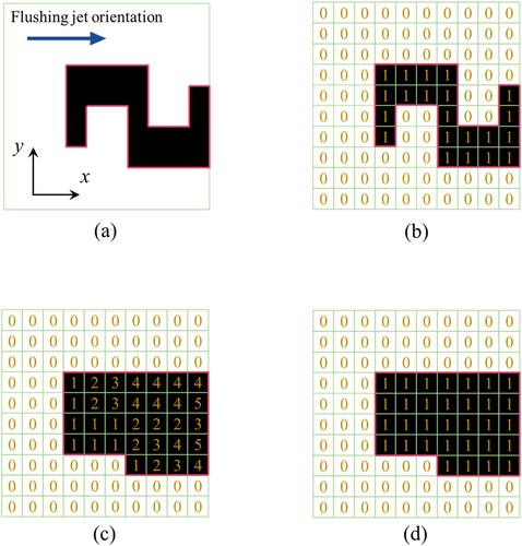
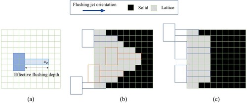
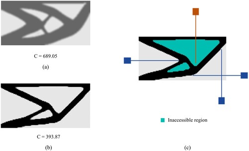
Vat photopolymerization 3D printing exhibits remarkable application prospects owing to its economic benefits, shape building flexibility, and the biocompatibility, among others [Citation48,Citation49]. The vat photopolymerization 3D printing process for ceramics is schematically demonstrated in with generally three process steps. In the first step, the software slices the to-build CAD model into layers and generates the laser scanning path code for input to the 3D printer. Then, the ceramic slurry from the material feeder is coated onto the build platform by the scraper and selectively cured under UV light irradiation following the path code. Afterwards, the build platform is lowered to a distance (equals the layer thickness) and slurry is recoated on top of the current layer by the scraper and repeated with selective curing till finishing the part. Therefore, it is common that a large amount of uncured slurry attaches to the part body after the curing step. Subsequently, the next and critical step is to remove the residual ceramic slurry from the part body, usually with a water or air jet (even combined with ultrasonic cleaning). In the final step, the part is put into a high-temperature and high-pressure furnace for degreasing and sintering treatment to densify the solids for further mechanical property enhancement. Amongst the above vat photopolymerization procedures, the cleaning step is critical since the incomplete removal of residual ceramic slurry would add additional weight to the part and degrade the shape accuracy and surface quality of the sintered part. However, for holes, channels and other intricate geometries that cannot be accessed by the water jet, removing the residual slurry becomes a sophisticated or even unfeasible mission. As illustrated in , assuming only a unidirectional flushing jet is involved, the shaded areas represent the inaccessible regions since the flushing jet can only penetrate the lattices (marked in grey) but not the solids (marked in black). Therefore, accessibility of the flushing water jets to all cleaning-needed regions should be carefully addressed when optimising the structure. Note that, vacuum cleaning is performed in [Citation50,Citation51] for removing the residual liquid resin in a layer-based manner. However, this type of in-situ processing is not suitable for our vat photopolymerization 3D printing, since the residual ceramic slurry plays as the foundation of scraping and depositing a new layer of raw materials. It is also infeasible to remove the residual slurry after part curing since the slurry is stickier than liquid resin and vacuuming the porous part would be demanding on the vacuum force that very likely breaks the thin struts.
Figure 1. The vat photopolymerization 3D printing process for ceramics.
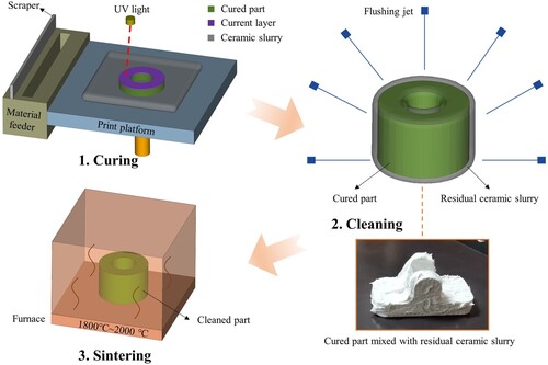
Figure 2. Illustration of the flushing jet accessibility for lattice-solid hybrid structures.
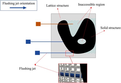
Due to the permeability of the lattices, the lattice-filled multi-scale structures are considered to be manufacturing-friendly designs for ceramic vat photopolymerization 3D printing. Hence, in case of involving the solid reinforcement phase, we consider the lattice phase as effective water jet passages that the flushing water can pass through it to clean the boundary region of the solid phase following the predefined jet flow direction, as illustrated in . Inspired by the surface accessibility constraints [Citation52–54] within the framework of density-based structural optimisation, the numerical method for ensuring the flushing jet accessibility for lattice-solid hybrid structures have been developed in this research and explicitly illustrated in the following subsections. To the best of our knowledge, this is the first proposed method to resolve the residual base material removal issue amongst the many topology optimisation works for additive manufacturing.
2.1 Material model
2.1.1 Filters
In this subsection, three types of filters are introduced to avoid mesh-dependence, realise black-and-white designs, and ensure surface accessibility, respectively.
Smoothing
The density filter [Citation55] is commonly used to avoid the mesh-dependency issue and smooth the design variables to avoid checkboards in SIMP (Solid Isotropic Materials with Penalisation) topology optimisation. The density filter transforms the original design variable into:
(1)
(1) where
is the set of neighbouring elements for element
, including all elements whose center-to-center distance to element
is smaller than the filter radius
, and
represents the center-to-center distance between element
and
.
Projection
In order to obtain a clear structural boundary for imposing surface accessibility restrictions, the smoothed threshold projection function [Citation23] is used:
(2)
(2) where
controls the sharpness of the projection function, and
is the projection threshold.
Accessibility
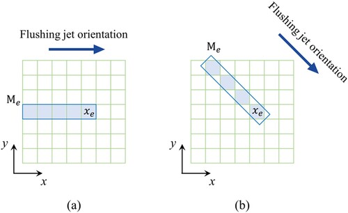
An accumulation density filter is adopted to transform the projected density field to realise the water jet accessibility, which is defined by:
(3)
(3) where
is the set of elements tracked backward the negative jet flow direction from the current element
. As shown in , the sets of accumulated elements corresponding to the horizontal and oblique jet flow directions are demonstrated as examples, e.g. all the blue-coloured elements belonging to
are added up for obtaining the accumulated density
. The length of
is related to the location of element
. Note that, the accumulation density filter can be realised through convolution operation for efficient implementation [Citation53].
Figure 3. Illustration of the set of accumulated elements.
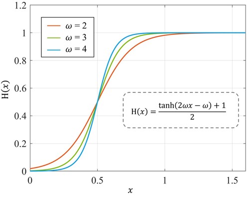
Then, a Heaviside function filter [Citation54] is used to map the accumulated density to the range of 0–1:
(4)
(4) The curves of the Heaviside function filter are plotted in . As advised in Ref. [Citation54],
= 3 is used in this paper.
Figure 4. Illustration of the Heaviside function.
shows the details of numerical processing the density field with the accessibility filter. The flow jet direction of horizontally from left to right is considered, as depicted in . gives the initial density field defined by 0 and 1. (c) is the accumulation result, in which some accumulated element densities go beyond 1. Finally, the Heaviside function is used to map the element densities back to the 0 and 1 options as demonstrated in .
Figure 5. Illustration of the water jet accessibility filter: (a) definition of the jet flow direction, (b) initialisation of the density field, (c) accumulated density field after, (d) processed density field with the Heaviside projection.
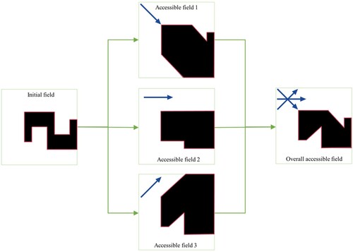
For the general cases of considering accessibility with prescribed jet flow directions, the filtered density fields can be aggregated with the P-norm function as:
(5)
(5) where
denotes the accumulated density computed from the
-th direction,
is the aggregation parameter, and
= −12 is used in this paper for the purpose of obtaining the intersection. illustrates the filtering process for accessibility with multiple jet flow directions.
Figure 6. Illustration of the filtering process for accessibility with multiple jet flow directions.
2.1.2 Interpolation functions
To accomplish the flushing jet accessibility and multi-scale topology optimisation for the LSHS, two sets of design variables are defined to represent the solid and lattice densities as:
(6)
(6)
(7)
(7) where
and
denotes the design variable collections of solid densities
and lattice densities
.
means the total number of elements.
Then, a multi-material interpolation function is utilised to describe the element properties as:
(8)
(8)
(9)
(9) where
denotes the physical element density,
is the smoothed lattice density for the
-th element.
is the element elasticity matrix.
is the elasticity matrix for a full solid element.
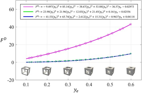
are the polynomial fitting functions describing the relationship between the effective elastic properties and the lattice relative density, referring to for the specifications.
is the penalisation factor, and we use
= 3 in this study. Note that the effective elastic properties are obtained through homogenisation-based evaluation [Citation56]. Young’s modulus and Poisson’s ratio of the base material are set as 100 and 0.3 without losing generality.
Figure 7. The fitting functions for the lattice effective elastic properties.
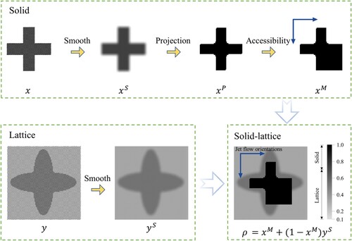
demonstrates the general idea of filtering a solid-lattice hybrid density field. Firstly, the solid and lattice design field ( and
) is smoothed to avoid mesh-dependency problem (giving
and
). Next, the smoothed solid design field
is projected to obtain a clear structural boundary (giving
). Then, the projected solid design field
is transformed for residual slurry removal with applying the accessibility filter (giving
). Here in the figure, the horizontal and vertical jet flow directions are involved. Finally, the filtered solid and lattice fields are coupled through EquationEq. (8)
(8)
(8) to define the solid-lattice field (giving
).
Figure 8. The general filtering process for a solid-lattice field with the flushing jet accessibility.
2.1.3 Intensity weakening consideration of the flushing water jet
In the previous subsections, a multi-material interpolation function is proposed to define the solid-lattice field and the filtering process is introduced to achieve the flushing jet accessibility for LSHSs. In this subsection, we further modify the accessibility filter by considering the intensity weakening effect of the flushing jet when passing through the lattices. That is, the flow intensity (or rate) of the flushing water jet decreases after passing through the porous lattices. When the flow intensity drops below some threshold, it is considered that the flushing water jet no longer has the effective cleaning ability. Therefore, the effective flushing depth of the jet flow should be included in the filter formulation and the maximum layers of lattices that the flushing water jet can pass marks the effective flushing depth. To achieve this, a straightforward numerical solution is to introduce a handle structure at the starting end of the flushing jet and include it as an augmented area for the density accumulation as depicted in . The element densities for accumulation calculation in the overlap area between the handle structure and the design domain are regarded as 1, so as to avoid the interference between the handle structure and the lattice elements after accessibility filtering. For the proposed solid-lattice design field, illustrate a density field with inaccessible areas and the filtered accessible density field with consideration of the effective flushing depth.
Figure 9. Realisation of the accessibility filtering with considering the effective flushing depth: (a) definition of the effective flushing depth, (b) an inaccessible field, and (c) the filtered accessible field.
2.2 Optimisation problem
This study considers the minimum-compliance multiscale topology optimisation problem for LSHSs under single load condition subject to an upper bound on the material volume. The topology optimisation problem is stated as:
(10)
(10) where
denotes the global structural compliance.
is the global nodal displacement vector, and
is the global stiffness matrix.
and
are the nodal displacement vector and stiffness matrix of the element.
is the force vector.
and
are the structure volume and design domain volume, respectively.
is the prescribed volume fraction limit.
The element stiffness matrix is calculated as:
(11)
(11) where
is the strain-displacement matrix,
is the element domain.
The optimisation problem (10) is solved by gradient-based method with the MMA optimiser [Citation57]. Sensitivity information of the objective and constraint functions with respect to the design variables are analyzed as follows.
2.3 Sensitivity analysis
To simplify the derivation, the sensitivities of the objective function with respect to the design variables are given by means of the chain rule [Citation58]:
(12)
(12) The term
is a standard density filter modification. Thus, only calculation of
is derived as follows.
According to the adjoint method, the sensitivity of the objective function with respect to the element design variable is:
(13)
(13) The term
is further developed based on EquationEq. (9)
(9)
(9) and (11) as:
(14)
(14) Substituting EquationEq. (5)
(5)
(5) into the term
yields:
(15)
(15)
The term in EquationEq. (15)
(15)
(15) is further developed as:
(16)
(16) Then, the term
can be derived by means of the chain rule:
(17)
(17)
The modification factor can be easily obtained with EquationEq. (3)
(3)
(3) , and the second term
can be derived from EquationEq. (2)
(2)
(2) .
Similarly, the sensitivity of the objective function with respect to is obtained as:
(18)
(18) where
(19)
(19) The derivative
can be obtained from the polynomial fitting functions.
Following the same procedures, the sensitivity of the volume constraint function can be easily derived, which is omitted here due to space limitations.
3. Numerical examples
In this section, the numerical examples of a 2D cantilever beam and a 3D MBB beam are conducted to validate the effectiveness of the proposed method. The optimisation process is implemented in MATLAB R2022b, and the MMA method [Citation57] is applied to solve the optimisation problem. The optimisation parameters are given as follows. The volume constraints for both problems are set as 0.4. The lattice density is constrained with the range between 0.1 and 0.6 given the manufacturability consideration. The move limit of MMA is set as 0.5. The sharpness parameters of the projection is gradually increased by doubling for every 50th iteration from 4 to 32. The stopping criterion of the optimisation is that the iteration number reaches 200 or the change in objective function among the last three iterations is less than 0.1%.
3.1 2D cantilever beam
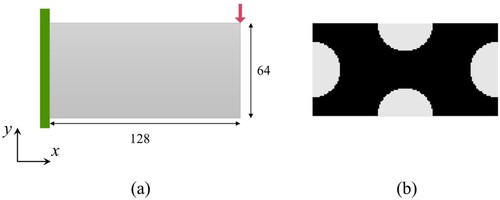
For the 2D cantilever beam example, the design domain and boundary conditions are demonstrated in . The left edge of the cantilever is fixed and a concentrated force F = 10 is applied to the upper right corner. The design domain is discretized with a 128 × 64 × 1 mesh. Specially, the mesh size in Z direction is set to 1. The initial design is given in . The filter radii for smoothing the solid design variables and the lattice design variables are set to 6 and 2.5, respectively.
Figure 10. Illustration of the 2D cantilever beam, (a) design domain and boundary conditions, (b) initial design for the optimisation.
Firstly, the flushing jet orientations are set with the positive and negative directions along both the X and Y axes, and the effective flushing depth of the jet flow equals the length of 70 layers of elements. plots the convergence history of the optimisation process with the objective structural compliance converging to 465.29. Distribution of the element-wise densities is illustrated in , and shows the reconstructed CAD model of the optimised LSHS with full structural details subject to the lattice unit size equivalent to 16 hexahedron elements. As illustrated in the figures, the overall material distribution is similar to the conventional topology optimisation result, but distinctively, the high-density lattices emerge at the top region of the optimised structure, still bearing a significant amount of load while ensuring the accessibility to the interior solids below it. In , for comparison purpose, we also optimised the 2D cantilever beam with the lattice-only optimisation method and the lattice-solid optimisation method without considering accessibility. The lattice-only optimisation result in has the final structural compliance of 689.05, while the other design including solids has an optimised structural compliance of 393.87. Apparently, the optimised design with a solid phase performs better in stiffness, but there are evidently non-reachable interior features by the pre-oriented flushing jets.
Figure 11. Iteration history of the 2D cantilever beam optimisation.
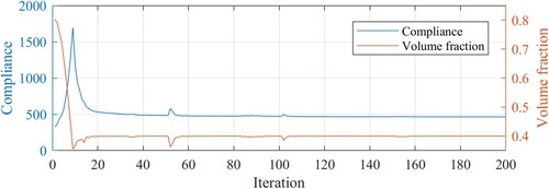
Figure 12. The optimisation results of the 2D cantilever beam with the proposed method (result compliance = 465.29): (a) distribution of the element densities, (b) reconstruction of the optimized LSHS with full structural details.
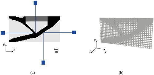
Figure 13. The comparative optimization results of the 2D cantilever beam: (a) lattice-only optimization result, (b) lattice-solid optimization result without considering flushing jet accessibility, and (c) illustration of the inaccessible regions in the lattice-solid design.
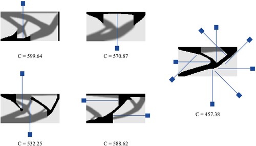
Then, the optimised designs with other flushing jet orientation options are further investigated, and the effective flushing depth of the jet flow is still set to the length of 70 layers of elements. As demonstrated in , better performing designs are achieved with increased flushing jet orientations.
Figure 14. Different optimization results with varying flushing jet orientations.
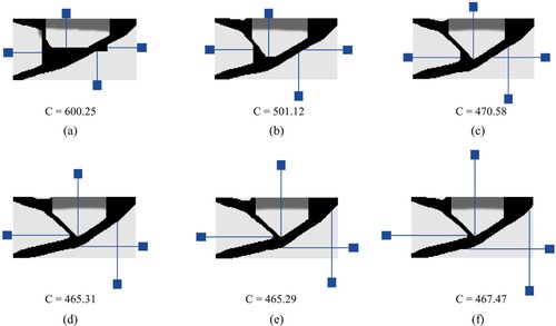
Next, the effect of flushing depth on the final optimised design is studied. The flushing jet orientation is still set with the positive and negative directions along the X and Y axes. shows the optimisation results corresponding to varying effective flushing depths. The increasing effective flushing depth from leads to a larger solution space, resulting in a decreasing trend of structural compliance. When the effective flushing depth increases to 60, the subsequent increase in depth does not take further effect in enhancing the structural performance as illustrated in . It can be seen from the figures that a flushing depth shorter than 60 has to compromise the geometric shape to move some boundaries closer to the design domain edges, that explains the associated high structural compliance. In contrast, is already the optimum solution. Having the flushing depth of 60 is sufficient to access all solid boundaries, and further increasing the flushing depth is not necessary since the backward element density accumulation of beyond 60 does not take effect.
Figure 15. The optimization results corresponding to varying effective flushing depths of the jet flow: the depth varies from (a) to (f): 30, 40, 50, 60, 70, 80.
3.2 3D MBB beam
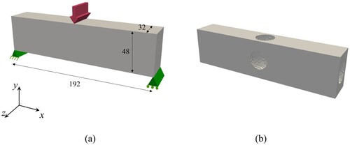
In the second example, we consider the minimum compliance optimisation problem of a 3D MBB beam. depicts the design domain and boundary conditions. The load F = 10 is homogeneously distributed along the middle line of the top surface. The two foot corners are supported to restrict zero vertical displacement. The design domain is discretized by a mesh with 192 × 48 × 32 grids. Initial guess for the design is presented in . The filtering radii for the solid and lattice design variables are set to 4 and 2, respectively.
Figure 16. Illustration of the 3D MBB beam: (a) design domain and boundary conditions, and (b) initial guess for the optimization
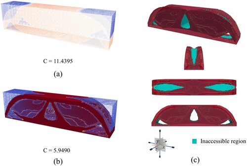
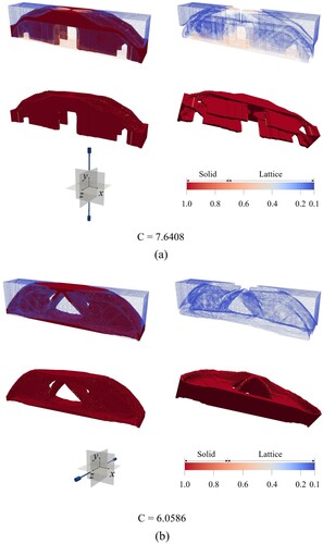
At the beginning, we set the flushing jet orientations with the positive and negative directions along the X, Y and Z axes, and the effective flushing depth equals 30 layers of elements. gives the convergence history, for which the optimisation result has the final compliance of 6.0962. demonstrates the distribution of the element-wise physical densities, and shows the reconstructed CAD model of the optimised LSHSs subject to the lattice unit size equivalent to 8, 64, and 512 hexahedron elements, respectively. The design results corresponding to multiple size mappings ensure the manufacturability under different additive manufacturing resolutions. In addition, the optimisation results from lattice-only optimisation and lattice-solid hybrid optimisation (without considering flushing jet accessibility) are presented in . Visibly in the result figures, the lattice-solid design without flushing jet accessibility performs slightly better in stiffness than our proposed design; however, there are many inaccessible regions subject to the predetermined flushing jet orientations and depth.
Figure 17. Iteration history of the 3D MBB beam optimization.
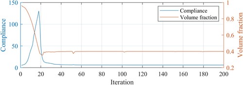
Figure 18. The optimization results of the 3D cantilever beam by using the proposed method: (a) distribution of the element-wise densities, (b) distribution of the lattice densities, (c) and (d) geometry of the solid phase.
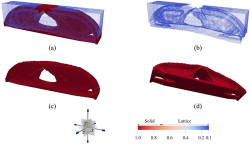
Figure 19. Reconstruction of the optimized LSHS with full structural details subject to the lattice unit size equivalent to (a) 8 hexahedron elements, (b) 64 hexahedron elements, and (c) 512 hexahedron elements.
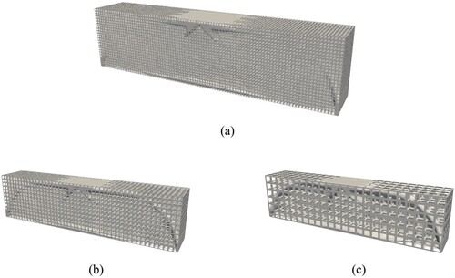
Figure 20. The comparative optimization results of the 3D cantilever beam: (a) lattice-only optimization result, (b) lattice-solid optimization result without considering the flushing jet accessibility, and (c) illustration of the inaccessible regions in the lattice-solid design.
For comparing purpose, show the optimised designs with the flushing jet orientations along the positive and negative Y-axis directions and along the positive and negative X-axis directions, respectively. The effective flushing depth in both designs is set to the length of 30 layers of elements. As demonstrated in , the high-density lattice elements in the optimisation result replace some removed solid elements for load-bearing while ensuring the water jet accessibility, but the structural performance is obviously degraded due to this replacement, indicating that the flushing jet setting has a significant effect on the structural design flexibility. For the optimisation result in , the flushing jet setting takes less effect in narrowing the design space, resulting in a very close compliance value compared with the optimisation results in and .
Figure 21. Optimization results with varying flushing jet orientations.
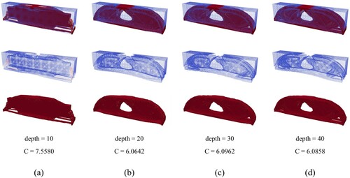
depicts the optimisation results with effective flushing depths varying from 10 to 40, for which the flushing jet orientations are fixed to the positive and negative directions along the X, Y and Z axes. It can be seen that the design space is severely perturbed when the effective flushing depth is short, like below 20, and when increased beyond 20, the influence of the flushing depth can be ignored since the compliance values in the optimisation results of fluctuate slightly with similar solid-lattice distributions.
Figure 22. The optimization results corresponding to varying effective flushing depth of the jet flow, the depth varies from (a) to (d): 10, 20, 30, 40.
4. CSL 3D printing experiment
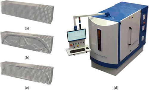
In this section, additive manufacturing and cleaning experiments for three groups of optimised 3D MBB beam models are performed to verify the effectiveness of the proposed method. shows the 3D MBB beam models with the overall structure size of 120 mm × 30 mm × 20 mm, which are (a) graded lattice infill design, LSHS designs (b) without and (c) with considering flushing accessibility constraints. The CSL 3D printer Ceramaker (3D Ceram, France) is used to print the structural details of the optimisation results as shown in . Each group of samples is printed twice to prevent accidental phenomena.
Figure 23. Experimental test on the optimized 3D MBB beam design.
Note that for flushing of the manufactured structures, the final size of the physical lattice affects the penetrability of the flushing jet. The larger size of the lattice unit leads to better penetrability of the jet flow. But according to the scale separation assumption of homogenisation, the lattice units should be evidently smaller than the part. Hence, the best resolution is to pick up the smallest lattice size that have the rods beyond the 3D printing resolution and have sufficient permeability to pass jet flow through the lattices. Hence, the lattice size of 2mm∼3 mm is recommended.
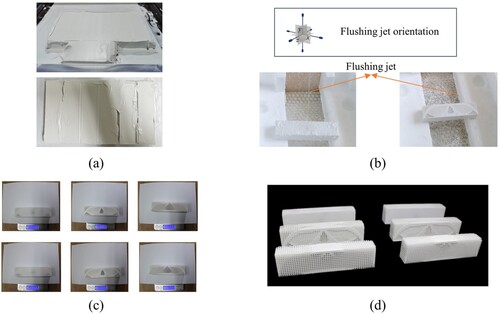
illustrates the cleaning experiment process. Firstly, the cured part bodies mixed with tremendous residual ceramic slurry are removed from the printing platform, as shown in . Then, the uncured slurry attached to the outside surface is preliminarily cleaned by a scraper. After that, the parts are flushed with water jets along the six directions (up, down, left, right, front and behind) of the parts, as shown in . The flushing time for each part in a single flushing direction is consistently 5 min. Finally, the three groups of parts after cleaning are weighed to evaluate the cleaning effect. Referring to , the weights of the six parts is 119.64, 111.43, 121.19, 122.55, 75.83 and 76.80 g, respectively. It can be found that the proposed design avoids undercut features in the solid phase due to introducing the flushing jet accessibility filter and the solid materials are concentrated in the z-axis symmetric surface of the structure. Meanwhile, due to the consideration of the effective flushing intensity of the water jet, the deep hole features are eliminated, so that the best cleaning effect has been achieved. However, the gradient lattice structure design and another LSHS design have poor cleaning results due to the appearance of deep holes and undercut structural features. Finally, the three groups of parts after cleaning are shown in .
Figure 24. Illustration of the cleaning experiment: (a) the cured part bodies are removed from the printing platform, (b) the raw part bodies are washed with water jets from the prescribed flushing orientations, (c) weigh of the three groups of parts after cleaning, and (d) demonstrate the three groups of parts after cleaning.
5. Engineering application: a pillow bracket part
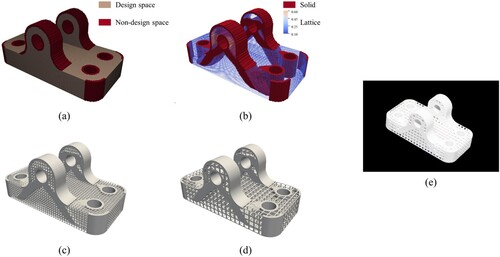
In this section, an engineering application case on pillow bracket optimisation is studied. shows the sizes and boundary conditions of the pillow bracket part. The lower mounting holes of the part are fixed, and vertical upward external forces are applied to the two upper mounting holes. The volume fraction upper limit is set to 40%. The voxelization of the part for optimisation is shown in , where the size of each hexahedral element is 1. The distribution of lattice and solid elements in the optimisation result is depicted in . The reconstructed CAD model of the optimisation result is shown in , where the lattice unit sizes equals 64 and 512 hexahedron elements, respectively. The additive manufacturing result of the optimised part are shown in .
Figure 25. Design space and boundary condition of the pillow bracket.
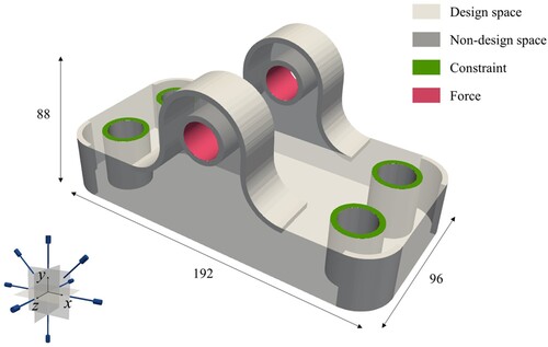
Figure 26. Optimization results of the pillow bracket: (a) the part voxelization, (b) the distribution of element densities, reconstructing the optimized part in full structural details subject to lattice unit sizes equivalent to (c) 64 hexahedron elements, (d) 512 hexahedron elements, and (e) 3D printing result of the optimized pillow bracket.
6. Conclusion
In this study, we propose a novel topology optimisation method for lattice-solid hybrid structures manufactured by ceramic vat photopolymerization 3D printing. The water jet flushing accessibility is ensured through a series of novel filtering and projection operations that enables fully removing the residual ceramic slurry. Specifically, a multi-material interpolation model for graded lattice-solid hybrid materials is proposed, which allows the density variation of lattices and the flushing jet accessibility for the solids to be treated separately. Then, several filtering and projection operations are introduced to avoid numerical issues in topology optimisation and achieve the flushing jet accessibility. The novel accessibility filter is built based on element accumulation and multiple flushing directions can be simultaneously addressed with the P-norm aggregation. Then, the multi-scale topology optimisation problem formulation for LSHSs is established and solved. Subsequently, detailed discussions are made on the numerical solution process and results of the 2D and 3D demonstration examples subject to varying flushing conditions. The effectiveness of the proposed method is verified by additive manufacturing experiments, and the results show that our proposed design achieves the best residual slurry cleaning effect.
In summary, this study proposes a novel LSHS topology optimisation method to address the difficulty in cleaning the residual ceramic slurry from the vat photopolymerization 3D printed complex parts. This study is carried out based on the cubic lattices that is friendly to flush jet cleaning. The future work will be extended to design with conformal lattice infills. In addition, incorporating stress constraints is another viable consideration.
Acknowledgements
The authors would like to acknowledge the support from The National Key Research and Development Program of China under Grant 2022YFB4601400, and the support from Shandong Provincial Key Research and Development Program (Major Scientific and Technological Innovation Project) (2021CXGC010206). The authors also would like to thank Dr. Qinghua Chen for her generous help and valuable advice in printing the components.
Disclosure statement
No potential conflict of interest was reported by the author(s).
Data availability statement
The data will be made available upon request.
Additional information
Funding
References
- Bendsøe MP, Sigmund O, Bendsøe MP., topology optimization: theory, methods, and applications. 2nd ed., corrected print Berlin Heidelberg: Springer; 2004.
- Sigmund O, Maute K. Topology optimization approaches. Struct Multidisc Optim. 2013;48:1031–1055. doi:10.1007/s00158-013-0978-6
- Huang J, Liu J. Strength constrained topology optimization of hyperealstic structures with large deformation-induced frictionless contact. Appl Math Model. 2024;126:67–84. doi:10.1016/j.apm.2023.10.032
- Wu J, Sigmund O, Groen JP. Topology optimization of multi-scale structures: a review. Struct Multidisc Optim. 2021;63:1455–1480. doi:10.1007/s00158-021-02881-8
- Panesar A, Abdi M, Hickman D, et al. Strategies for functionally graded lattice structures derived using topology optimisation for additive manufacturing. Additive Manuf. 2018;19:81–94. doi:10.1016/j.addma.2017.11.008
- Zhang C, Xu S, Liu J, et al. Comprehensive clustering-based topology optimization for connectable multi-scale additive manufacturing structures. Additive Manuf. 2022;54:102786. doi:10.1016/j.addma.2022.102786
- Li H, Luo Z, Gao L, et al. Topology optimization for concurrent design of structures with multi-patch microstructures by level sets. Comput Methods Appl Mech Eng. 2018;331:536–561. doi:10.1016/j.cma.2017.11.033
- Zhou Y, Gao L, Li H. Topology optimization design of graded infills for 3D curved volume by a conformal sweeping method. Comput Methods Appl Mech Eng. 2023;412:116009. doi:10.1016/j.cma.2023.116009
- Osanov M, Guest JK. Topology optimization for architected materials design. Rev Mater Res. 2016;46:211–233. doi:10.1146/annurev-matsci-070115-031826
- Wang F, Brøns M, Sigmund O. Non-hierarchical architected materials with extreme stiffness and strength. Adv Funct Mater. 2023: 2211561. doi:10.1002/adfm.202211561
- Liu J, Gaynor AT, Chen S, et al. Current and future trends in topology optimization for additive manufacturing. Struct Multidisc Optim. 2018;57:2457–2483. doi:10.1007/s00158-018-1994-3
- Zhu J, Zhou H, Wang C, et al. A review of topology optimization for additive manufacturing: status and challenges. Chin J Aeronaut. 2021;34:91–110. doi:10.1016/j.cja.2020.09.020
- Plocher J, Panesar A. Review on design and structural optimisation in additive manufacturing: towards next-generation lightweight structures. Mater Des. 2019;183:108164. doi:10.1016/j.matdes.2019.108164
- Pellens J, Lombaert G, Lazarov B, et al. Combined length scale and overhang angle control in minimum compliance topology optimization for additive manufacturing. Struct Multidisc Optim. 2019;59:2005–2022. doi:10.1007/s00158-018-2168-z
- Xu S, Liu J, Li X, et al. A full-scale topology optimization method for surface fiber reinforced additive manufacturing parts. Comput Methods Appl Mech Eng. 2022;401:115632. doi:10.1016/j.cma.2022.115632
- Liu J, Zheng Y, Ahmad R, et al. Minimum length scale constraints in multi-scale topology optimisation for additive manufacturing. Virtual Phys Prototyp. 2019;14:229–241. doi:10.1080/17452759.2019.1584944
- Cheng L, Bai J, To AC. Functionally graded lattice structure topology optimization for the design of additive manufactured components with stress constraints. Comput Methods Appl Mech Eng. 2019;344:334–359. doi:10.1016/j.cma.2018.10.010
- Wang C, Gu X, Zhu J, et al. Concurrent design of hierarchical structures with three-dimensional parameterized lattice microstructures for additive manufacturing. Struct Multidisc Optim. 2020;61:869–894. doi:10.1007/s00158-019-02408-2
- Xiao M, Liu X, Zhang Y, et al. Design of graded lattice sandwich structures by multiscale topology optimization. Comput Methods Appl Mech Eng. 2021;384:113949. doi:10.1016/j.cma.2021.113949
- Clausen A, Wang F, Jensen JS, et al. Topology optimized architectures with programmable Poisson's ratio over large deformations. Mater. 2015;27:5523–5527. doi:10.1002/adma.201502485
- Garner E, Kolken HMA, Wang CCL, et al. Compatibility in microstructural optimization for additive manufacturing. Additive Manufacturing. 2019;26:65–75. doi:10.1016/j.addma.2018.12.007
- Guest JK, Prévost JH, Belytschko T. Achieving minimum length scale in topology optimization using nodal design variables and projection functions. Int J Numer Meth Eng. 2004;61:238–254. doi:10.1002/nme.1064
- Wang F, Lazarov BS, Sigmund O. On projection methods, convergence and robust formulations in topology optimization. Struct Multidisc Optim. 2011;43:767–784. doi:10.1007/s00158-010-0602-y
- Liu J. Piecewise length scale control for topology optimization with an irregular design domain. Comput Methods Appl Mech Eng. 2019;351:744–765. doi:10.1016/j.cma.2019.04.014
- Zhang W, Li D, Zhang J, et al. Minimum length scale control in structural topology optimization based on the moving morphable components (MMC) approach. Comput Methods Appl Mech Eng. 2016;311:327–355. doi:10.1016/j.cma.2016.08.022
- Xu S, Liu J, Huang J, et al. Multi-scale topology optimization with shell and interface layers for additive manufacturing. Additive Manuf. 2021;37:101698. doi:10.1016/j.addma.2020.101698
- Groen JP, Sigmund O. Homogenization-based topology optimization for high-resolution manufacturable microstructures. Int J Numer Meth Eng. 2018;113:1148–1163. doi:10.1002/nme.5575
- Qiu Z, Li Q, Liu S, et al. Clustering-based concurrent topology optimization with macrostructure, components, and materials. Struct Multidisc Optim. 2021;63:1243–1263. doi:10.1007/s00158-020-02755-5
- Zhang C, Liu J, Yuan Z, et al. A novel lattice structure topology optimization method with extreme anisotropic lattice properties. J Comput Des Eng. 2021;8:1367–1390. doi:10.1093/jcde/qwab051
- Xu S, Liu J, Ma Y. Residual stress constrained self-support topology optimization for metal additive manufacturing. Comput Methods Appl Mech Eng. 2022;389:114380. doi:10.1016/j.cma.2021.114380
- Liu J, Huang J, Zheng Y, et al. Challenges in topology optimization for hybrid additive–subtractive manufacturing: A review. Computer-Aided Des. 2023;161:103531. doi:10.1016/j.cad.2023.103531
- Zhao D, Gu TT, Liu Y, et al. Constructing self-supporting structures in biscale topology optimization. Vis Comput. 2022;38:1065–1082. doi:10.1007/s00371-021-02068-8
- Wang W, Feng D, Yang L, et al. Topology optimization of self-supporting lattice structure. Additive Manuf. 2023;67:103507. doi:10.1016/j.addma.2023.103507
- Luo Y, Sigmund O, Li Q, et al. Topology optimization of structures with infill-supported enclosed voids for additive manufacturing. Additive Manuf. 2022;55:102795. doi:10.1016/j.addma.2022.102795
- Clausen A, Aage N, Sigmund O. Exploiting additive manufacturing infill in topology optimization for improved buckling load. Eng. 2016;2:250–257. doi:10.1016/J.ENG.2016.02.006
- Liu H, Chen L, Jiang Y, et al. Multiscale optimization of additively manufactured graded non-stochastic and stochastic lattice structures. Compos Struct. 2023;305:116546. doi:10.1016/j.compstruct.2022.116546
- Lee H, Lim CHJ, Low MJ, et al. Lasers in additive manufacturing: A review. Int J Precis Eng Manuf-Green Tech. 2017;4:307–322. doi:10.1007/s40684-017-0037-7
- Balčas G, Malinauskas M, Farsari M, et al. Fabrication of glass-ceramic 3D micro-optics by combining laser lithography and calcination. Adv Funct Mater. 2023: 2215230. doi:10.1002/adfm.202215230
- Liu S, Li Q, Chen W, et al. An identification method for enclosed voids restriction in manufacturability design for additive manufacturing structures. Front Mech Eng. 2015;10:126–137. doi:10.1007/s11465-015-0340-3
- Zhou L, Zhang W. Topology optimization method with elimination of enclosed voids. Struct Multidisc Optim. 2019;60:117–136. doi:10.1007/s00158-019-02204-y
- Schwarzer E, Götz M, Markova D, et al. Lithography-based ceramic manufacturing (LCM) – viscosity and cleaning as two quality influencing steps in the process chain of printing green parts. J Eur Ceram Soc. 2017;37:5329–5338. doi:10.1016/j.jeurceramsoc.2017.05.046
- Sobhani S, Allan S, Muhunthan P, et al. Additive manufacturing of tailored macroporous ceramic structures for high-temperature applications. Adv Eng Mater. 2020;22:2000158. doi:10.1002/adem.202000158
- Paredes C, Martínez-Vázquez FJ, Elsayed H, et al. Evaluation of direct light processing for the fabrication of bioactive ceramic scaffolds: effect of pore/strut size on manufacturability and mechanical performance. J Eur Ceram Soc. 2021;41:892–900. doi:10.1016/j.jeurceramsoc.2020.09.002
- Xing Z, Zhou H, Liu W, et al. Efficient cleaning of ceramic green bodies with complex architectures fabricated by stereolithography-based additive manufacturing via high viscoelastic paste. Additive Manuf. 2022;55:102809. doi:10.1016/j.addma.2022.102809
- Zhang G, Zou B, Wang X, et al. Design, manufacturing and properties of controllable porosity of ceramic filters based on SLA-3D printing technology. Ceram Int. 2023;49:1009–1019. doi:10.1016/j.ceramint.2022.09.076
- Zhang C, Wu T, Xu S, et al. Multiscale topology optimization for solid–lattice–void hybrid structures through an ordered multi-phase interpolation. Computer-Aided Des. 2023;154:103424. doi:10.1016/j.cad.2022.103424
- Kim J-E, Park K. Multiscale topology optimization combining density-based optimization and lattice enhancement for additive manufacturing. Int J Precis Eng Manuf-Green Tech. 2021;8:1197–1208. doi:10.1007/s40684-020-00289-1
- Halloran JW. Ceramic stereolithography: additive manufacturing for ceramics by photopolymerization. Rev Mater Res. 2016;46:19–40. doi:10.1146/annurev-matsci-070115-031841
- Chen Q, Zou B, Lai Q, et al. Influence of irradiation parameters on the curing and interfacial tensile strength of HAP printed part fabricated by SLA-3D printing. J Eur Ceram Soc. 2022;42:6721–6732. doi:10.1016/j.jeurceramsoc.2022.07.019
- Mao H, Jia W, Leung Y-S, et al. Multi-material stereolithography using curing-on-demand printheads. Rapid Prototyp J. 2021;27:861–871. doi:10.1108/RPJ-05-2020-0104
- Zhou C, Chen Y, Yang Z, et al. Digital material fabrication using mask-image-projection-based stereolithography. Rapid Prototyp J. 2013;19:153–165. doi:10.1108/13552541311312148
- Langelaar M. Topology optimization for multi-axis machining. Comput Methods Appl Mech Eng. 2019;351:226–252. doi:10.1016/j.cma.2019.03.037
- Mirzendehdel AM, Behandish M, Nelaturi S. Topology optimization with accessibility constraint for multi-axis machining. Computer-Aided Des. 2020;122:102825. doi:10.1016/j.cad.2020.102825
- Deng H, To AC. A novel mathematical formulation for density-based topology optimization method considering multi-axis machining constraint. J Mech Des. 2022;144:061702. doi:10.1115/1.4053333
- Sigmund O. Morphology-based black and white filters for topology optimization. Struct Multidisc Optim. 2007;33:401–424. doi:10.1007/s00158-006-0087-x
- Gao J, Li H, Gao L, et al. Topological shape optimization of 3D micro-structured materials using energy-based homogenization method. Adv Eng Software. 2018;116:89–102. doi:10.1016/j.advengsoft.2017.12.002
- Svanberg K. The method of moving asymptotes—a new method for structural optimization. Int J Numer Meth Eng. 1987;24:359–373. doi:10.1002/nme.1620240207
- Andreassen E, Clausen A, Schevenels M, et al. Efficient topology optimization in MATLAB using 88 lines of code. Struct Multidisc Optim. 2011;43:1–16. doi:10.1007/s00158-010-0594-7