
 ?Mathematical formulae have been encoded as MathML and are displayed in this HTML version using MathJax in order to improve their display. Uncheck the box to turn MathJax off. This feature requires Javascript. Click on a formula to zoom.
ABSTRACT
Additive manufacturing in construction typically consists of ground-based platforms. Introducing aerial capabilities offers scope to create or repair structures in dangerous or elevated locations. The Aerial Additive Manufacturing (AAM) project has developed a pioneering approach using Unmanned Aerial Vehicles (UAV, ‘drones’) to deposit material during self-powered, autonomous, untethered flight. This study investigates high and low-density foams autonomously deposited as structural and insulation materials. Drilling resistance, mechanical, thermal and microscopy tests investigate density variation, interfacial integrity and thermal stability. Autonomous deposition is demonstrated using a flying UAV and robotic arm. Results reveal dense material at interfaces and directionally dependent cell expansion during foaming. Cured interfacial regions are vulnerable to loading parallel to interfaces but resistant to perpendicular loading. Mitigation of trajectory printing errors caused by UAV flight disturbance is demonstrated by a stabilising end effector, with trajectory errors ≤10 mm. AAM provides a significant development towards on-site automation in construction.
Highlights
Aerial Additive Manufacturing (AAM) releases additive manufacturing (AM) for construction applications from ground-based and tethered restraints.
Multiple self-powered flying Unmanned Aerial Vehicles (UAV) can deposit layers of polyurethane foam in planned trajectories.
High-density polyurethane foam and low-density foam can be suitable for structural and insulating layers, respectively.
Laboratory tests, including drilling resistance, demonstrate the high-density of interfacial boundary regions in relation to material located away from a boundary.
The challenges of reducing lateral deformation of extruded material are evaluated, and improved flight stabilisation provided by an end effector keeping trajectory errors within 10 mm is demonstrated.
ABBREVIATIONS:
- AAM: Aerial Additive Manufacturing
- AM: Additive Manufacturing
- DMA: Dynamic Mechanical Analysis
- DoF: Degrees of Freedom
- DSC: DifferentialScanning Calorimetry
- E': Elastic/storage modulus (DMA)
- E”: Viscous/loss modulus(DMA)
- FTIR: Fourier Transform Infrared Spectroscopy
- G': Elastic/storage modulus(Rheology)
- G”: Viscous modulus (Rheology) nm: Nanometres
- PSD: Position Sensitive Detector
- STA: Simultaneous ThermalAnalysis
- TGA: Thermal Gravimetric Analysis
- Tan δ: Damping factor (DMA)
- UAV:Unmanned Aerial Vehicle
- Vf: Volume fraction
- XRD: X-Ray Diffraction
- δ: PhaseAngle
1. Introduction
Additive Manufacturing (AM) has much to offer the construction industry, such as promoting efficiency, reducing construction time and increasing automation which reduces safety risks [Citation1]. However, AM methods are still in a state of relative infancy in the construction industry and typically consist of large, ground-based deposition methods [Citation2, Citation3], although the development of digital technologies in the construction industry is ongoing [Citation4], and new projects are emerging regularly [Citation5]. The AM principal of fused deposition modelling to extrude material is commonly used in construction-related AM studies. As a result of extrusion, which deposits material through a nozzle in a series of layers [Citation6, Citation7], a series of interfacial regions is created within the material. In addition to manufacturing parameters such as the height of the printed layer and the speed of deposition [Citation2, Citation3], the adhesive, rheological, and expansion properties of a curing material affect these interfacial regions, with the density of the cured material being important to the integrity of the resulting building.
Current state-of-the-art in construction-related AM comprehends three main types of robotic platforms: gantries, robotic arms, and mobile robots. Although the off-site deployment of these systems brings more precision, quality and safety improvements because of the protected and optimised indoor environment [Citation8], the high transportation costs and CO emissions create a tendency for their use in on-site applications [Citation9–13]. To overcome the scalability limitations of the monolithic systems regardless of their location, deploying a swarm of small mobile robots [Citation14, Citation15] that is inspired by the builders in nature entails research endeavours in several methodologies like assembly [Citation16–18], tensile structuring [Citation19–21], and additive manufacturing [Citation22–26]. However, all these systems have predefined building canvases restricted by their hardware and tethers that cause different problems of tangling or collision [Citation27] and necessitate the navigation in, on, or around the built structure and adaptation to the existing terrain.
Introducing aerial capabilities to AM with the aim of releasing building projects from dimensional and topographic restrictions is a novel perspective known as ‘Aerial Additive Manufacturing (AAM)’. It is a pioneering study involving the development of an aerial platform, using unmanned aerial vehicles (UAV, commonly referred to as ‘drones’) equipped with a custom manipulator to autonomously deposit material in the fresh state on the fly and free of tethering. This creates a paradigm shift in the use of aerial robots in the construction industry, which previously consisted of surveillance and inspection [Citation28, Citation29], and opens up more deployment of these agents in this industry similar to military, civilian, commercial and emergency service sectors [Citation30]. AAM also enables agile repair and construction tasks at significant heights. Construction industry fatalities occur mostly due to falls from height [Citation31–33] and AAM would reduce requirements for dangerous height-based activities.
Polyurethane foam is a versatile material available in a wide range of densities. As density increases, the extent to which the curing liquid material expands prior to solidification is decreased. Polyurethane foam possesses a low coefficient of thermal conductivity [Citation34]. High expansion, low-density foam is established in the construction industry as an insulating material [Citation35] and has been investigated in AM construction-related applications. A study by the University of Quebec, Canada, introduced a cable-suspended robotic printer with six degrees of freedom 3D-printing polyurethane foam [Citation36, Citation37]. The Batiprint 3D project at the University of France, Nantes used expanding polyurethane foam to create formwork for concrete casting in the construction of a large house [Citation38, Citation39] and low-density, high expanding foam printed as formwork can also serve as insulation. Low-density foam was used by [Citation40] to realise a circular structure of 14.6 m diameter and 3.7 m height, and polyurethane foam has been used as a secondary material to infill elements of a lattice structure with thermoplastic polyurethane as the primary material [Citation41]. The Canal House and Urban Cabin projects, designed by DUS architects and located in Amsterdam, the Netherlands, are examples of polymeric materials being used with a ground-based fused deposition method to 3D print habitable structures [Citation42, Citation43].
The feasibility of using an aerial robot to 3D print low-density polyurethane foam in-situ during a controlled flight has been demonstrated [Citation44], with foam being pushed into a mixing nozzle and stored for 90 seconds in a mixing chamber for the right amount of curing before being printed. AAM research was further progressed by increasing printing precision with a manipulator and expanding material possibilities with the investigation of various densities of polyurethane foam [Citation45–49]. While printing precision was initially reported as being within a 10 cm radius [Citation44], Chermprayong et al. [Citation45] later demonstrated a major advance in precision, with tolerances decreasing to a maximum of 20 mm in radius. Zhang et al. [Citation50] further demonstrated the deposition of both cementitious material and polyurethane foam material from multiple UAV agents flying in pre-defined trajectories with multiple agents aware of the movement of other agents and locations of previously deposited material, with foam deposited in a layered cylindrical structure in excess of a metre tall. illustrates the conceptual vision of multiple UAV agents autonomously depositing foam material in layers with complex trajectories.
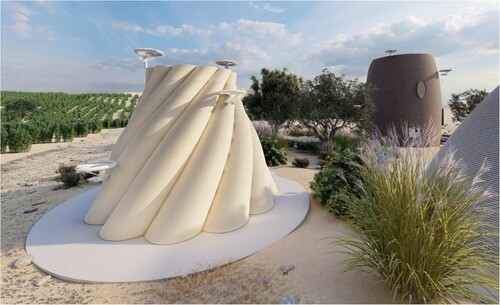
Figure 1. The conceptual vision of Aerial Additive Manufacturing (AAM) depicting multiple self-powered and untethered unmanned aerial vehicles (UAV) extruding fresh foam material in defined layers with planned trajectories to form structures on-site.
This study builds upon the work of [Citation50] by further examining the feasibility of an AAM foam solution using high-density, low expanding polyurethane foams to create or repair a habitable structure, envisaging high-density foam as structural layers and low-density foam as insulating layers. To the authors' knowledge, high-density, low-expanding polyurethane foam has not previously been used as a material in the construction industry, whether in conjunction with AM applications or not. It has previously been demonstrated by the authors that high-density polyurethane foam has the potential to be a structural material, with compressive strengths exceeding 30 MPa [Citation48]. Interfacial regions define the performance of AM components. For the first time, this study examines interfacial and external edge boundary regions for high and low-density foams by investigating material density both at interfaces within the material and at boundaries imposed by moulds, which represent the presence of supporting material. Drilling, mechanical, thermal and microscopy tests are used. Cured specimen failure modes relating to interfaces during mechanical tests are investigated. The challenges to mitigate lateral deformation of extruded fresh material and for a deposition device to extrude a curing material are considered. The further task of minimising imperfections in layer printing with the mitigation of errors caused by flight disturbance through an approach of stabilisation is investigated and evaluated. Suitable potential construction applications, with implications for AAM architectural and structural design, are discussed.
2. Experimental methodology
Both low-density and high-density closed cell thermosetting rigid polyurethane foams were investigated in this study. Foam consisted of two liquid components -- a polyol diol resin and diphenylmethane di-isocyanate hardening agent [Citation51]. Upon polymerisation of the liquid components, a cross-linked rigid foam was formed [Citation52] through a gel reaction and competing blow reaction [Citation53]. For the blow reaction, water present in the mixture served as a blowing agent, and no additional chemical or physical blowing agents were added. The rheology properties of the high-density and low-density foams used have been previously tested by the authors and the reader is referred to [Citation48] for further information on the oscillation and flow tests conducted upon the freshly mixed material and individual liquid components.
shows typical applications of three different cured foams [Citation48, Citation54], along with the average density of ten laboratory-manufactured test specimens and the resulting volume fraction Vf of the polymer matrix given by:
(1)
(1) where
is the laboratory-determined density of the cured foam specimen and
is the density of solid polyurethane, taken as 1200 kg/m
[Citation55]. Using the rheological methodology outlined in [Citation48], expansion ratios were attained using a Malvern Pro+ rheometer, which monitored and maintained normal force as the mixed liquid components expanded between the parallel upper and lower plates.
Table 1. Types of Polyurethane foam used in this study.
2.1. Polyurethane foam test specimen manufacture
During specimen manufacture, the laboratory environment was 21
C with 52% air humidity ±5%. Prior to 1:1 mixing by volume, the individual liquid components of the foam were heated to 35
C
C and the exothermic reaction resulted in a cured, rigid specimen at 180 seconds with rapid solidification commencing at 170 seconds. Two methods were employed to manufacture the laboratory test specimens.
Method one consisted of cut-edged specimens with an internal interface. For all three foams, the two liquid components were poured into a tray and hand mixed to create a bulk of material from which test specimens were cut to size with an electric band saw. Due to the requirement to make multiple specimens for mechanical and drilling tests, the logistical necessity to respect laboratory timescales and the schedules of shared facilities informed the decision to make large batches of foam in trays rather than individually print test specimens. The liquid components were mixed and poured in two deposition cycles:
Firstly, enough liquid was mixed and poured to occupy half of the tray volume.
After curing for three minutes, a second quantity of liquid was mixed and poured on top of the cured layer to fill the remainder of the tray.
Preliminary mechanical tests varied the time period between layer deposition using three, fifteen and thirty minutes. These revealed no discernible difference in results, as the material was fully cured after three minutes. Additionally, within a time period of less than three minutes, the first layer stays still liquid-like and incapable of receiving a defined second layer. Consequently, the time between layer deposition was kept consistent at three minutes throughout this study.
The second method consisted of manufacturing moulded, one-layered specimens. The mould represented the presence of a 3D-printed supporting material deposited using a suitable technique for fused deposition modelling-based AM, such as the shell or film techniques [Citation36]. For all foams:
The two liquid components were hand-mixed in a measuring beaker.
The mixed liquid was poured into wooden moulds, which had been pre-treated using wood sealant and Macsil releasing agent to act as a barrier and prevent the foam from bonding to the mould surface.
The mixed liquid expanded and cured within the moulds. Enough liquid was poured in to fully occupy the mould volume; therefore, these specimens had no internal interface.
Initial tests examining the flexural strength of moulded cured specimens, made using both hand mixing and a dual syringe deposition device with tubing and a static mixer light enough to be carried by an aerial robot [Citation48], showed no discernible differences in results between the two methods. Therefore, a continuation of the hand-mixing method was considered appropriate for this study.
Using an infrared digital thermometer, the mean temperatures recorded during the contained foaming reactions were 108C for high-density Reprocell 500, 78
C for medium-density Reprocell 300 and 46
C for low-density LD40. These were much higher than the temperature of a mixed liquid component foaming reaction deposited onto a level, free surface at room temperature with no containment, typically ≈50
C for Reprocell 500 and less for Reprocell 300 and LD40 foams.
2.2. Cured thermal stability
To verify the glass transition temperature of the foam, Dynamic Mechanical Analysis (DMA) was carried out upon cured powdered samples. DMA was carried out using a Mettler Toledo DMA1 instrument with star system analysis software over a temperature range of 30C to 450
C with a ramp of 5
C/minute. A solid cube specimen of each cured foam measuring
was clamped in compression geometry with a 1 N pre-load. Force was applied to realise a displacement of 0.01 mm (0.2% strain), and oscillations were kept constant at 1 Hz. DMA measured the storage modulus E' and the loss modulus E”, both quantification of the rigidity of the material, along with the damping factor, tan (δ), with the resulting reductions in E' and visible peaks observed in tan (δ) indicating the occurrence of glass transition.
2.3. Drilling resistance
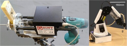
To examine the variation in density within the cured foam, the drilling resistance of the specimens was measured using a Sint Technology cordless drilling resistance measurement system (DRMS) fitted with a 5 mm diameter polycrystalline diamond flat-tipped drill bit. The position of the drill bit was linked to software which continuously recorded the force required to advance the penetration of the moving drill bit through the foam specimen. The DRMS device was affixed to a steel frame and positioned on a tripod, as shown in (left). The steel frame allowed for forward and backward adjustment to position the drill bit 1 mm from the sample prior to commencing autonomous drilling. Two steel plates linked with threads allowed foam specimens to be clamped using wing nuts.
Figure 2. Left: The SINT Technology drilling resistance measurement system (DRMS) (a) drilled test specimen. (b) clamp. (c) drill bit. (d) tripod attachment. (e) DRMS module connected to the software. (f) drill. Right: The Dobot magician Robot arm, with mixed foam in the fresh state passing through the tubing nozzle and deposited upon a level surface (g).
The rectangular parallelepiped specimens measured 220 mm long × 50 mm wide × 25 mm deep. The bit rotation speed was 300 rpm, and the bit penetration speed (or rate of advancement) was kept at 10 mm/min with a total advancement distance set at 30 mm, allowing bit penetration through the entire body of the 25 mm deep specimens. The foam material is non-homogeneous and contains variations in pore size [Citation48]. Therefore, both moulded one-layered specimens and cut-edge specimens with horizontal interfaces were drilled three times in differing locations and mean values were taken. To monitor the drill bit wear, holes were drilled into a homogeneous reference material at intervals of one hour to ensure a consistent force was required for the penetration of the reference material and that drilling results were not compromised by the increased temperature or wear of the drill bit.
2.4. Modes of failure
Shear tests were conducted on rectangular parallelepiped specimens of all three foams with the same dimension as those used for drilling resistance. shows the steel shear test rig, assembled in accordance with BS ISO 1922:2012 [Citation56], containing a low-density LD40 polyurethane foam specimen. The lower plate (attached to the machine grip on the right of ) was fixed, and the upper plate was moved away from the base plate as indicated, applying shear stress to the specimen.
Figure 3. The shear stress test rig (a) movable machine grip. (b) universal joint connections, allowing axis rotation. (c) tongue and grooves. (d) nut and bolt support with load spreading plates. (e) supporting steel plates with sandblasted internal surfaces. (f) test parallelepiped specimen , bonded with adhesive to the steel plates. (g) fixed machine grip.
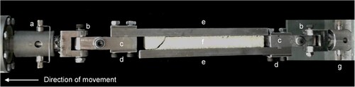
Smooth steel plate surfaces were uniformly roughened before specimen adhesion by grit-blasting with recycled glass particles. Prior to testing, imperfections on the surfaces of moulded specimens were sanded with abrasive paper, and the specimens were bonded to the plates with an adhesive. Once bonded, the specimens were left to cure for 24 hours at a temperature of 100C to fully harden the adhesive and encourage a cohesive failure within the internal interface. During the shear tests, specimens with interfaces experienced loading parallel to the interface.
Three-point flexural strength tests have previously been conducted by the authors on 350 mm long × 50 mm wide × 25 mm deep rectangular parallelepiped specimens of LD40, Reprocell 300 and Reprocell 500 foam in accordance with BS 4370-4:1991 [Citation57] using a 50 kN Instron Universal 2630-120/305632 device [Citation48]. This study focuses on the modes of flexural failure for specimens containing an internal horizontal interface perpendicular to the direction of loading and evaluates whether the interface was a region of strength or weakness.
2.5. Scanning electron microscopy
A JEOL 247 SEM6480LV scanning electron microscope was used to obtain images of cured foam specimens at magnifications of ×10 and ×22 to qualitatively assess cell structure, density variation and the extent of cell anisotropy. The specimens were covered with a 10 nm gold coating immediately prior to insertion into the SEM chamber in order to reduce charging.
2.6. Autonomous deposition of fresh material and representative trajectories error with end effector
Separate experiment phases were conducted to demonstrate the extrusion of polyurethane foam by a deposition agent -- foam extrusion using a robotic arm and mixed high-density, low expansion foam liquid components passing through tubing, extrusion by hand to test the chosen low-density, high expansion sprayed foam material and circular trajectory and finally deposition of the sprayed low-density foam using the aerial platform. Inherently, there is variation in layer height of printed expanding foam; this is more pronounced with lower-density, higher expanding foam.
A dual syringe motorised deposition device with tubing and a static mixer, the hardware of which is fully detailed in [Citation48], was used to deposit freshly mixed foam. The device consisted of two Plastipak 50 ml concentric luer lock syringes with the two liquid components separate in each syringe. 3 mm internal diameter silicone rubber tubes would take the liquid components and with a 2 to 1 connector, the two components would then mix in a single 5 mm internal diameter tube containing two 5 mm static epoxy mixing nozzles. The curing process of the mixed foam dictated the length of tubing used. The capabilities of the motor resulted in a 170 mm length of tubing equating to a duration of one minute for the mixed foam to progress along the tubing. The length of tubing therefore was designed at 34 mm to allow two minutes and then the curing reaction resulting in solidification as soon as possible following deposition. Naturally, the plastic tubing and epoxy mixers would have to be treated as disposable using this method as used items contained the last remaining liquid, which would fully cure. The tubing nozzle was manipulated in 3D space by a Dobot magician robotic arm (as shown in right) with four degrees of freedom and programmable trajectory. Multiple layers were extruded, in the formation of an arc, by the robotic arm onto a level surface in immediate succession to examine lateral deformation and evaluate the challenge presented by the fresh, uncured properties of the material to an AAM construction approach.
The aerial platform, designed explicitly for AAM high-payload construction tasks, consists of two main modules: a flying base and a parallel robot. The flying base is actuated by a coaxial tricopter UAV consisting of 6 brushless DC motors. The parallel manipulator includes three servo motors in delta robot configuration to achieve three Degrees of Freedom (DoF) movements on three translational axes to compensate for the tracking errors. The UAV robot hosts an Nvidia Jetson TX2 onboard computer and the Pixhawk 4 flight controller. The system is tested in a motion capture system, and onboard sensing is also tested, which is based on Lidar. As a proof-of-concept vehicle for AAM, a series of flight tests in a linear trajectory was performed mimicking the tracking behaviour of a mobile printer to assess the improvement in compensating for trajectory errors which can be caused by disturbances during flight such as wind gusts and a changing centre of gravity. Expanding polyurethane foam has been demonstrated as being suitable for ground-based extrusion of a dome-shaped print on an architectural scale [Citation40]. Test extrusions using polyurethane foam suitable for AAM deposition were conducted in a fully circular trajectory to facilitate multiple layer extrusion in a closed structure and the versatility offered by an aerial approach. Flight tests were also conducted in a planned circular trajectory in which the aerial platform extruded fresh polyurethane foam material during flight. The low-density foam in these prints mixed components from two cans and spraying through the nozzle occurred immediately following mixing, with expansion occurring on the printing surface.
A complete aerial 3D printing system should be able to receive a sliced model for printing with a defined printing site from an operator and perform all associated flight planning for multiple printing agents autonomously. Currently, a system has been implemented that can take print layer trajectories in a specific format, transform these to a desired location and execute a print with a single drone. Future work will be required to extend this to planning with multiple agents, including mapping and collision avoidance for operation in unstructured environments incorporating structural integrity assessment and making corrections to the print as it progresses.
The printing software uses Robot Operating System (ROS) middleware running on Ubuntu 20.01 LTS to facilitate communication between the companion computer onboard the drone, the PX4 flight controller and a ground station computer. This pipeline is well documented [Citation58] and so this paper will focus on the specific requirements of operating an aerial vehicle with a manipulator in an aerial manufacturing context.
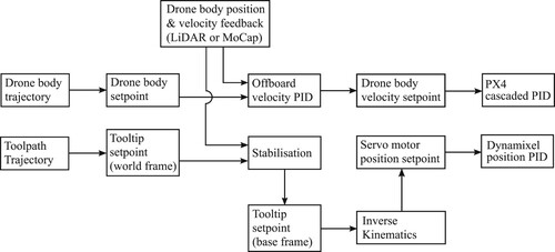
The system takes a toolpath trajectory as an input and transforms this to find a corresponding offset drone trajectory. It can also accept independent drone body and tooltip trajectories. This may be useful in future work printing complex geometry to provide a fast-moving tooltip trajectory and a smoothed drone body trajectory to minimise pitch and roll disturbances. shows the process of generating setpoints for the onboard PX4 flight controller and servo motors based on input reference trajectories and position feedback.
Figure 4. Diagram to demonstrate generation of setpoints for the servo motors and PX4 flight controller with inputs of position and velocity estimates and reference drone and tooltip trajectories.
3. Results and discussion
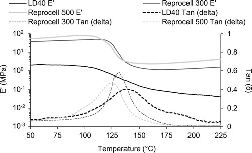
3.1. Cured thermal stability
The DMA illustrated in shows the storage modulus E' (on a logarithmic scale) and damping factor tan (δ) (loss modulus E” divided by E') for the three foam samples (one sample for each foam). The tan (δ) peaks of the LD40 foam samples were significantly broader than those of the Reprocell foams, but all foams show glass transition within the temperature range of 120C–150
C. LD40 displays a significantly lower storage modulus than the Reprocell foams, confirming it is a much less-stiff material. indicates a glass transition temperature within the range 120
C–150
C. DMA evaluated the thermal integrity of the cured polyurethane foam and demonstrated the material as being thermally stable below 100
C.
Figure 5. DMA for solid cuboid samples of the three foams showing storage modulus E' (on a log scale) and damping factor tan (δ), with results showing glass transition temperatures in the range of 120C–150
C.
3.2. Drilling resistance
The results of the drilling resistance measurements are presented in . The moulded, one-layered specimens show a higher force was required at the beginning and the end of the drilling process. In contrast, the two-layered cut-edged horizontal interface specimens display higher force in the centre. The three graphs feature differing y-axes due to the changing levels of force required for the drill bit to penetrate the material, with less than 2.5 N required for the densest areas of LD40 foam ((a)) ranging to almost 40 N to penetrate dense boundary areas of Reprocell 500 specimens ((c)). As the density of the foam increased and expansion decreased, the extra force required to penetrate the material at the interface of two-layered cut-edged specimens declined. With the low-density and high expanding LD40 ((a)), only ≈5% of the force required to penetrate the foam at the internal interface was required to penetrate foam away from the interface. This changes to ≈50% of the interfacial force required for Reprocell 300 ((b)) and ≈85% for Reprocell 500 ((c)).
Figure 6. Drilling resistance for the foams (a) LD40. (b) Reprocell 300. (c) Reprocell 500.
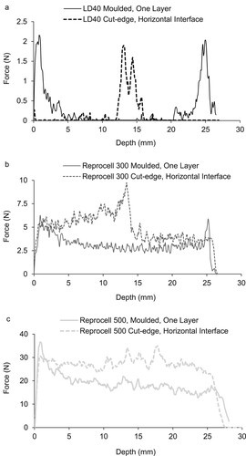
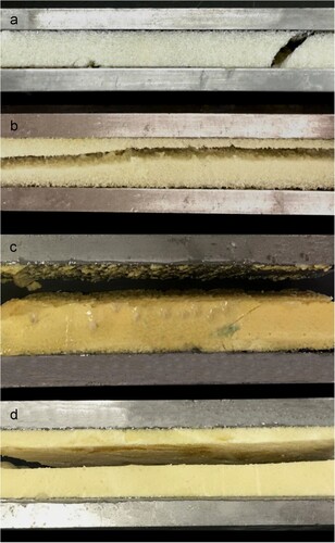
Moulded one-layer specimens exhibited a denser material at the specimen edges, where the expanding foaming material was physically constrained by the mould surface and prevented from bonding with the mould surface by the release agent. This is more pronounced with the high-expanding LD40. The effect is also clearly visible on the Reprocell 300 specimens, with the drill requiring greater force to penetrate the material at the mould boundaries of one-layered specimens. The Reprocell 500 one-layered results, however, have a significant peak at the beginning, but not at the end, showing a clearly less dense polymer matrix at the base of the specimen. illustrates a schematic diagram of material density based upon the drilling resistance results in , with the interface visible in the section of an actual specimen shown alongside.
Figure 7. Density schematic diagram and section image of a moulded, one-layered specimen (above) and cut-edged, interface specimen (below).
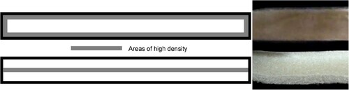
shows that as density increases there is less variation in the internal density. This is consistent with previous studies showing that if foam expansion is constrained by a boundary, cells elongate in the freely-expanding direction [Citation59], but the cellular anisotropy decreases as density increases [Citation60].
The hand-mixing of the liquid components in the laboratory is also a factor in non-homogeneity. The amount of time taken to mix the liquid components was constant, but the revolutions per minute of the manual stirring varied within that time. The liquid components were heated prior to manual mixing using a heat gun until the temperature indicated by the infrared digital thermometer reached 35
C. This introduced variation in expansion within a sample as the greater the temperature, the greater the rate of observed expansion. Additionally, although the room temperature and relative humidity were kept broadly constant, and the specimens were all created in the same space, it is entirely possible that environmental variations occurred in line with room occupancy and natural ventilation. This would affect the temperature of the mixed liquid components and, therefore, the density of the ensuing cured specimen.
Furthermore, within a confined mould, the rate of heat loss would be reduced, resulting in a higher maximum temperature being reached during the polymerisation process. Within confining boundaries, the higher temperature (in excess of 100C for Reprocell 500) promotes the exothermic reaction and, thus, expansion of the curing foam. This results in the expansion of cells away from constraining boundaries and gelation, leading to a denser polymer matrix concentrated at the moulded boundaries. The absence of a boundary is a challenge in relation to AAM, with the freshly mixed liquid foam being deposited through a nozzle onto a free surface. With no boundary (or formwork) to contain the material, the temperature of the exothermic reaction is much lower, resulting in a longer curing time.
Variance in the degree of cross-linking of the polymer chains in the foam is caused by variations of hydroxyl group numbers present in the polyol resin liquid components [Citation52]. Polyol promotes the creation of long, flexible chains and the greater the amount of excess polyol resin present, the less polyurethane chain cross-linking occurs, leading to a less stiff material and affecting the mechanical properties.
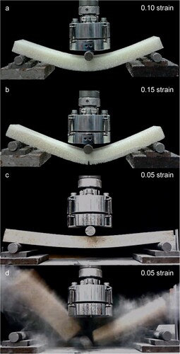
3.3. Modes of failure
illustrates the failure of LD40 and Reprocell 500 specimens during three-point bending tests where loading is parallel to interfaces. LD40 specimens (shown in (a–b)) exhibited ductile behaviour and interfaces ((b)) provided resistance to crack propagation. Reprocell 500 (shown in (c–d)) while stronger and stiffer, displayed far less ductility and brittle failure. The image in d is the immediate frame following the image in c, which emphasises the more brittle nature of the high-density foam in relation to the low-density; there is little indication of complete, sudden failure of the specimen at 0.05 strain. The Reprocell 300 specimens failed in the same manner as the Reprocell 500 specimens.
Figure 8. Flexural test specimen failure (a) LD40 one-layered. (b) LD40 with interface. (c–d) Reprocell 500 one-layered - d is the immediate frame following c, showing sudden brittle failure.
shows the failure of LD40 and Reprocell 300 specimens resulting from shear tests in which interfaces were parallel to the loading direction. LD40 one-layered specimens ((a)) showed shear failure in a diagonal plane and LD40 two-layered specimens with a horizontal interface ((b)) showed cohesive failure at the interface at a lower load, rather than a diagonal plane. Both Reprocell 300 (shown in (c)) and Reprocell 500 one-layered specimens all exhibited adhesive failure, where the specimen separated from the steel plate, whereas both Reprocell 300 (shown in (d)) and Reprocell 500 two-layered specimens with an interface, failed along that interface, again at a lower load.
Figure 9. Shear test specimen failure (a) LD40 one-layered, shear failure. (b) LD40 with a horizontal interface, cohesive failure. (c) Reprocell 300 one-layered adhesive failure. (d) Reprocell 300 with an interface, cohesive failure.
The recorded shear strength of the foams is shown in ; the shear strengths of the Reprocell foams as stated in the manufacturers' specifications [Citation54] shown in , was not verified during the tests due to adhesive failure of the one-layered specimens at a considerably lower load.
Figure 10. Shear strengths achieved for cut-edged interface specimens (cohesive failure for all three foams) and one-layered moulded specimens (adhesive failure for the Reprocell foams). Only one-layered LD40 specimens exhibited shear failure. Error bars denote the standard deviation.
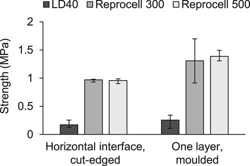
Table 2. Expected [Citation54, Citation61] and actual shear strengths achieved before shear or adhesive failure of one-layered specimens.
The results of this study suggest that there is a greater intensity of hardening agent present in the cured Reprocell specimens, improving mechanical strength, and less in the high expanding LD40 foam. The lesser cross-linked LD40 is clearly more susceptible to variations in polyol content and possesses properties quite distinct from the more cross-linked Reprocell foams. The LD40 interface specimen ((b)) shows that the relatively dense polymer matrix at the base of the second layer provided resistance to flexural failure. The Reprocell foams also possessed relatively dense polymer matrices at second layer bases (), and while the interface was not an area of weakness, it offered no discernible extra flexural strength for the Reprocell foams.
In the shear tests, interfaces were parallel to the direction of loading and were regions of weakness for all three foams. LD40 one-layered specimens failed in shear, and LD40 specimens with interfaces failed along the interface. While it was not possible to test the Reprocell 300 and 500 one-layered specimens to their full shear capacity, it can be determined that specimens with interfaces fail along the interface at a lower load than the failure load of the one-layered specimens when separating from the adhesive (). Clearly, structural design using polyurethane foam would require consideration of shear failure resulting from parallel loading as a primary design criterion.
3.4. Scanning electron microscopy
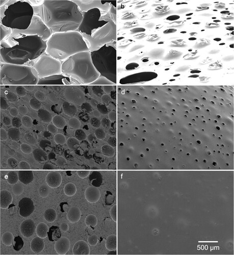
Scanning Electron Microscope images at X22 magnification () revealed that low-density LD40 foam consisted of polyhedral cells connected by thin membranes of material with triangular struts at cell vertices ((a)). By comparison, higher density Reprocell foam ((c,e)) consisted of spherical, or elongated spherical, cells with various extents of isolation within a polymer matrix. There is moderate cell anisotropy evident with the Reprocell 300 interior image ((c)) and the Reprocell 500 interior image ((e)). Both foams displayed elongation in the direction of expansion following deposition. The exterior images ((b,d,f) show dense polymer matrices and reduced visibility of cells.
Figure 11. SEM images of the polyurethane foam at X22 magnification (a) LD40, interior. (b) LD40, exterior. (c) Reprocell 300, interior. (d) Reprocell 300, exterior. (e) Reprocell 500, interior. (f) Reprocell 500, exterior.
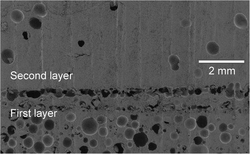
shows a Reprocell 500 interface with a very dense polymer matrix, with fewer cells in the bottom of the second layer. This contrasts sharply with the top of the first layer.
Figure 12. SEM X10 image of a Reprocell 500 specimen interface.
Polyurethane foam is not a homogeneous material and the density within each test specimen exhibits variation ( and ), with the density influenced by cell growth interacting with the boundary conditions of the mould walls and previously deposited cured foam. During the foam reactions, cells nucleate as pores (bubbles) which expand due to CO diffusion [Citation60] and the amount of gas released during the blow reaction controls material density [Citation62]. The variable, non-homogeneous nature of polyurethane foam is confirmed by the drilling resistance tests, as all results display variation of force during drilling.
Regarding the interface specimens, shows visual evidence of a dense matrix at the base of a Reprocell 500 second layer in comparison to the upper material of a first layer. The top surface of the hardened deposited first layer of material behaves as a boundary to the incoming mixed liquid of the second layer. Therefore, in drilling tests, it was the base of the second, latterly deposited layer which provided greater resistance rather than the upper surface of the first layer.
The mixed liquid of the second layer gathers at the first layer's upper surface, forming an interface. The blow reaction then causes CO filled pores to expand freely upwards and outwards. This leaves a denser polymer matrix in contact with the surface of the lower layer, which acts as a boundary, and causes expanding cells to elongate in the direction of expansion away from the boundary. Layers deposited first in an interface specimen were not subjected to an upper boundary and could freely expand vertically. Likewise, the second layer deposited allowed free vertical expansion away from the boundary of the cured first layer, and accordingly, the material did not display greater density at the cut-edged upper face.
3.5. Autonomous deposition of fresh material and representative trajectories error with end effector
The experimental aerial robotic platform with a flying base actuated by a coaxial tricopter UAV and a parallel robot can be seen grounded in (a). (b,c) depict the extrusion of low-density, high expansion polyurethane foam material in a planned circular trajectory as a proof-of-concept for AAM deposition (image b is a still taken from an AAM project video sequence [Citation50]). In a separate experiment, (d) shows layers of fresh high-density, low expansion polyurethane foam being deposited in immediate succession autonomously by the robotic arm in an arc-shaped trajectory, with subsequent layers deposited on top of uncured foam at two (d), four (d
), six (d
) and eight (d
) layers. (e) illustrates low-density, high expansion foam being trialled by hand prior to deposition using the aerial platform to test printing multiple layers in a circular trajectory, the height of an individual layer, to test multiple layers with variation in height due to expansion could be printed and to verify that there weren't any effects upon freshly extruded material due to propeller downwash (tested here using a fan). Inherent variation in layer height as the result of sprayed foam expansion is also shown. Material was sprayed at a distance of 150 mm from the printing surface at a speed of 0.0395 m/s and the mean height of a printed layer was 46 mm. A distance of 4.74 m could be sprayed over a period of 120 seconds before the nozzle clogged with curing material to the extent where printing was compromised.
Figure 13. Autonomous deposition of freshly mixed, uncured foam material. (a) Grounded UAV suitable for Aerial-AM deposition. (b) The experimental platform: flying base and parallel UAV depositing a bead of low-density foam material in a circular trajectory showing Aerial-AM in action. (Adapted from an AAM project video sequence [Citation50]). (c) A low-density foam extrusion 1 m tall. (d) Dobot magician robot arm depositing high-density foam in a programmed arc trajectory, shown at two (d), four (d
), six (d
) and eight (d
) layers. (Full details of the deposition device used are contained in [Citation48]). e) Test print of the spray low-density foam in a circular trajectory of 1.5 m diameter with three layers and application of a fan to assess any effects of downwash (left) and two layers printed showing variation in layer height (right).
![Figure 13. Autonomous deposition of freshly mixed, uncured foam material. (a) Grounded UAV suitable for Aerial-AM deposition. (b) The experimental platform: flying base and parallel UAV depositing a bead of low-density foam material in a circular trajectory showing Aerial-AM in action. (Adapted from an AAM project video sequence [Citation50]). (c) A low-density foam extrusion 1 m tall. (d) Dobot magician robot arm depositing high-density foam in a programmed arc trajectory, shown at two (d1), four (d2), six (d3) and eight (d4) layers. (Full details of the deposition device used are contained in [Citation48]). e) Test print of the spray low-density foam in a circular trajectory of 1.5 m diameter with three layers and application of a fan to assess any effects of downwash (left) and two layers printed showing variation in layer height (right).](/cms/asset/95423ba7-7019-4be1-b882-1ec576158503/nvpp_a_2305213_f0013_oc.jpg)
The aerial system was recorded in the motion capture lab (Vicon) by adding reflective markers to the printing head (tooltip), this version of the system was the structurally improved version of [Citation63]. The trajectory tracking error decreases since the aerial system has a stabilisation mechanism underneath the aerial robot. In the first case with the fixed aerial manipulator scenario, the behaviour of the aerial robot is responding with a delay and consequently underperforming the tracking. This consequently leads to deficiencies and imperfections in the printing results. In addition to the settling of the printed layers and potential sagging, those delays can cause printing interruptions, which are impossible to recompense. Other than that, it can create longer gaps in printed material than intended which will cause sagging in subsequently deposited layers. Furthermore, the delay in the reaction might lead to changes in the thickness of the printed material filament along the path, which is another problem that creates structural weaknesses.
However, the proposed mechanism demonstrated in this study takes the set points and minimises the errors occurring because of the oscillations during the aerial flight [Citation64]. By utilising precise measurements of the drone's actual position and orientation, as well as the exact geometry of the parallel robot added to the drone, the stabilisation mechanism ensures accurate alignment. This is achieved through the generation of two parallel trajectories, which consist of velocity and position set-points for both the drone body and the parallel robot arm's tooltip. These trajectories are referenced to a fixed world frame. The system then integrates the drone's measured state with the tooltip setpoint and the known geometrical parameters. This integration is crucial to determine the desired position and orientation of the tooltip in relation to its mounting point on the drone, thus ensuring stability and precision in operations where the drone and the robotic tooltip are required to function in tandem yet independently.
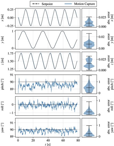
The system was further tested by intentionally disturbing the flying base in random directions and velocities. This set of random trajectories was treated as a disturbance by the end effector, and the stabilisation performance of the system was tested. The end effector keeps the error range within 10 mm range (mean) during the base oscillations that confirm the applicability of the aerial printing operation for unexpected cases, including wind gust, ground effect, unbalanced centre of gravity and additional aerodynamic interactions. Therefore, the improved stabilisation of the flight path by the system has been demonstrated. This platform with the stabilisation mechanism will be directly used in our future printing tests by considering Lidar-based onboard localisation. In the current stage, we are mimicking the trajectories and behaviour of the aerial system for our experiments, and we are aiming to integrate the aerial system with the proposed material and deposition strategy. Selected tracking performance for the tracking of tooltip trajectories is illustrated in .
Figure 14. Plots of the end-effector trajectory tracking performance of the system during a lemniscate trajectory. The violin plots show the absolute error distribution in each case. The means and the maximum and minimum extrema are shown as horizontal bars.
As shown in , freshly mixed liquid foam is deposited through a nozzle onto a free surface or a previously deposited layer (the material of which may not be cured). With no boundary (or formwork) to confine and contain the material, fluid laterally deforms, and the temperature of the exothermic reaction is lower, resulting in a longer curing time. The issue of lateral deformation is highlighted as the deposition progresses through the ten layers, with the deformation of fresh material and layer run-off while in a liquid state, rather than expansion during curing, being the primary deposition challenge. For successful AAM deposition using fresh polyurethane foam, there are several possible avenues of investigation to address the challenges of lateral deformation and prolonged curing time.
Firstly, micro-particles or nano-particles may be inserted into the freshly mixed liquid to modify the rheological properties, enhancing viscosity in order to minimise lateral deformation following extrusion without compromising the ability of the material to flow while still in the tubing of the deposition device. A second option would be an investigation into the addition of a chemical catalytic agent to increase the temperature in the mixed liquid and accelerate the exothermic reaction, leading to earlier solidification.
A third approach would be to use 3D-printed supporting material capable of receiving and containing the mixed liquid, acting as temporary confining formwork to shape the foaming liquid into the desired cured lateral dimensions, with the removal of the supporting material following full curing of the 3D-printed element. The difference in temperature recorded for the contained and free exothermic reactions (the free exothermic reaction temperature is approximately half of the contained reaction for Reprocell 500), emphasises the potential value of previously 3D-printed supporting material reducing the rate of heat loss and accelerating the exothermic foaming reaction. Temporary 3D-printed supporting material is a critical asset in AM [Citation36]. This approach may be the most viable as it would not require any modification of the polyurethane liquid, and the temporary formwork may be shaped or manipulated to realise a smooth-edged element and possibly bespoke architectural design.
3.6. Application to additive manufacturing in construction and design
Considering potential AAM construction, a possible extrusion-printed polyurethane foam cavity wall could consist of two high-density Reprocell 500 external structural skins containing internal low-density LD40 insulating layers. The Reprocell 500 foam could be printed first to the full wall height, with the ensuing LD40 layers then extruded and expanding to fill the void. Therefore, the Reprocell 500 cured foam would effectively act as containing formwork for the internal LD40 foam material, which would be most dense at the interfaces with the confining Reprocell 500 material. It is proposed that in a sequential process, potentially a team of coordinated UAVs could print with precision along programmed trajectories using high-density foam, followed in succession by a UAV spraying low-density foam between the now cured high-density extrusions.
Without moulds or formwork providing a constraining boundary, Reprocell 500 edge material would not be expected to be denser. However, if a temporary supporting 3D-printed material approach were to be used for a potential AAM foam printing application, the Reprocell 500 material would consist of a denser polymer matrix when encountering this boundary. Based upon results shown in this study, While interfaces perpendicular to loading will be an asset in LD40 3D-printed material, it can be reasoned that the horizontal interfaces between layers in 3D-printed Reprocell foam will not provide significantly higher resistance to perpendicular loading; although equally, the interface would not be an inherent weakness. However, as results demonstrate, where loading is parallel to an interface, a material interface would indeed be a region of weakness in the structure for all foams.
It is recommended that the architectural and structural design considerations of a potential 3D-printed building using polyurethane foam would be informed by the desire to minimise interfaces in the material parallel to structural loading. Domes and gridshells are potential design solutions for AAM structures. With domes, it is plausible to use supporting inflatable objects on which to 3D-print polyurethane foam and subsequently deflate once curing has taken place. A potential grid-shell approach would involve the prior erection of a mesh framework on which to print, which could remain as a permanent reinforcing element within 3D-printed polyurethane foam material, in combination with temporary 3D-printed supporting material being applied to externally confine the extruded foam. These potential options would support interfaces vulnerable to parallel loading, which has been shown by this study to be an important consideration.
The aerial approach to AM offers enormous scope for repairing structures in addition to assessing them, particularly with the ability of the airborne deposition device to extrude material at height and the ability of the material to expand and fill cracks and voids [Citation65]. It is postulated that an aerial approach would have a major impact on reducing all labour-associated costs, risks and time delays, most significantly the safety risk of people having to work at height, with the potential for aerial robots to autonomously perform tasks currently requiring dangerous scaffolding erection or abseiling. Logistical considerations concerning the vertical transport of materials from ground-based vehicles would additionally be mitigated.
It is further suggested that AAM would potentially transform construction on challenging or uneven terrain, where the use of heavy ground-based methods and machinery is inherently problematic, a particular example applicable on a global scale being post-earthquake disaster reconstruction. Additionally, AAM offers scope for bespoke design as AM processes are liberated from the ground and on a construction-scale project, the opportunity to reduce material wastage by only printing material specifically required for the project would be significant.
4. Conclusions
The study has investigated the behaviour of both high and low-density polyurethane foam for Aerial Additive Manufacturing (AAM) and has demonstrated the autonomous deposition of polyurethane foam in planned trajectories using flying untethered unmanned aerial vehicles (UAV) and a robotic arm. AAM using foam would combine high-density structural foam skins with low-density internal insulating foam and could use 3D-printed temporary supporting material to contain freshly extruded liquid, accelerating the exothermic foaming reaction and promoting high-density cured foam matrices.
Rigid polyurethane foam possesses greater density at interfacial and imposed boundary regions, where mixed liquid components have encountered cured and/or solid matter whilst foaming. This inhomogeneity is more pronounced in low-density, high-expanding foam and becomes less pronounced as foam density and polymer chain cross-linking increase and anisotropic cell expansion decreases. Although rigid polyurethane foam possesses greater density at interfacial regions, an asset when loaded perpendicularly, interfaces are vulnerable to parallel loading and consideration of this should inform architectural and structural design. Improved flight stabilisation for an AAM platform has been demonstrated as the end effector keeps the printing trajectory error range within 10 mm during the base oscillations, showing the application of the aerial printing operation compensating for unexpected UAV flight disturbance scenarios including sudden gusts of wind, uneven ground effects and unbalanced centre of UAV gravity resulting from aerodynamic interactions. When considering multiple layers in a printing application, improved flight stabilisation allows for more precise deposition, thus maximising the adhesion between layers.
The significance of this study in AAM is the development and demonstration of an untethered aerial high-precision foam-extruding application which can promote on-site automation in construction. The use of foam for AAM would be particularly suited to construction in harsh, challenging environments or elevated applications, reducing the requirement for inherently dangerous work at height.
Geo-location
The authors of this paper are based primarily in the United Kingdom, with affiliations in London, Bath and Bristol. Selected authors have an additional affiliation based in Dubendorf, near Zurich, Switzerland.
Author contribution
Barrie Dams: Writing − Original Draft, Writing -- Review & Editing, Conceptualisation, Methodology, Validation, Investigation, Formal Analysis, Visualisation. Lachlan Orr: Writing − Original Draft, Investigation, Formal Analysis, Visualisation. Yusuf Furkan Kaya: Writing − Original Draft, Investigation, Formal Analysis, Visualisation. Bahadir Basaran Kocer: Writing − Original Draft, Investigation, Formal Analysis, Visualisation. Paul Shepherd: Conceptualisation, Writing − Review & Editing, Supervision, Methodology. Mirko Kovac: Conceptualisation, Writing − Review & Editing, Supervision, Funding Acquisition, Project Administration, Methodology. Richard Ball: Conceptualisation, Writing − Review & Editing, Supervision, Funding Acquisition, Project Administration, Methodology.
Acknowledgments
The authors express thanks to the following: Dr Ketao Zhang (Automated deposition device development, Imperial College London, UK and Queen Mary University, London, UK). Dr Sina Sareh (Automated deposition device development, Imperial College London, UK and Royal College of Art, London, UK). Shamsiah Awang-Ngah and Sheldon Wang for adhesion and mechanical removal of samples support (University of Strathclyde and University of Bath, UK). Members of the Aerial Robotics Laboratory at Imperial College, London, UK and the Laboratory of Sustainability Robotics at Empa, Switzerland. The technical support of the Department of Architecture and Civil Engineering laboratories and the Microscopy analysis suite, MC, University of Bath, UK.
Data availability statement
The data that support the findings of this study are openly available in the ‘University of Bath data archive’ at https://doi.org/10.15125/BATH-00385, reference number [00385].
Disclosure statement
The authors report there are no competing interests to declare.The authors declare that they have no financial interests or personal relationships that could have appeared to influence the work reported in this paper. The authors confirm approval of the finished manuscript and consent to co-authorship. All listed authors contributed to the final manuscript, which is wholly original and is not under consideration by an alternative publication.
Additional information
Funding
References
- Ashrafi N, Duarte JP, Nazarian S, et al. Evaluating the relationship between deposition and layer quality in large-scale additive manufacturing of concrete. Virtual Phys Prototyp. 2019;14:135–140. doi: 10.1080/17452759.2018.1532800.
- Lim S, Buswell RA, Le TT, et al. Developments in construction-scale additive manufacturing processes. Automation in Construction. 2012;21:262–268. doi: 10.1016/j.autcon.2011.06.010
- Ames J, White DJ, Alhasan A. Conference on Autonomous and Robotic Construction of Infrastructure Proceedings of the 2015 Conference on Autonomous and Robotic Construction of Infrastructure, Proceedings of the 2015 Conference on Autonomous and Robotic Construction of Infrastructure (2015).
- Raza MH, Zhong RY, Khan M. Recent advances and productivity analysis of 3D printed geopolymers. Addit Manuf. 2022;52:102685.
- Bos F, Wolfs R, Ahmed Z, et al. Additive manufacturing of concrete in construction: potentials and challenges of 3D concrete printing. Virtual Phys Prototyp. 2016;11:209–225. doi: 10.1080/17452759.2016.1209867.
- Vaezi M, Chianrabutra S, Mellor B, et al. Multiple material additive manufacturing–part 1: a review: this review paper covers a decade of research on multiple material additive manufacturing technologies which can produce complex geometry parts with different materials. Virtual Phys Prototyp. 2013;8:19–50. doi: 10.1080/17452759.2013.778175.
- Ahmed ZY, Bos FP, Van Brunschot M, et al. On-demand additive manufacturing of functionally graded concrete. Virtual Phys Prototyp. 2020;15:194–210. doi: 10.1080/17452759.2019.1709009.
- Wang M, Wang CC, Sepasgozar S, et al. A systematic review of digital technology adoption in off-site construction: current status and future direction towards industry 4.0. Buildings. 2020;10:204. doi: 10.3390/buildings10110204.
- WASP. The infinite 3D printer 3D WASP 2022, 2022. Available from: https://www.3dwasp.com/en/3d-printer-house-crane-wasp/.
- ICON. ICON and lennar to build largest neighborhood of 3D-printed homes codesigned by BIG-Bjarke Ingels Group, 2022. Available from: https://www.iconbuild.com/updates/icon-and-lennar-to-build–largest-neighborhood-of-3d-printed-homes-codesigned.
- Winsun. 3D printing architecture's future, 2022. Available from: http://www.winsun3d.com/En/Index/.
- Apis Cor. A revolutionary robotic 3D printer, 2022. https://apis-cor.com/.
- Tiryaki ME, Zhang X, Pham Q-C. Printing-while-moving: a new paradigm for large-scale robotic 3D printing. In: 2019 IEEE/RSJ International Conference on Intelligent Robots and Systems (IROS). IEEE; 2019. p. 2286–2291.
- Krizmancic M, Arbanas B, Petrovic T, et al. Cooperative aerial-ground multi-robot system for automated construction tasks. IEEE Robot Autom Lett. 2020;5:798–805. doi: 10.1109/LSP.2016..
- Alhijaily A, Kilic ZM, Bartolo AP. Teams of robots in additive manufacturing: a review. Virtual Phys Prototyp. 2023;18:e2162929. doi: 10.1080/17452759.2022.2162929.
- Giftthaler M, Sandy T, Dörfler K, et al. Mobile robotic fabrication at 1: 1 scale: the in situ fabricator: system, experiences and current developments. Constr Robot. 2017;1:3–14. doi: 10.1007/s41693-017-0003-5.
- Dakhli Z, Lafhaj Z. Robotic mechanical design for brick-laying automation. Cogent Eng. 2017;4:1361600. doi: 10.1080/23311916.2017.1361600.
- Helm V, Ercan S, Gramazio F, et al. Mobile robotic fabrication on construction sites: dimrob. In: 2012 IEEE/RSJ International Conference on Intelligent Robots and Systems. IEEE; 2012. p. 4335–4341.
- Yablonina M, Prado M, Baharlou E, et al. Mobile robotic fabrication system for filament structures. Fabricate Rethinking Des Constr. 2017;3:202–209.
- Wang L, Culha U, Iida F. A dragline-forming mobile robot inspired by spiders. Bioinspir Biomim. 2014;9:016006. doi: 10.1088/1748-3182/9/1/016006.
- Braithwaite A, Alhinai T, Haas-Heger M, et al. Tensile web construction and perching with nano aerial vehicles. Robot Res Vol. 2018;1:71–88. doi: 10.1007/978-3-319-51532-8.
- Zhang X, Li M, Lim JH, et al. Large-scale 3D printing by a team of mobile robots. Autom Constr. 2018;95:98–106. doi: 10.1016/j.autcon.2018.08.004.
- Sustarevas J, Butters D, Hammid M, et al. Map-a mobile agile printer robot for on-site construction. In: 2018 IEEE/RSJ International Conference on Intelligent Robots and Systems (IROS). IEEE; 2018. p. 2441–2448.
- Oxman N, Duro-Royo J, Keating S, et al. Towards robotic swarm printing. Archit Des. 2014;84:108–115.
- Jokic S, Novikov P, Maggs S, et al. Robotic positioning device for three-dimensional printing, arXiv preprint arXiv:1406.3400. 2014.
- Petersen KH, Napp N, Stuart-Smith R, et al. A review of collective robotic construction. Sci Robot. 2019;4:eaau8479. doi: 10.1126/scirobotics.aau8479.
- Hauf F, Kocer BB, Slatter A, et al. Learning tethered perching for aerial robots. In: 2023 IEEE International Conference on Robotics and Automation (ICRA). IEEE; 2023. p. 1298–1304.
- Dillow C. Drones take off in the construction industry as a cost-saving tool — Fortune.com, 2016. Available from: http://fortune.com/2016/09/13/commercial-drone-construction-industry/.
- Drones Direct. The UK drone users report, 2017. Available from: http://www.dronesdirect.co.uk/files/pdf/dronesreport.pdf.
- Feron E, Johnson EN. Aerial robotics. In: Springer handbook of robotics F/44. Berlin (Germany): Springer Science & Business Media; 2008. p. 1009–1029. Available from: http://link.springer.com/content/pdf/10.1007/978-3-540-30301-5_45.pdf\%5Cnpapers3://publication/uuid/FCD0AE08-B03E-4D9D-AD43-3D5385728D72.
- Health and Safety Executive. Fatal injuries arising from accidents at work in Great Britain 2017. 2017. p. 1–16.
- Nadhim EA, Hon C, Xia B, et al. Falls from height in the construction industry: a critical review of the scientific literature. Int J Environ Res Public Health. 2016;13. doi: 10.3390/ijerph13070638
- Occupational Safety and Health Administration. Commonly Used Statistics — Occupational Safety and Health Administration, 2015. Available from: https://www.osha.gov/oshstats/commonstats.html.
- Zhang L, Ding X, Ou Y. Properties of rigid polyurethane foams prepared with synthesized PIPA polyol. Am J Appl Chem. 2014;1:7–14. Available from: http://www.aascit.org/journal/ajca
- Widya T, Macosko C. Nanoclay modified rigid polyurethane foam. J Macromol Sci Part B Phys. 2005;44:897–908. doi: 10.1080/00222340500364809
- Barnett E, Gosselin C. Weak support material techniques for alternative additive manufacturing materials. Addit Manuf. 2015;8:95–104. doi: 10.1016/j.addma.2015.06.002
- Barnett E, Gosselin C. Large-scale 3D printing with a cable-suspended robot. Addit Manuf. 2015;7:27–44.
- Furet B, Poullain P, Garnier S. 3D printing for construction based on a complex wall of polymer-foam and concrete. Addit Manuf. 2019;28:58–64.
- Bedarf P, Dutto A, Zanini M, et al. Foam 3D printing for construction: a review of applications, materials, and processes. Autom Constr. 2021;130:103861. doi: 10.1016/j.autcon.2021.103861.
- Keating SJ, Leland JC, Cai L, et al. Toward site-specific and self-sufficient robotic fabrication on architectural scales. Sci Robot. 2017;2:eaam8986. doi: 10.1126/scirobotics.aam8986.
- Prajapati MJ, Kumar A, Lin S-C, et al. Multi-material additive manufacturing with lightweight closed-cell foam-filled lattice structures for enhanced mechanical and functional properties. Addit Manuf. 2022;54:102766.
- Labonnote N, Ronnquist A, Manum B, et al. Additive construction: state-of-the-art, challenges and opportunities. Autom Constr. 2016;72:347–366. doi: 10.1016/j.autcon.2016.08.026
- Frearson A. DUS Architects builds 3D-printed micro home in Amsterdam, 2016. Available from: https://www.dezeen.com/2016/08/30/dus-architects-3d-printed-micro-home-amsterdam-cabin-bathtub/.
- Hunt G, Mitzalis F, Alhinai T, et al. 3D printing with flying robots. In: 2014 IEEE International Conference on Robotics and Automation (ICRA). IEEE; 2014. p. 4493–4499.
- Chermprayong P, Zhang K, Xiao F, et al. An integrated delta manipulator for aerial repair: a new aerial robotic system. IEEE Robot Autom Mag. 2019;26:54–66. doi: 10.1109/MRA.100.
- Chermprayong P. Enabling technologies for precise aerial manufacturing with unmanned aerial vehicles. 2019.
- Alhinai TMT. Methods of manufacturing with aerial robots [Ph.D. thesis]. Imperial College London; 2019.
- Dams B, Sareh S, Zhang K, et al. Aerial additive building manufacturing: three-dimensional printing of polymer structures using drones. Proc Inst Civil Eng-Constr Mater. 2020;173:3–14.
- Dams B. Cementitious and polymeric materials for aerial additive manufacturing [Ph.D. thesis]. University of Bath; 2020.
- Zhang K, Chermprayong P, Xiao F, et al. Aerial additive manufacturing with multiple autonomous robots. Nature. 2022;609:709–717. doi: 10.1038/s41586-022-04988-4.
- Alaa M, Yusoh K, Hasany S. Pure polyurethane and castor oil based polyurethane: synthesis and characterization. J Mech Eng Sci (JMES). 2015;8:1507–1515. doi: 10.1002/mrm.10658
- Trovati G, Sanches EA, Neto SC, et al. Characterization of polyurethane resins by FTIR, TGA, and XRD. J Appl Polym Sci. 2010. doi: 10.1002/app.31096
- Zhao Y, Gordon MJ, Tekeei A, et al. Modeling reaction kinetics of rigid polyurethane foaming process. J Appl Polym Sci. 2013;130:1131–1138. doi: 10.1002/app.39287
- Isothane Ltd.. LD40 -- Isothane, 2016. http://www.isothane.com/prod/ld40/.
- Ridha M, Shim VPW. Microstructure and tensile mechanical properties of anisotropic rigid polyurethane foam. Exp Mech. 2008;48:763–776. doi: 10.1007/s11340-008-9146-0
- BSI. BS ISO 1922 : 2012 BSI Standards Publication Rigid cellular plastics – Determination of shear strength. 2012.
- BSI. Rigid cellular materials – Part 4: method 14. Determination of flexural properties, BS 4370-4:1991 (2008).
- PX4. PX4 user guide. Available from: https://docs.px4.io/main/en/, [???? accessed: 2022 May 02].
- Mills N. Chapter 2 Polyurethane foams: processing and microstructure. In: Polymer foams handbook. Oxford (UK): Elsevier Ltd.; 2007. doi: 10.1016/B978-0-7506-8069-1.50003-9
- Dawson JR, Shortall JB. The microstructure of rigid polyurethane foams. J Mater Sci. 1982;17:220–224. doi: 10.1007/BF00809056
- Isothane Ltd.. The reprocell range -- isothane, 2016. Available from: http://www.isothane.com/prod/reprocell-range/.
- Saint-Michel F, Chazeau L, Cavaillé J-Y. Mechanical properties of high density polyurethane foams: II effect of the filler size. Compos Sci Technol. 2006;66:2709–2718. doi: 10.1016/j.compscitech.2006.03.008
- Orr L, Stephens B, Kocer BB, et al. A high payload aerial platform for infrastructure repair and manufacturing. In: 2021 Aerial Robotic Systems Physically Interacting with the Environment (AIRPHARO). IEEE; 2021. p. 1–6.
- Stephens B, Orr L, Kocer BB, et al. An aerial parallel manipulator with shared compliance. IEEE Robot Autom Lett. 2022;7:11902–11909. doi: 10.1109/LRA.2022.3205111.
- Kocer BB, Orr L, Stephens B, et al. An intelligent aerial manipulator for wind turbine inspection and repair. In: 2022 UKACC 13th International Conference on Control (CONTROL). IEEE; 2022. p. 226–227.