
 ?Mathematical formulae have been encoded as MathML and are displayed in this HTML version using MathJax in order to improve their display. Uncheck the box to turn MathJax off. This feature requires Javascript. Click on a formula to zoom.
ABSTRACT
This study investigates the mechanical behavior of a novel set of Cuboidal Spherical Plate Lattice (CSPL) materials. The procedure of constrained-domain topology optimization is implemented with the aim of enhancing stiffness. The micromechanical finite element homogenization approach is used to evaluate the effective elastic-plastic properties of the CSPLs and their topologically optimized counterparts, TOCSPLs (Topologically Optimized Cuboidal Spherical Plate Lattices). The TOCSPLs demonstrate higher uniaxial, shear, and bulk moduli compared to the CSPLs, with an increase of 31%, 14%, and 36% respectively. Moreover, there is an increase in the yield strengths under uniaxial, shear, and hydrostatic loading conditions, with enhancements of 103%, 55%, and 62%, respectively. The topologies are additively manufactured through Fused Deposition Modeling (FDM) out of ABS thermoplastic material. The quasi-static compression experiments demonstrate the superiority of TOCSPL 111+100 over the other topologies in terms of uniaxial modulus. The suffix 111+100 denotes the crystallographic planar orientations in which the solid plate-like disks were formed within a cubic system. The topologies proposed herein outperform certain types of Triply Periodic Minimal Surface, honeycomb, truss-, and plate-based lattice materials. The proposed topologies offer a compelling justification for their utilization in applications that require load-bearing and impact absorption capabilities.
1. Introduction
The technological advancement in additive manufacturing, also known as 3D printing, enabled the production of intricate geometries consisting of interconnected networks of struts, beams, and plates, known as lattice materials or structures, that could not be produced by conventional manufacturing techniques. Lattice materials, also known as metamaterials or architected cellular materials, gained interest due to their multifunctionality and unique physical and mechanical properties, such as, exhibiting electromagnetic cloaking (i.e. making an object invisible in a specific frequency range) [Citation1], negative stiffness [Citation2] and Poisson’s ratio [Citation3]. Several types of lattice materials were developed throughout the past decades, e.g. truss-based lattice materials consisting of a network of struts connected at nodes [Citation4], while Triply Periodic Minimal Surfaces (TPMSs) comprising of non-intersecting and smooth surfaces such that the mean curvature at each point on the surface is zero [Citation5], and plate-based lattices, which are closed-cell lattices consisting of solid plates commonly extruded in the closed-packed planes of a cubic crystal system [Citation6].
The performance of a lattice structure is significantly impacted by its topology, base material, and relative density (). Relative density (
) is calculated as the ratio of the density of the lattice material (
) to the density of the solid base material (
), expressed as
. Multiple studies have examined how the latter characteristics affect the mechanical properties of lattice materials. For example, Bahgous et al. [Citation7,Citation8] studied the yield surface of several types of TPMSs at different relative densities. Ahmed et al. [Citation9,Citation10] examined the effect of residual stresses on the mechanical properties of additively manufactured lattice materials. In terms of the topology-mechanical property relationship, Altamimi et al. [Citation11] demonstrated that for the same base material and relative density, thirty types of strut-based lattice materials exhibited unique mechanical properties. Viswanath et al. [Citation12] highlighted the influence on the mechanical behaviour of sheet-based Schoen’s Gyroid TPMS structure when converted into a strut-based structure, as the strut-based designs demonstrated greater fatigue resistance at the cost of elastic modulus. Although the truss-based lattice structures have been thoroughly investigated in the literature, the stress concentrations at the junction of struts deteriorate their stiffness [Citation13]. To address this challenge, Alomar and Concli [Citation14] suggested a lattice structure design based on circular cells. This design possessed a smooth topology and ensured an even distribution of stress. Alternatively, plate-based lattice structures were proved to be three times stiffer than the stiffest truss-based lattice structure for the same relative density [Citation15]. Berger et al. [Citation6] demonstrated the capability of plate-based lattice structures in attaining the theoretical limit of isotropic elastic stiffness.
A more recent approach investigating the topology-mechanical property relationship involves the implementation of topology optimisation procedure to improve the material distribution in a given design for maximizing/minimizing an objective function (e.g. stiffness maximisation, stress minimisation, or mass minimisation). On the basis of mathematical formulation, topology optimisation utilises finite element method to optimise the material distribution within a design domain, for a given set of constraints, loads, and boundary conditions [Citation16,Citation17]. With the aim of improving the stiffness-to-weight ratio and hence enhancing the load-bearing capability of a structure, stiffness maximisation (i.e. compliance minimisation) of lattice materials has been receiving a growing interest. Xiao et al. [Citation18] optimised the stiffness of a solid cube, subject to several volume constraints and compressive loading cases, resulting in beam-based topologies. Duan et al. [Citation19] synthesised designs very similar to the Schwarz Primitive TPMS with maximal shear and bulk moduli. Both studies produced designs with comparable stiffness and strength to that of truss-based lattice materials. Zeng et al. [Citation20] adopted inverse design procedure to produce topologically optimised metamaterials for impact absorption application. Recently, Alawwa et al. [Citation21] proposed a number of innovative lattice materials derived by free-domain and constrained domain topology optimisation procedures. The optimised lattice structures they employ comprise beams and struts, which are suboptimal geometries for applications demanding load-bearing and deformation resistance. It is imperative to employ more efficacious shapes, notably plate-based structures, to fully harness the potential of topology optimisation in crafting lattice structures that exhibit superior stiffness and strength. This consideration underscores the focus of the present study, which proposes a novel set of lattice materials called Cuboidal Spherical Plate Lattice (CSPL). The foundation of the CSPL structures lies in plate-based lattices, renowned for their exceptional stiffness and strength relative to other lattice configurations. In this study, we augment these lattice structures by employing a constraint domain topology optimisation approach to further optimise their performance characteristics. The technique is based on preserving the original design while allowing a free-domain to evolve into novel topologically optimised features under prescribed loading and boundary conditions. The micromechanical finite element homogenisation analysis demonstrated the outperformance of the CSPLs and their topologically optimised counterparts TOCSPLs when compared to a certain group of Triply periodic Minimal Surface (TPMS) and truss-based lattice materials. A few of the proposed designs attained the theoretical elastic (i.e. Hashin-Shtrikman upper bound) and yield strength (i.e. Suquet upper bound) limits for cellular materials. For a thorough mechanical characterisation, the proposed topologies were additively manufactured by Fused Deposition Modelling (FDM) additive manufacturing technique and afterwards subjected to compression testing. The experimental outcomes revealed the superiority of the proposed designs in terms of uniaxial modulus, yield strength, and energy absorption when compared to that of several lattices from literature, including, honeycomb, TPMS, truss-, and plate-based designs.
2. Design of cuboidal spherical plate lattices (CSPLs)
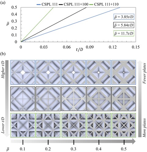
demonstrates the procedure of generating a representative volume element (RVE), i.e. a single unit cell, of the CSPLs investigated in the present study. Initially, solid plate-like disks were generated in a cubic system identified with crystallographic planer directions (i.e. [100], [110], [111]). As depicted in (a), the procedure of generating a CSPL 111 involves the production of a Spherical Plate Lattice (SPL) composing of solid disks with a diameter of D and a thickness of t, extruded in the [111] planer direction in a cubic system. Thereafter, any portion of the SPL 111 protruding from the cubic system is truncated in order to synthesise the CSPL 111 structure with cubic symmetry. Similarly, the same procedure is applied to produce the CSPL 111 + 100 ((b)) and the CSPL 111 + 110 ((c)) lattice materials. In these designs, the plate thickness (i.e. the disk thickness) of the CSPLs is varied to control their relative density for a fixed diameter (i.e. unit cell length). (a) shows the correlation between the relative density and the aspect ratio (t/D) of the CSPLs. Among the three, the CSPL 111 has the greatest aspect ratio, followed by the CSPL 111 + 100, and then the CSPL 111 + 110, when compared at the same relative density. This is expected because as the number of constituent plates in the cubic system increases, the designs with more plates become thinner and more susceptible to structural buckling, and the contrary for designs with fewer plates which become thicker and bulkier, as shown in (b).
Figure 1. The procedure of generating the CSPL unit cells, showing: (a) CSPL 111, (b) CSPL 111 + 100, and (c) CSPL 111 + 110.
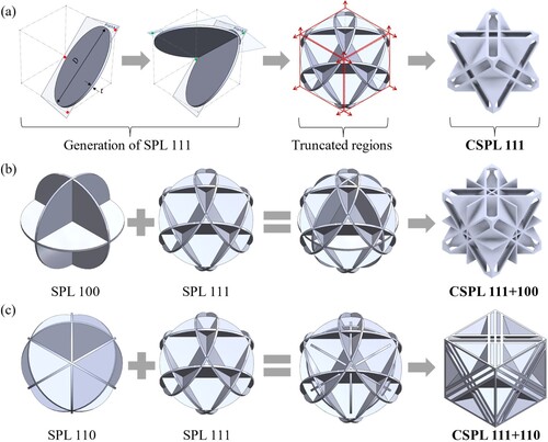
Figure 2. Demonstrating the correlation between the relative density and the aspect ratio for the CSPLs: (a) linear correlation between and t/D, and (b) illustrating cross-sections from the top view of the designs at different
and t/D.
3. Micromechanical finite element analysis
The present study adopts the micromechanical finite element homogenisation approach based on a representative volume element (RVE) to compute the effective elastic and yield properties of the CSPLs at different . The elastic properties include the uniaxial elastic
, bulk
, and shear
moduli, while the yield properties include the uniaxial (
), hydrostatic (
), and shear (
) yield strengths. Using the micromechanics plugin for Abaqus/CAE developed by Dassault Systems, periodic boundary conditions (PBC) were imposed on the RVEs to capture their effective bulk response and ensure the displacement compatibility and traction continuity across the boundaries of the adjacent unit cells [Citation7,Citation8,Citation22,Citation23].
Herein, and for the purpose of the RVE simulations, small deformation and rate-independent linear elastic-perfectly plastic isotropic material behaviour is assumed for the base material of the CSPLs. For computing the yield properties of the CSPLs, the solid base material was assumed to yield according to the classical J2 flow theory of plasticity, and assigned a Young’s modulus of = 1 GPa, Poisson’s ratio of
= 0.35, and an initial yield strength of
= 32 MPa, corresponding to a yield strain
of 0.2% [Citation24]. The CSPLs possess cubic symmetry, thereby only three independent elastic constants are required to describe their effective macroscopic elastic response, governed by the following constitutive relation:
(1)
(1) where
and
represent the average stress and the infinitesimal strain tensors components, respectively. Here
,
,
are the three independent effective elastic constants, where
,
, and
, where
, E and G are the effective Poisson’s ratio, elastic modulus and shear modulus of the CSPLs. Furthermore, the Zener index is a measure of the level of elastic anisotropy of a cubic lattice material, and is defined as
, where the value
corresponds to an isotropic material behaviour, while the values
or
indicate anisotropy such that the shear moduli of the considered lattice material is lower or greater than that of an equivalent isotropic material, respectively [Citation25]. From the output of the homogenised material response (i.e.
and
), the bulk modulus
can be calculated as follows:
(2)
(2)
3.1. Effective elastic properties of CSPLs
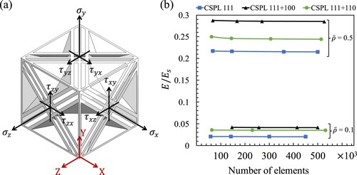
As depicted in (a), the uniaxial tension loading was applied using (i.e.
) only, while the pure shear loading consisted of applying
(i.e.
) only, and the hydrostatic tension lading was applied using
,
, and
(i.e.
,
,
) where
. Due to the cubic symmetry, we have that
and
. The RVE simulations were conducted in Abaqus/Standard using a static step with a time increment of 0.1. All simulations utilised the 10-node quadratic tetrahedron (C3D10) elements. A mesh sensitivity analysis was performed to verify that the results obtained are independent of the mesh size for all designs. (b) demonstrates the mesh sensitivity analysis conducted to estimate the effective uniaxial modulus of the CSPLs at relative densities of 0.1 and 0.5. To account for the variation in plate thickness of the CSPLs across different relative densities, it was assured that all simulations were performed using a converged mesh size.
Figure 3. (a) 3D model of CSPL 111 + 110 deomstrating the normal and the shearing stresses, and (b) mesh sensitivity analysis for the CSPLs at different relative densities.
The effective elastic properties in were compared against the theoretical upper bounds for uniaxial, shear, and bulk moduli (i.e. Hashin-Shtrikman upper bounds) [Citation26]. These bounds are given by Equations (3)–(5), where the subscripts and
represent the Hashin-Shtrikman upper bound and base material properties, respectively:
(3)
(3)
(4)
(4)
(5)
(5)
Figure 4. Normalised effective elastic properties of the CSPLs, (b) uniaxial modulus, (c) shear modulus and (d) bulk modulus.
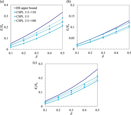
shows the effective elastic moduli normalised with respect to as a function of
fitted with the Gibson-Ashby scaling power-law [Citation27] in the form of
, where
is the property of interest (e.g. elastic modulus or strength),
is the property of the base material,
is the scaling coefficient, and
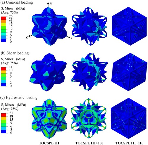
is the scaling exponent. displays the Mises stress contours for three loading conditions: uniaxial tensile, pure shear, and hydrostatic loading. These contours correspond to lattice structures with
= 0.4. It should be noted that the structures were subjected to a strain of 0.1% in order to calculate the effective elastic moduli.
The scaling power-laws summarised in are commonly utilised to investigate the deformation mode of lattice materials and classify their fitness for impact absorption (i.e. bending-dominated mode) or load-bearing (i.e. stretching-dominated mode) applications [Citation27,Citation28]. For example, the members (i.e. truss, beams, or plates) of a stretching-dominated lattice material would deform axially when subjected to external loading. This type of lattice material exhibits a scaling exponent of for stiffness and strength. On the other hand, a bending-dominated lattice material deforms by bending or buckling and exhibits a scaling exponent of
for stiffness or
for strength, while the values in between denote a mixed-mode of deformation [Citation24].
Figure 5. Mises stress distribution in CSPLs with = 0.4 for various loading conditions: (a) uniaxial, (b) shear and (b) hydrostatic loading.
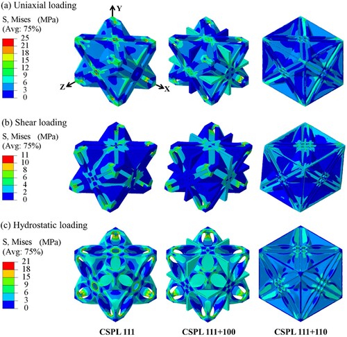
Table 1. A summary of the scaling law parameters of the elastic moduli of the CSPLs.
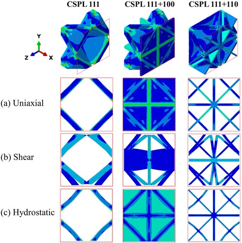
The scaling power-laws indicate that the CSPL 111 lattice exhibits a mixed-mode of deformation while the CSPL 111 + 100 and the CSPL 111 + 110 lattices demonstrate a near stretching-dominated deformation mode. The findings suggest that combining the CSPL 111 design with constituent plates oriented in the planar directions of [100] and [110] leads to a shift in the deformation mode from a mixed mode to a predominantly stretching mode. This concept is further demonstrated in (a), specifically in the scenario of uniaxial loading. In this situation, reinforcing the CSPL 111 design with three orthogonal plates helps to counteract the bending of the structure and enhances its ability to withstand the applied tensile load in the positive X-direction. Contrary to reinforcing the structure in three perpendicular directions, the CSPL 111 + 110 design provides support to the structure in two perpendicular directions (i.e. in the X and Y orientations), as well as at eight vertices of the cubic system. This design optimisation is aimed at enhancing the structure’s ability to withstand pure shear loading. Consequently, the CSPL 111 + 100 and CSPL 111 + 110 lattice structures exhibit the highest uniaxial and shear stiffness, as illustrated in (a and b), respectively. In addition, (b and c) demonstrate that combining the CSPL 111 design with constituent plates in the [110] orientation prevents the structure from collapsing under pure shear and hydrostatic loading. This result provides additional justification for the dominance of the CSPL 111 + 110 design in terms of bulk and shear moduli, as demonstrated in (b and c), respectively.
Figure 6. Demonstrating the deformation modes of the CSPLs under (a) uniaxial, (b) shear, and (c) hydrostatic loading for the case of = 0.4.
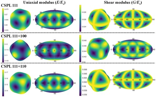
To reinforce the findings mentioned earlier, the elastic anisotropy distributions for the uniaxial and shear moduli are depicted in for a relative density of 0.4. The ellipsoid-like shape visualisations represent the Mollweide map projection [Citation29] that describe the variation of elastic properties with spatial direction. Using the three independent effective elastic constants, these visualisations were generated using the VELAS open-source toolbox written in GNU Octave [Citation30]. demonstrates that the CSPL 111 + 100 exhibits the highest level of elastic anisotropy in the ,
,
directions (i.e. [100], [010], [001] planer direction) when compared to that of the CSPL 111 and CSPL 111 + 110. This confirms the hypothesis of enhancing the load-bearing capability of the CSPL 111 design by combining it with three orthogonal plates. Furthermore, a strong spatial shear elastic anisotropy is observed in the Mollweide map projection for the CSPL 111 + 110 design, covering the range of −90°
90° and −180°
180°. This explains its capability in attaining the HS upper bound under shear loading for a range of relative density values between 0.1 and 0.3.
Figure 7. Uniaxial and shear moduli distributions of CSPLs with = 0.4.
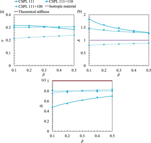
(a) demonstrates the effective Poisson’s ratio of the CSPLs computed from the previously described homogenisation approach. Likewise, the identical values could be obtained using the relation . Results reveal that the effective Poisson’s ratios of the CSPL 111 + 110 and the CSPL 111 + 100 are nearly insensitive to increasing relative density, particularly after
= 0.2. On the contrary, the CSPL 111 effective Poisson’s ratio decreases marginally with relative density. In terms of elastic anisotropy of CSPLs, (b) shows that the Zener’s index A for CSPL 111 and CSPL 111 + 110 decrease with increasing
, while A for CSPL 111 + 100 increases with increasing
. As a metric of elastic performance, Berge et al. [Citation6] quantified the capability of a lattice material in attaining the HS upper bounds by its total stiffness given by
(6)
(6)
where = 1 indicates achieving the three theoretical HS upper bounds simultaneously. (c) demonstrates that the CSPL 111 + 110 and the CSPL 111 + 100 lattices perform within 75–80% of the theoretical stiffness, while the CSPL 111 exhibits an improvement in
with increasing relative density.
Figure 8. Elastic parameters for CSPLs: (a) effective Poisson’s ratio , (b) Zener’s index A for and (c) total stiffness
.
3.2. Effective yield properties of CSPLs
The effective yield strengths of the CSPLs were calculated using the identical boundary conditions as those used for estimating the effective elastic properties. (a–c) show the effective stress–strain curves for the case of = 0.5. In these simulations, the lattice structures were loaded beyond yielding subjected to uniaxial, shear, and hydrostatic loading cases. The effective uniaxial (
), shear (
), and hydrostatic (
) yield strengths were calculated using the 0.2% strain offset method. Correspondingly, (d–f) show the effective yield strengths normalised with respect to the uniaxial yield strength of the base material (
) as a function of
fitted with Gibson-Ashby scaling power-law. The CSPL 111 + 110 demonstrates higher shear and hydrostatic strengths in comparison to other designs, which are similar to the patterns observed in the elastic simulations of the structures. summarises the scaling law parameters of the yield strengths. It can be noticed that the CSPLs exhibited a mixed-mode of deformation under the prescribed loading conditions, though the CSPL 111 exhibited a strong bending-dominated deformation mode under pure shear loading.
Figure 9. Effective stress-strain curves for (a) CSPL 111, (b) CSPL 111 + 100, (c) CSPL 111 + 110, and normalised effective yielding properties: (d) uniaxial yiled strength, (e) shaer yield strength and (f) hydrostatic yield strength.
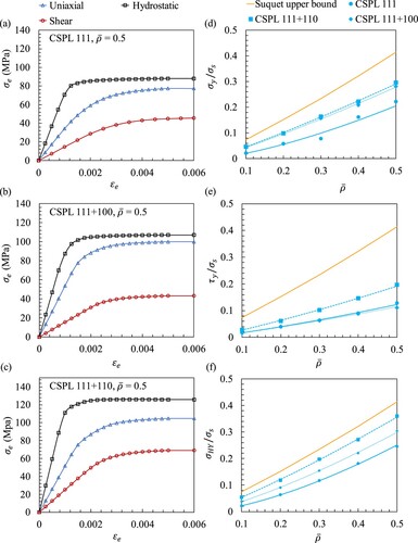
Table 2. A summary of the scaling law parameters of the yield strengths for the CSPLs.
The yield strengths depicted in (d–f) are also compared against the Suquet upper bound () which is defined as the theoretical strength limit of an isotropic lattice material [Citation31,Citation32] as expressed in Equation (7). Besides attaining the HS upper bounds for shear and bulk moduli at low relative densities, (f) demonstrates that the CSPL 111 + 110 design achieves 85% of the Suquet upper bound within the relative density range of 0.1–0.5.
(7)
(7)
4. Constrained-domain topology optimization
With an objective of improving the behaviour of the preceding designs, the constrained-domain topology optimisation procedure is implemented [Citation21]. Generally, an optimisation formulation consists of an objective function and a set of constraints. The objective function defines the purpose of optimisation, for example, minimisation or maximisation of a design response (e.g. stiffness, stress, eigenfrequencies, etc.), while the optimisation constraints impose restrictions on an optimisation task to ensure a feasible outcome, for example, restricting the mass or the volume of the desired output.
The traditional procedure of solving a topology optimisation problem involves discretization of an initial design into a grid of finite elements, where each element is either solid (i.e. relative density of 1) or void (i.e. relative density of 0). Different types of material interpolation schemes are utilised to update the elements relative density, for example, the Solid Isotropic Material with Penalization (SIMP) interpolation scheme is implemented in density-based topology optimisation method to update the elements relative density in a continuous manner [Citation33]. As the introduction of a continuous relative density distribution function restricts the binary nature of the problem, it allows the material’s Young’s modulus at each element to vary continuously according to the following power law:
(8)
(8) where
and
represent the Young’s modulus and the relative density for an eth element, respectively, and
denotes the Young’s modulus for the base material. The parameter
is a penalisation factor which restricts the contribution of elements with intermediate densities (
) to the total stiffness, thus, generating an optimised structure consisting of either solid or void elements.
Herein, the topology optimisation module available in Abaqus/CAE was utilised to minimise the compliance (i.e. maximise the microscopic elastic stiffness) of the proposed CSPLs. The compliance of a structure is defined as the sum of the strain energy of all elements. The mathematical formulation of compliance/strain energy minimisation under volume constraint is expressed as follows:
(9)
(9)
where represents the global compliance,
is a vector consisting of the elements’ relative densities,
is the transpose of an element’s nodal displacement vector,
is the stiffness matrix of an element,
is the global stiffness matrix modulated by
,
is the displacement vector,
is the external force vector,
is the volume of an element, and
is the target mass of optimisation [Citation34].
demonstrates the overall layout of optimising a CSPL 111 + 110 unit cell using the proposed constrained-domain topology optimisation. Note that the same procedure was implemented for the remaining designs. As depicted in (a), the optimisation task was implemented on 1/8th of the unit cell assuming three planes of symmetry, i.e. XZ, XY, and YZ planes. Using a Boolean operation, the 1/8th portion of the unit cell was encased within a solid cube, where the topology optimisation task was implemented on the solid cube, and the 1/8th portion of the unit cell was defined as the frozen region in which the material remains unchanged throughout the optimisation task. Thus, the initial step in the constrained-domain topology optimisation consists of defining the constrained domain (i.e. the frozen region which consists of 1/8th of a unit cell) and the design domain (i.e. the solid cube). In terms of loading and boundary conditions, (a) demonstrates that compressive hydrostatic loading was applied on + X, +Y, and + Z faces of the cube. In order to impose the symmetry of mirror planes, symmetric boundary conditions were applied on -X, -Y, and -Z faces. For example, on the -X face, the translation in X-direction (i.e. is Abaqus) was set to zero and the rotations perpendicular to that were (i.e.
and
) also set to zero. In terms of the optimisation parameters,
and
were set to 0.001 and 3, respectively, with an objective function convergence criterion of 0.001.
Figure 10. The constrained-domain topoloy optimisation procedure for CSPL 111 + 110, showing: (a) applied loading and boundary condition, (b) compliance minimisation throughout the simulation, (c) the raw output of 1/8th of TOCSPL 111 + 110, and (d) the postprocessed output of the complete unit cell of TOCSPL 111 + 110.
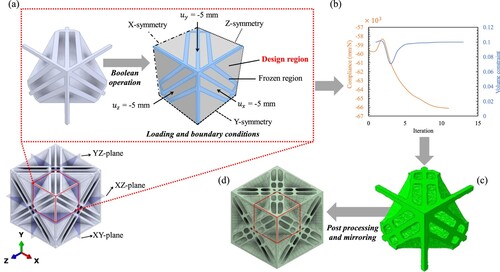
The optimisation tasks were ran using different combinations of volume constraint () and relative density of the frozen region (i.e. initial relative density (
)) to produce outcomes with final relative densities (i.e. relative density of the optimised structure (
)) within 0.1 and 0.5. For example, the optimised solution depicted in (c) with
= 0.4 was generated using a CSPL 111 + 110 unit cell with
= 0.1 and volume constraint of
= 0.2. (b) demonstrates that at the 11th iteration, the compliance had converged and the specified volume constraint was attained. As depicted in (c), the raw output of the optimisation task consists of distorted edges and rough surfaces. The presence of these geometric irregularities would negatively impact the performance of the lattice structures and result in unnecessary local stress concentrations at surface of the geometry. Geometric post-processing and smoothening operations were carried out utilising Ansys SpaceClaim and Autodesk Inventor software to create smooth topologies suitable for FEA analysis and 3D printing. Consequently, the post-processed geometry was mirrored back in the XZ, XY, and YZ planes to produce a complete unit cell as depicted in (d).
summarises the values of and
for each optimisation task that produced a topologically optimised version of the corresponding CSPL (i.e. TOCSPL). The outcomes of these cases are depicted in (a) with the corresponding relative densities. The topology optimisation solutions consisted of adding material to connect the overhang plates, as shown in (d) for the CSPL 111 + 110 lattice, smoothening the sharp edges, as shown in (b) for the CSPL 111 + 100 lattice, or filling the open surfaces, as shown in (b) for the CSPL 111 lattice. Very similar to their non-optimised counterparts, the TOCSPLs turned out to be closed-foam topologies as depicted in (c) where the cross-sectional views of a few designs are demonstrated.
Figure 11. (a) Post-processed topology optimised TOCSPLs at different final relative densities. (b) a few examples demonstrating the benefit of the constrained-domain topology optimisation, such as, filling opened surfaces and smoothening sharp edges. (c) a few examples demonstrating the cross-sectional views of the TOCSPLs.
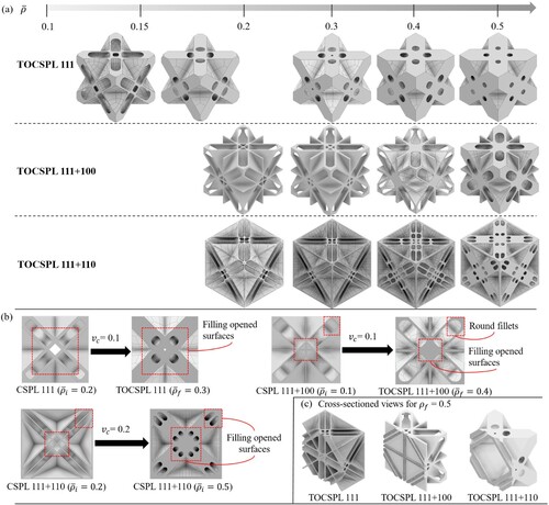
Table 3. A summary of the required initial relative densities and volume constraints to produce the corresponding topologically optimised CSPLs.
4.1. Effective mechanical properties of TOCSPLs
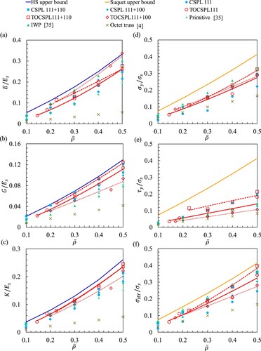
(a–c) illustrate the superiority of the TOCSPLs over the CSPLs in terms of effective normalised uniaxial, shear and bulk moduli, respectively. The elastic moduli of two types of Triply Periodic Minimal Surfaces (TPMS), i.e. the Primitive and I-WP [Citation35], and one type of truss lattice [Citation4], i.e. octet truss, have been considered for the purpose of benchmark comparison. The effective mechanical response of the TOCSPLs were modelled using the micromechanics plugin for Abaqus/CAE, prescribing periodic boundary conditions. (a) demonstrates the competitive performance of the I-WP structure when compared to the remaining ones for , however, beyond this range, the TOCSPL 111 + 100 dominates the performance and exceeds the HS upper bound at
= 0.5. In accordance with the patterns seen in the CSPLs, where the CSPL 111 + 110 performed better than the other designs in terms of shear and bulk moduli, the TOCSPL 111 + 110 also outperformed all the lattice structures studied in terms of these mechanical parameters.
Figure 12. Effective elastic and yielding properties of the TOCSPLs, compared with other types of lattice materials, showing: (a) uniaxial, (b) shear and (c) bulk moduli, and (d) uniaxial, (e) shear and (f) hydrostatic yield strength.
As depicted in , the proper material distribution of TOCSPLs is manifested by the uniform distribution of the Mises stresses resulting from uniaxial, shear, and hydrostatic loading cases when compared to that of CSPLs for the same relative density of 0.4.
Figure 13. Mises stress distribution of the TOCSPLs with = 0.4 as a result of different loading conditions: (a) uniaxial, (b) shear and (c) hydrostatic loading.
In terms of the effective yield strengths, (d–f) show that as a result of topology optimisation, most of TOCSPLs outperformed their non-optimised counterparts for the same relative density. In fact, the TOCSPL 111 + 110 surpassed the remaining lattice materials in terms of shear yield strength for 0.225 0.5. Based on the observed patterns in the CSPLs, where the CSPL 111 + 110 exhibited superior performance compared to other designs in terms of the uniaxial, shear, and bulk moduli, the TOCSPL 111 + 110 likewise surpassed all the lattice structures examined in relation to these mechanical characteristics.
displays the percentage change in the effective mechanical properties of the CSPLs as a result of the constrained-domain topology optimisation. The percentage increase/decrease is represented by the green/red arrows, respectively, where the scale of these arrows reflects the magnitude of the effective mechanical properties of the TOCSPLs. As depicted in (a), the results indicate that for = 0.4, the TOCSPL 111 + 100 exhibited superior performance compared to its non-optimised counterpart (i.e. CSPL 111 + 100), with a notable improvement of 31%. Besides, a few designs exhibited an insignificant improvement in their performance which is mainly attributed to solely smoothening the sharp edges of the original design without adding additional material or connecting overhang geometry. In fact, the optimised designs synthesised from constrained domains with low
and small
did not exhibit substantial enhancement in their performance. In terms of
, the observations on (b) are in synergy with that of (a). In spite of this, at the expense of synthesising a topologically optimised design with improved uniaxial and bulk moduli, the TOCSPL 111 + 100 with
= 0.4 and 0.5 suffered a decrease of 1.33% and 6.31% in terms of shear modulus correspondingly.
Figure 14. Change in the effective mechanical properties between CSPL and TOCSPL lattices, showing: (a) uniaxial, (b) bulk and (c) shear moduli, and (d) uniaxial, (e) hydrostatic and (f) shear yield strength.
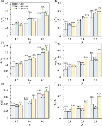
The results displayed in (d–f) indicate that topology optimisation resulted in enhancing the effective yield strengths in the majority of CSPLs. For instance, the uniaxial yield strength of TOCSPL 111 outperformed its non-optimised counterpart by 103% when considering a relative density of 0.3. In contrast, a subset of CSPLs experienced a decrease in their effective yield strengths, as illustrated in (d–f).
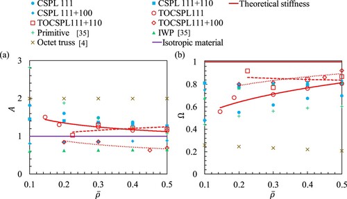
(a) demonstrates that, except for the TOCSPL 111 + 100 and the TOCSPL 111 + 110, the Zener’s index A value of the remaining designs approach unity (i.e. isotropy) with increasing relative density. Moreover, it was found that the 3D elastic anisotropy spatial distributions of TOCSPLs were identical to the ones of CSPLs (i.e. depicted in ). (b) shows the substantial improvement in the total stiffness of the CSPL 111 design as compared to its constrained-domain topology optimised counterpart TOCSPL 111. Although the total stiffness of the remaining TOCSPL lattices exhibit a fluctuating trend, the TOCSPL 111 + 110 with = 0.225 demonstrated the highest total stiffness.
Figure 15. (a) Zener’s index A and (b) the total stiffness Ω of the CSPLs, with their topology optimised counterparts TOCSPLs.
5. Additive manufacturing of samples
Based on the RVE simulation findings, it was observed that various lattice structures demonstrated promising mechanical characteristics, emerging from both the CSPLs and their topologically optimised counterparts TOCSPLs. Consequently, in order to investigate the mechanical properties of these configurations in a tessellated arrangement, they were fabricated with three different relative densities, i.e. = 0.3, 0.4, and 0.5. The Fused Deposition Modeling (FDM) additive manufacturing technique was utilised to produce the lattice structures using the Sindoh 3D WOX1 printer with Acrylonitrile Butadiene Styrene (ABS) material provided in filament form. In this technology, a heated extrusion nozzle is utilised to melt the material and deposit the molten material layer by layer in a predetermined path. At the cost of manufacturing accuracy, FDM produces plate lattice materials composing of closed-cell members without the requirement of perforating the structure for extracting unfused material, which could be a recruitment in laser powered bed fusion (LPBF) additive manufacturing techniques resulting in compromising the stiffness of the printed structure [Citation36]. Furthermore, the CSPLs and the TOCSPLs are self-supporting structures that do not require support material during printing. This is because the constituent plates, except for the orthogonal ones, are oriented at a 45° angle. As a result, the design-to-manufacturing process for the samples is improved, leading to reduced material usage and shorter printing time.
Several samples of CSPL 111 with = 0.3 (refer to (b)) were fabricated with different number of unit cells in order to investigate the effect of periodicity on the mechanical properties, particularly, an array of 2
2
2 (8 unit cells), 3
3
3 (27 unit cells), and 4
4
4 (64 unit cells). It was found that an array of 3
3
3 was sufficient in order to obtain the effective mechanical properties, and hence all of the samples involved in the present study were fabricated with an array of 3
3
3. Further details will be given in section 6.1.
As the surface roughness and the mechanical strength of FDM-printed parts are highly dependent on the process parameters, several print jobs were performed in order to optimise the print quality, the material consumption, and the print duration (). These process parameters are summarised in . A parameter that significantly controls the surface quality of a printed part is the layer height (
), which defines the distance between the deposited layers in the print direction. As depicted in (a), at the cost of longer print duration, using smaller
would slice the highlighted feature of the CSPL 111 + 100 with more layers which results in improving the printing accuracy, thus, strengthening the bonds between the deposited layers. The infill density (
) determines the required amount of material to fill the inner volume of deposited layers. An infill density of 0% refers to a shellular (i.e. empty) geometry while a solid geometry constitutes of
= 100%. Consequently, a solid structure exhibits better mechanical performance at the cost of print duration. For example, (b) depicts the difference in material fullness/emptiness for a cross-section of the CSPL 111 + 100 design. In terms of the nozzle and the bed temperatures, these were set according to the material datasheet provided by Sindoh. The speeds at which the extrusion nozzle travels when extruding filament and when not extruding filament are referred to as the print speed and the travel speed, respectively.
Figure 16. Illustration of the effect of process parameters on the surface roughness and the mechanical strenght of a CSPL 111 + 100 structure: (a) the efffect of layer height on the print duration and layer strenght and (b) the effect of infill density on the print duration.
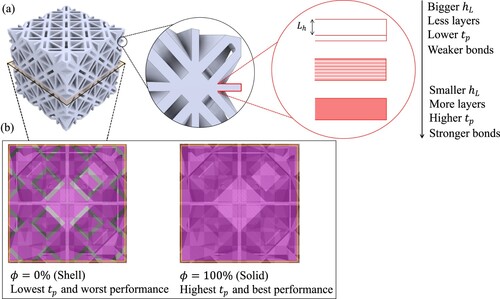
Table 4. A summary of the process parameters utilised in the FDM printer (Sindoh 3D WOX1).
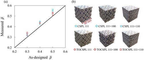
The samples were weighted after printing and their measured relative densities were calculated and compared with the as-designed values, as shown in (a). Note that as each sample was printed twice, the measured relative density represents the average relative densities of two samples. (b) illustrates the additively manufactured samples of CSPLs and TOCSPLs with = 0.5. It was found that the measured relative density of the additively manufactured samples is larger than that of the as-designed relative density. This phenomenon may be related to an inadequate choice of material flow rate which decides the volume of filament deposited throughout the printing process. In this study, the material flow rate was adjusted to 110%, perhaps resulting in an overestimation of the mass of the printed samples.
Figure 17. (a) Comparison between the as-designed and the measured relative densities of the additively manufactured samples and (b) additively manufactured samples with = 0.5.
6. Quasi-static compression experiments
Quasi-static compression experiments were conducted with a strain rate of 0.001/s to investigate the compressive modulus (), the specific energy absorption (SEA), and the uniaxial yield strength (
) of the CSPLs and TOCSPLs tessellated lattice samples. SEA is defined as the energy absorbed per unit mass of material which is calculated by taking the area under a stress–strain diagram up to the densification strain (
):
(10)
(10) Where the densification strain
refers to the onset of cell wall interactions that result in increasing the compressive resistance of a lattice structure [Citation37]. Herein, the densification strain
is defined using the tangent method [Citation37,Citation38] based on the stress–strain curve of the lattice material, where an intersection between the plateau stress line (
) and the tangent line (
) locates
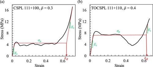
. As an example, (a and b) show the procedure of determining the densification strain
for a bending dominated (i.e. CSPL 111 + 100,
= 0.3) and a stretch-dominated (i.e. TOCSPL 111 + 110,
= 0.4) lattice materials tested within this study.
Figure 18. Applying the tangent method based on the stress-strain curves to determine the densification strain of: (a) CSPL 111 + 100 with
= 0.3, and (b) TOCSPL 111 + 110 with
= 0.4.
6.1. Effective mechanical response
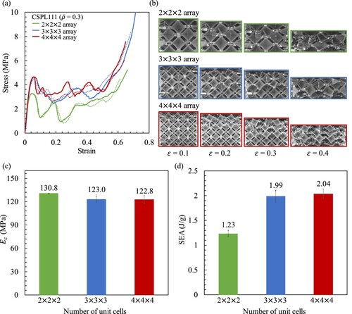
In (a), the stress–strain diagrams of the CSPL 111 with = 0.3 are presented, showcasing several tessellations including 2 × 2 × 2, 3 × 3 × 3, and 4 × 4 × 4. To assess the replicability of the studies, two samples of each tessellation were examined, as depicted by the dotted lines indicating the repeated trials. Correspondingly, (b) depicts the deformation patterns of the tessellated lattice materials at different strains. In the case of the 2
2
2 sample, both layers failed between
= 0.2 and 0.3, whereas in the case of the 4
4
4 array, the initial layer failed at a strain of 0.1, followed by the remaining layers failing successively between
= 0.2 and 0.4. The bar charts in (c and d) illustrate the effect of the number of unit cells on the effective compression modulus
and the SEA of the lattice materials, respectively. Note that the error bars represent the range of two data sets. An increase of 6% and 66.7% is noticed in
and SEA, respectively, when the number of arrays is increased from 2 × 2 × 2 to 3 × 3 × 3. Similarly, a modest increase of 0.16% and 2.5% is observed in
and SEA when the number of arrays is increased from 3 × 3 × 3 to 4 × 4 × 4. Therefore, the findings indicate that employing a 3 × 3 × 3 array is appropriate for capturing the effective mechanical properties.
Figure 19. (a) Experimental stress-strain diagrams of the CSPL 111 with = 0.3 tested at different number of arrays, (b) snapshots of the deformation patterns at different strains, and showing (c) compressive modulus and (d) SEA.
6.2. Experimental results for CSPLs and TOCSPLs
(a–c) show the stress–strain diagrams of CSPLs and TOCSPLs for relative densities of = 0.3, 0.4 and 0.5. The stress–strain behaviours of the topologically optimised lattice materials and their original counterparts were combined in the same graph. (b) demonstrates that the CSPL 111 + 100 and its topologically optimised counterpart exhibited very similar stress–strain behaviours for
= 0.3. and (b) provide the same conclusion by depicting snapshots from the compression experiment at strains of
= 0.2, 0.4, and 0.6 for the same relative density. It can be noticed that both the CSPL 111 + 100 and the TOCSPL 111 + 100 exhibited layer-by-layer failure where the uppermost first and second layers failed successively at strains of 0.2 and 0.4, respectively. Furthermore, (d) shows that at the cost of enhancing the compressive modulus by 3.1% (i.e. from 161 MPa for CSPL 111 + 100 to 166 MPa for TOCSPL 111 + 100), the SEA was reduced by 2.6% (i.e. from 2.27 J/g to 2.21 J/g), as depicted in (e). Besides, (f) demonstrates that for the same samples and relative density, the uniaxial yield strength was improved by 5.8%. However, (b) shows that the TOCSPL 111 + 100 with
= 0.4 and 0.5 exhibited very weak compliance as compared to their original counterparts. For instance, in the case of
= 0.4, the
of the TOCSPL 111 + 100 is greater than that of the CSPL 111 + 100 by 5.8% with a reduction in SEA by 26.7%. Similarly, (c) shows that the TOCSPL 111 + 110 outperformed the CSPL 111 + 110 in terms of the
at the cost of degraded SEA. This is also confirmed by observing the experimental snapshots in and (c) where the CSPL 111 + 110 fails progressively layer-by-layer, while the TOCSPL 111 + 110 exhibit an abrupt failure at strain of 0.2.
Figure 20. Experimental stress-strain digarms of the CSPLs and the TOCSPLs with different relative densities: (a) CSPL 111 and TOCSPL 111, (b) CSPL 111 + 100 and TOCSPL 111 + 100, (c) CSPL 111 + 110 and TOCSPL 111 + 110. Bar charts representing the mechanical properties of CSPLs and TOCSPLs: (d) compressive modulus, (e) SEA, (f) uniaxial yield strength.
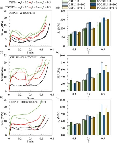
Figure 21. Experimental snapshots and simulation results of quasi-static compression testing for the CSPLs at different strains for the case = 0.3.
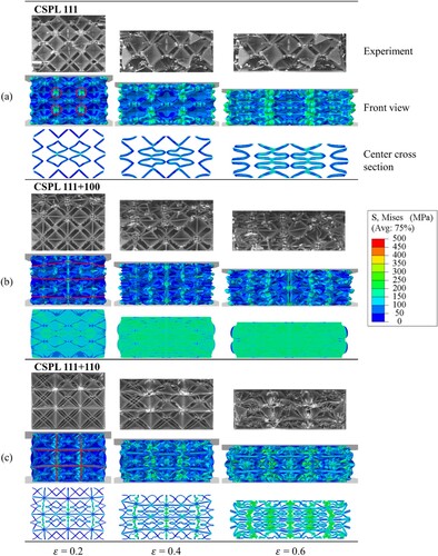
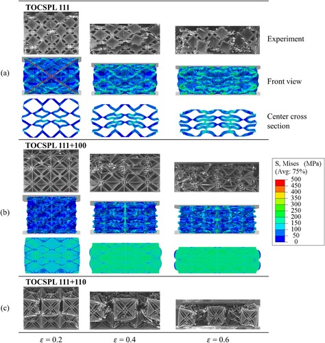
Figure 22. Experimental snapshots and simulation results of quasi-static compression testing for the TOCSPLs at different strains for the case = 0.3.
Moreover, (a) demonstrates that the CSPL 111 and the TOCSPL 111 exhibited very similar stress–strain behaviours for the considered relative densities. In fact, the experimental snapshots in and (a) depict that both designs displayed analogous deformation patterns where local cracks initiated from the centre of the unit cells leading to formation of horizontal global cracks which resulted in a simultaneous breakage of the upper two layers at strain of 0.2. Furthermore, (d and e) demonstrate that the and the SEA of the TOCSPL 111 are greater than that of the CSPL 111 for the considered relative densities, respectively. As a final remark, (d) demonstrates that for the considered relative densities, the TOCSPL 111 + 100 surpassed the remaining samples in terms of compressive modulus. The use of orthogonal plates oriented along the [100] direction improved the resistance to deformation in the direction of the applied load. This clarifies that the CSPL 111 + 100 has a greater compressive modulus compared to both the CSPL 111 and CSPL 111 + 110, across all relative densities.
7. Elastic-plastic compression simulations
In this section, the full elastic-plastic compression simulations of the CSPL and TOCSPL lattices are outlined. In order to obtain the constitutive behaviour of the base material (i.e. ABS plastic), several cubic compression samples, with dimensions 20 × 20 × 20 mm, were additively manufactured and tested in compression. The Young’s modulus was measured 1 GPa and Poisson’s ratio was assumed to be
= 0.35 respectively, which were used to characterise the isotropic elastic behaviour. A J2-plasticity model with isotropic hardening was used to characterise the plastic behaviour for the base material, following the true stress–strain response of the compression test. The lattice structures’ quasi-static compressive behaviour was simulated using the Abaqus/Explicit solver allowing for large deformations. illustrates the model of CSPL 111 with a relative density of 0.3. The model utilised two rigid plates to mimic the platens of the compression machine. The top rigid plate’s translational (
) and rotational (
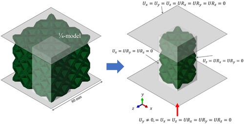
) degrees-of-freedom were fixed in all directions. In contrast, the bottom rigid plate was vertically displaced using a smooth amplitude curve to enable quasi-static loading conditions. The contact interactions between the lattice structure and the rigid plates, as well as the self-contact between the constituent members of the lattice structure, were simulated using a general contact interaction with a friction coefficient of 0.3. The computational efforts were reduced by modelling a quarter model of the lattice structure, taking advantage of the ¼-symmetry, as shown in . The reduced ¼-model was meshed using a 10-node modified quadratic tetrahedron element (C3D10M) with a total of about 250 000 elements, providing at least three elements across the plate thickness. The reduced ¼ model was meshed with a total of 222 500 elements, which closely matched those of the full model, thereby supporting the adoption of the ¼-model.
Figure 23. Model for elastic-plastic compression simulations (CSPL 111, = 0.3).
and illustrate the simulated deformation patterns and the Mises stress contours for the CSPLs and the TOCSPLs at various strains for the case = 0.3. In the case of CSPL 111, in (a), the stresses are concentrated at the intersection of the unit cells, which is indicated by the circular shapes. The experimental snapshots validate this phenomenon, as numerous localised cracks propagated across the entirety of the structure. The centre cross-sectional views illustrate that the CSPL 111 design’s simplicity and the lack of constituent plates in the [110] or [111] orientations cause significant bending of the structure at high strains. When considering CSPL 111 + 100 in (b), the introduction of orthogonal plates results in the spatial redistribution of stresses and alleviates the stress concentration observed in the deformation pattern at a strain of 0.4. Moreover, the cross-sectional views demonstrate that the inclusion of orthogonal plates increased the structural connection and enhanced the ability to resist deformation in the direction of loading. This elucidates the higher compressive modulus of the CSPL 111 + 100 in comparison to the CSPL 111 and CSPL 111 + 110, across all relative densities, as illustrated in (d). In the case of CSPL 111 + 110 in (c), incorporating constituent plates in the [110] orientation enhanced load transfer between the cell walls. This improvement was achieved by increasing the number of plates, which enhances material connectivity in the structure. As a result, the strength and specific energy absorption of the CSPL 111 design were improved across a range of relative densities, as shown in (f and e), respectively. In contrast to the stress concentration observed in the deformation pattern of CSPL 111 in and (a) reveals the appearance of shear bands in the deformation profile of TOCSPL 111 at a strain of 0.2, which is further corroborated by the experimental snapshots. At the same strain of 0.2, the TOCSPL 111 + 100 in (b) exhibits reduced stress patterns in comparison to its non-optimised counterparts, e.g. CSPL 111 + 100 in (b), which highlights the advantages of employing topology optimisation.
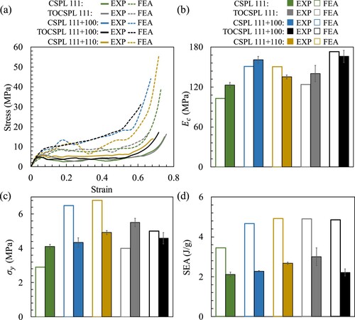
(a) shows the stress–strain diagrams obtained from both the FEA and experimental results for the case = 0.3, and the corresponding compression modulus, yield strength and specific energy absorption (SEA) are shown in (b–d), respectively. The comparison between FEA and experimental results reveals a notable agreement in the compressive modulus in (b), but discrepancies in yield strengths and SEA in (c and d), respectively. These disparities are primarily attributed to the absence of consideration for manufacturing defects in the computational model, such as local porosity, surface roughness, and residual stresses. These outcomes are typically expected, given that the computational model are based on perfect CAD geometries without accounting for anisotropies resulting from the manufacturing process [Citation39,Citation40]. The absence of damage models in the computational simulations further limits the precise representation of microcrack formation, progress of damage and subsequent material failure, which are present in the experiments [Citation41–44].
Figure 24. (a) Experimental and numerical stress-strain diagrams of the CSPLs and the TOCSPLs for the case = 0.3. Bar charts comparing the experimental and numerical mechanical properties of the CSPLs, showing (b) compressive modulus, (c) uniaxial yield strength, and (d) SEA.
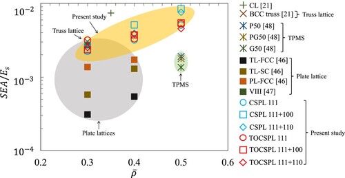
8. Performance benchmark and discussion
present comparative evaluations of several lattice materials obtained from the literature [Citation21,Citation45–Citation51], in addition to the designs proposed in this work. The comparison is based on experimentally determined mechanical properties: normalised elastic modulus (), normalised yield strength
(), and normalised energy absorption
(). While the normalisation of mechanical properties helps to address the inconsistencies resulting from variations in the performance of the base material, the mechanical strength of lattice materials remains dependent on the accuracy and precision of the additive manufacturing process. and demonstrate the comparative advantages of the lattice materials presented within this study in relation to a group of honeycomb, truss, TPMS, and plate lattice materials, specifically in terms of elastic and yield strength, respectively. As observed, the prominence of buckling in the solid plate-like disks of CSPLs and TOCSPLs lessens as the relative densities grow, consequently, their performance surpasses that of truss and TPMS structures by a considerable degree. Besides, illustrates the superiority of CSPL 111 + 100 in terms of energy absorption in comparison to a collection of TPMS and plate-based lattice materials with relative densities of
= 0.4 and 0.5. The outlined comparative assessment highlights the potential value of the proposed topologies for applications involving load-bearing and impact absorption.
Figure 25. Comparing lattice materials from the literature and designs proposed in this work using experimentally determined normalised elastic modulus.
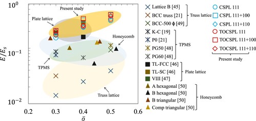
Figure 26. Comparing lattice materials from the literature and designs proposed in this work using experimentally determined normalised yield strength.
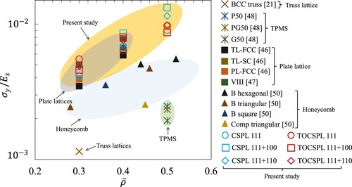
Figure 27. Comparing lattice materials from the literature and designs proposed in this work using experimentally determined normalised energy absorption.
9. Conclusions
This study introduced the design of innovative Cuboidal Spherical Plate Lattice (CSPL) materials comprising of plate-like solid disks. With an objective of improving the design of the proposed topologies, the constrained-domain topology optimisation strategy was implemented to render new geometries with enhanced mechanical response under prescribed loading and boundary conditions. For the same relative density, the topologically optimised geometries (i.e. TOCSPLs) exhibited increased uniaxial, shear, and bulk moduli with an increase of 31%, 14%, and 36%, when compared to the CSPLs, respectively. Furthermore, there was a notable enhancement in the uniaxial, shear, and hydrostatic yield strengths, with improvements of 103%, 55%, and 62% correspondingly. Besides, many of the proposed topologies attained the Hashin-Shtrikman upper bound (i.e. theoretical elastic limit) while simultaneously performing within 85% of the Suquet upper bound (i.e. theoretical strength limit). For a comprehensive mechanical characterisation, the CSPLs and the TOCSPLs were additively manufactured through Fused Deposition Modeling (FDM) technique then subjected to compression testing. The experimental outcomes revealed the superiority of the proposed designs in terms of uniaxial modulus, yield strength, and energy absorption when compared to that of several lattices from literature, including, honeycomb, TPMS, truss-, and plate-based designs.
The compression behaviour of the generated lattices were investigated numerically by studying their elastic-plastic quasi-static compressive behaviour. However, the analysis was constrained as it did not account for the anisotropies generated during the manufacturing process. The inclusion of a damage initiation criterion could enhance the model’s predictive accuracy related to the energy absorption capabilities of these lattice materials. Considering the noteworthy energy absorption demonstrated by the proposed lattice materials under quasi-static loading, future research should prioritise exploring their impact absorption capabilities under dynamic loading condition. This could render them valuable in applications where improved impact properties are required. The exceptional performance of the lattice materials suggested in this study provides strong justification for their utilisation in applications that demand both load-bearing and impact absorption capabilities.
Acknowledgement
The authors acknowledge the financial support provided by the Khalifa University under Award No. RCII-2019-003.
Disclosure statement
No potential conflict of interest was reported by the author(s).
Data availability statement
Data will be made available on request from the authors.
Additional information
Funding
References
- Leonhardt U. Optical conformal mapping. Science (80-). 2006;312(5781):1777–1780. doi:10.1126/science.1126493
- Ha CS, Lakes RS, Plesha ME. Cubic negative stiffness lattice structure for energy absorption: Numerical and experimental studies. Int J Solids Struct. 2019;178–179:127–135. doi:10.1016/j.ijsolstr.2019.06.024
- Bertoldi K, Reis PM, Willshaw S, et al. Negative poisson’s ratio behavior induced by an elastic instability. Adv Mater. 2010;22(3):361–366. doi:10.1002/adma.200901956
- Deshpande VS, Fleck NA, Ashby MF. Effective properties of the octet-truss lattice material. J Mech Phys Solids. 2001;49:1747–1769. doi:10.1016/S0022-5096(01)00010-2
- Al-Ketan O, Abu Al-Rub RK. Multifunctional mechanical metamaterials based on triply periodic minimal surface lattices. Adv Eng Mater. 2019;21(10). doi:10.1002/adem.201900524
- Berger JB, Wadley HNG, McMeeking RM. Mechanical metamaterials at the theoretical limit of isotropic elastic stiffness. Nature. 2017;543(7646):533–537. doi:10.1038/nature21075
- Baghous N, Barsoum I, Abu Al-Rub RK. The effect of Lode parameter on the yield surface of Schoen’s IWP triply periodic minimal surface lattice. Mech Mater. 2022;175:104473. doi:10.1016/j.mechmat.2022.104473
- Baghous N, Barsoum I, Abu Al-Rub RK. Generalized yield surface for sheet-based triply periodic minimal surface lattices. Int J Mech Sci. 2023;252:108370. doi:10.1016/j.ijmecsci.2023.108370
- Ahmed N, Barsoum I, Abu Al-Rub RK. Numerical investigation on the effect of residual stresses on the effective mechanical properties of 3D-printed TPMS lattices. Metals (Basel). 2022;12(8):1–20. doi:10.3390/met12081344
- Ahmed N, Barsoum I, Al-Rub RKA. Numerical investigation of residual stresses in thin-walled additively manufactured structures from selective laser melting. Heliyon. 2023;9(9):e19385. doi:10.1016/j.heliyon.2023.e19385
- Altamimi S, Lee DW, Barsoum I, et al. On stiffness, strength, anisotropy, and buckling of 30 strut-based lattices with cubic crystal structures. Adv Eng Mater. 2022;24(7). doi:10.1002/adem.202101379
- Viswanath A, Khan KA, Barsoum I. Design of novel isosurface strut-based lattice structures: Effective stiffness, strength, anisotropy and fatigue properties. Mater Des. 2022;224:111293. doi:10.1016/j.matdes.2022.111293
- Dong L, Deshpande V, Wadley H. Mechanical response of Ti-6Al-4V octet-truss lattice structures. Int J Solids Struct. 2015;60–61:107–124. doi:10.1016/j.ijsolstr.2015.02.020
- Alomar Z, Concli F. Compressive behavior assessment of a newly developed circular cell-based lattice structure. Mater Des. 2021;205:109716. doi:10.1016/j.matdes.2021.109716
- Tancogne-Dejean T, Diamantopoulou M, Gorji MB, et al. 3D plate-lattices: an emerging class of low-density metamaterial exhibiting optimal isotropic stiffness. Adv Mater. 2018;30(45):1–6. doi:10.1002/adma.201803334
- Sigmund O, Maute K. Topology optimization approaches. Struct Multidiscip Optim. 2013;48(6):1031–1055. doi:10.1007/s00158-013-0978-6
- Bendsøe MP, Lund E, Olhoff N, et al. Topology optimization – broadening the areas of application. Control Cybern. 2005;34(1):7–36.
- Xiao Z, Yang Y, Xiao R, et al. Evaluation of topology-optimized lattice structures manufactured via selective laser melting. Mater Des. 2018;143:27–37. doi:10.1016/j.matdes.2018.01.023
- Duan S, Xi L, Wen W, et al. Mechanical performance of topology-optimized 3D lattice materials manufactured via selective laser sintering. Compos Struct. 2020;238(January):111985. doi:10.1016/j.compstruct.2020.111985
- Zeng Q, Duan S, Zhao Z, et al. Inverse design of energy-absorbing metamaterials by topology optimization. Adv Sci. 2022:1–10. doi:10.1002/advs.202204977
- Alawwa F, Barsoum I, Al-Rub RKA. Modeling, testing, and optimization of novel lattice structures for enhanced mechanical performance. Mech Adv Mater Struct. 2023:2262987. doi:10.1080/15376494.2023.2262987
- Xia Z, Zhang Y, Ellyin F. A unified periodical boundary conditions for representative volume elements of composites and applications. Int J Solids Struct. 2003;40(8):1907–1921. doi:10.1016/S0020-7683(03)00024-6
- Xia Z, Zhou C, Yong Q, et al. On selection of repeated unit cell model and application of unified periodic boundary conditions in micro-mechanical analysis of composites. Int J Solids Struct. 2006;43(2):266–278. doi:10.1016/j.ijsolstr.2005.03.055
- Abu Al-Rub RK, Lee D-W, Khan KA, et al. Effective anisotropic elastic and plastic yield properties of periodic foams derived from triply periodic Schoen’s I-WP minimal surface. J Eng Mech. 2020;146(5):1–19. doi:10.1061/(asce)em.1943-7889.0001759
- Ranganathan SI, Ostoja-Starzewski M. Universal elastic anisotropy index. Phys Rev Lett. Aug 2008;101(5). doi:10.1103/PhysRevLett.101.055504
- Hashin Z, Shtrikman S. A variational approach to the theory of the elastic behaviour of multiphase materials. J Mech Phys Solids. 1963;11(2):127–140. doi:10.1016/0022-5096(63)90060-7
- Gibson LJ, Ashby MF. Cellular solids: structure and properties. 2nd ed. UK; 1997. doi:10.1017/CBO9781139878326
- Fleck NA, Deshpande VS, Ashby MF. Micro-architectured materials: past, present and future. Proc R Soc A Math Phys Eng Sci. 2010;466(2121):2495–2516. doi:10.1098/rspa.2010.0215
- Snyder JP, Voxland PM. An album of map projections. 1989. doi:10.3133/pp1453
- Ran Z, Zou C, Wei Z, et al. VELAS: an open-source toolbox for visualization and analysis of elastic anisotropy. Comput Phys Commun. 2023;283:108540. doi:10.1016/j.cpc.2022.108540
- Suquet PM. Overall potentials and extremal surfaces of power law or ideally plastic composites. J Mech Phys Solids. 1993;41(6):981–1002. doi:10.1016/0022-5096(93)90051-G
- Crook C, Bauer J, Guell Izard A, et al. Plate-nanolattices at the theoretical limit of stiffness and strength. Nat Commun. 2020;11(1):1–11. doi:10.1038/s41467-020-15434-2
- Bendsoe MP, Kikuchi N. Generating optimal topologies in structural design using a homogenization method. Comput Methods Appl Mech Eng. 1988;71:197–224. doi:10.1016/0045-7825(88)90086-2
- Almesmari A, Alagha AN, Naji MM, et al. Recent advancements in design optimization of lattice structured materials. Adv Eng Mater. 2023;25. doi:10.1002/adem.202201780
- Abueidda DW, Abu Al-Rub RK, Dalaq AS, et al. Effective conductivities and elastic moduli of novel foams with triply periodic minimal surfaces. Mech Mater. 2016;95:102–115. doi:10.1016/j.mechmat.2016.01.004
- Almesmari A, Sheikh-ahmad J, Jarrar F, et al. Optimizing the specific mechanical properties of lattice structures fabricated by material extrusion additive manufacturing. J Mater Res Technol. 2022;22:1821–1838. doi:10.1016/j.jmrt.2022.12.024
- Li QM, Magkiriadis I, Harrigan JJ. Compressive strain at the onset of densification of cellular solids. J Cell Plast. 2006;42(5):371–392. doi:10.1177/0021955X06063519
- Miltz J, Gruenbaum G. Evaluation of cushioning properties of plastic foams from compressive measurements. Polym Eng Sci. 1981;21(15):1010–1014. doi:10.1002/pen.760211505
- Alomar Z, Concli F. A review of the selective laser melting lattice structures and their numerical models. Adv Eng Mater. 2020;22(12):1–17. doi:10.1002/adem.202000611
- Concli F, Gilioli A. Numerical and experimental assessment of the mechanical properties of 3D printed 18-Ni300 steel trabecular structures produced by Selective Laser Melting–a lean design approach. Virtual Phys Prototyp. 2019;14(3):267–276. doi:10.1080/17452759.2019.1565596
- Concli F, Gilioli A, Nalli F. Experimental–numerical assessment of ductile failure of additive manufacturing selective laser melting reticular structures made of Al A357. Proc Inst Mech Eng Part C J Mech Eng Sci. 2021;235(10):1909–1916. doi:10.1177/0954406219832333
- Nalli F, Cortese L, Concli F. Ductile damage assessment of Ti6Al4 V, 17-4PH and AlSi10Mg for additive manufacturing. Eng Fract Mech. 2021;241(November 2020):107395. doi:10.1016/j.engfracmech.2020.107395
- Concli F, Gilioli A. Numerical and experimental assessment of the static behavior of 3D printed reticular Al structures produced by Selective Laser Melting: progressive damage and failure. Procedia Struct Integr. 2018;12:204–212. doi:10.1016/j.prostr.2018.11.094
- Abou-Ali AM, Al-Ketan O, Lee DW, et al. Mechanical behavior of polymeric selective laser sintered ligament and sheet based lattices of triply periodic minimal surface architectures. Mater Des. 2020;196:109100. doi:10.1016/j.matdes.2020.109100
- Challapalli A, Patel D, Li G. Inverse machine learning framework for optimizing lightweight metamaterials. Mater Des. 2021;208:109937. doi:10.1016/j.matdes.2021.109937
- Li T, Jarrar F, Abu Al-Rub R, et al. Additive manufactured semi-plate lattice materials with high stiffness, strength and toughness. Int J Solids Struct. 2021;230–231:111153. doi:10.1016/j.ijsolstr.2021.111153
- Fan B, Xu Z, Lin Y, et al. Mechanical properties of a novel two-phase hybrid plate-lattice metamaterial. Mech Adv Mater Struct. 2023;30(23):4752–4763. doi:10.1080/15376494.2022.2104974
- Yu A, Zhang C, Xu W, et al. Additive manufacturing of multi-morphology graded titanium scaffolds for bone implant applications. J Mater Sci Technol. 2023;139:47–58. doi:10.1016/j.jmst.2022.07.035
- Egan PF, Khatri NR, Parab MA, et al. Mechanics of 3D-printed polymer lattices with varied design and processing strategies. Polymers (Basel). 2022;14(24):5515. doi:10.3390/polym14245515
- León-Becerra J, González-Estrada OA, Quiroga J. Effect of relative density in in-plane mechanical properties of common 3D-printed polylactic acid lattice structures. ACS Omega. Nov 2021;6(44):29830–29838. doi:10.1021/acsomega.1c04295
- Almesmari A, Baghous N, Ejeh CJ, et al. Review of additively manufactured polymeric metamaterials: design, fabrication, testing and modeling. Polymers (Basel). 2023;15(19):3858. doi:10.3390/polym15193858