
 ?Mathematical formulae have been encoded as MathML and are displayed in this HTML version using MathJax in order to improve their display. Uncheck the box to turn MathJax off. This feature requires Javascript. Click on a formula to zoom.
ABSTRACT
The cuttlebone is known for its ability to possess high specific stiffness, progressive failure and lightweight from the porous chambered structure. Inspired by the microstructural characteristics of cuttlebone and incorporating the wall gradient design, a series of double-asymmetric honeycombs were designed and processed by LPBF. Results indicated that bionic structural units with the junction design can maintain the integrity of the residual parts after local buckling and failure, improving the load-bearing capacity. The double-asymmetric honeycomb with gradation parameter α = 2/3 achieved a maximum specific compressive strength of 70.64 MPa cm3/g. As α decreases, there is an increase in specific energy absorption and a narrowing of the hysteresis loop. The as-build honeycomb had undergone stress-induced martensite transformation during compression. The dissipated mechanical energy (ME) decreased with the increasing cycle number and the decreasing α. The results provide design guidelines and process strategies for developing high-performance honeycombs.
1. Introduction
Porous materials, also named cellular materials, are constructed upon a fixed skeletal framework containing pores. These lightweight materials excel in load bearing and energy absorption, garnering tremendous interest across diverse fields like aerospace, automotive, defense, and others [Citation1–3]. Honeycomb structures, formed by an array of unit cells with regular thin walls, are a commonly used type of porous material [Citation4]. Much research has examined the mechanical behaviour of various honeycomb architectures under quasi-static and impact loading [Citation5]. Numerous cell configurations have been investigated, such as triangular [Citation6], circular [Citation7], square [Citation8], octagon [Citation9], Kagome [Citation10], and more. The high tailorability of honeycombs enables meeting multifarious functional demands posed by practical applications. Understanding links between honeycomb architecture and deformation mechanisms under loading is critical for designing protective systems with high load-bearing and energy absorption capabilities [Citation11]. Crucial considerations include the geometric architecture and material selection, which in turn may be influenced by the configuration and spatial layouts of the unit cells, as well as processing history [Citation12].
Adjusting cross-sectional profiles presents an effective approach for enhancing honeycomb mechanical properties [Citation13]. Replacing regular walls with diverse cellular microstructures (e.g. hexagonal, triangular, sandwich micro-cells) constructed several hierarchical honeycombs with enhanced mechanical properties [Citation14]. Mathematical functions and curves afford control over honeycomb cross-sectional profiles by tuning parameters, enabling designers to obtain varied shapes [Citation15]. Compared to straight-walled honeycombs, curved-walled designs substantially increased load-bearing capacity and improved specific energy absorption by 25–33.8% [Citation15, Citation16]. Bioinspired architectures were suggested to enable further optimisation over traditionally improved honeycombs. For example, bamboo-inspired circular honeycomb tubular structures exhibited a specific energy absorption of 29.3 J/g under dynamic impact [Citation17]. Drawing from lotus root, horsetail and honeycomb, Wu et al. [Citation18] developed a novel hybrid bio-inspired honeycomb with substantially improved energy absorption over single-walled structures. Recently, the cuttlebone has garnered interest for its high specific stiffness, progressive failure and lightweight structure [Citation19, Citation20]. Its asymmetric corrugated walls can localise damage by controlling maximum stresses, enhancing energy dissipation [Citation21, Citation19]. Mimicking the corrugated architecture of cuttlebone presents a promising route to enhance traditional honeycombs by tuning cross-sectional profiles. In addition to in-plane tailoring, selecting optimal wall materials and thicknesses could further enable lightweight, high-performance designs [Citation22]. Incorporating gradient walls is an effective strategy to further augment honeycomb energy absorption [Citation4]. For example, architected gradient honeycombs can achieve up to 90% energy absorption efficiency by inducing a transition from brittle to progressive damage modes [Citation23]. The promising bioinspired architectures and gradient design concepts presented above untapped opportunities to further advance honeycomb bearing capabilities and performance boundaries. This motivates conceptualising an integrated approach that synergistically combines these strategies to engineer mechanically sturdy honeycombs with excellent energy absorption capabilities.
Complex honeycombs with tailored cross-sectional profiles were challenging and often impossible to manufacture using traditional techniques [Citation23]. Laser powder bed fusion (LPBF) enables precise control over the intricate internal architecture of complex honeycombs through its layered processing and layer by layer deposition [Citation4], facilitating fabrication of sophisticated honeycombs with spatially tailored geometries [Citation23]. Additionally, the material properties of base materials in additive manufacturing structures influence deformation behaviour and failure mechanisms, controlling load-bearing and energy absorption performance [Citation24]. Nickel-titanium (NiTi) shape memory alloys (SMAs) have been extensively studied for additively manufactured porous structures due to their favourable mechanical properties, excellent fatigue resistance, and unique shape memory effect (SME) and pseudoelasticity (PE) [Citation25]. Combining NiTi and architected structures provides a feasible solution for designing and additively manufacturing reusable energy absorbing materials. However, nonuniform stress distributions in traditional NiTi structures prevented complete martensitic transformation, limiting the energy absorption potential of NiTi [Citation26]. Although further increasing loads could have promoted martensite transformation, structures may have lost stability and configurations due to plastic deformation and damage in stress concentration regions [Citation27]. Therefore, to fully utilise NiTi alloy properties and achieve tailored honeycomb performance, it was essential to systematically understand relationships between honeycomb geometry and mechanical behaviour.
Inspired by the triple junction characteristics and asymmetric walls of cuttlebone and incorporating a gradient design of wall thicknesses, a series of double-asymmetric honeycombs were designed and processed by LPBF. The formability of LPBF-processed double-asymmetric honeycombs structures was analyzed. Compressive experiments were conducted to assess the mechanical properties and deformation mechanisms of bionic unit cells and double-asymmetric honeycombs. The morphologies and the phase constitution after compression tests of double-asymmetric honeycombs were analyzed. Finally, the superelasticities of double-asymmetric honeycombs were further evaluated.
2. Material and methods
2.1. Microstructure of the cuttlebone
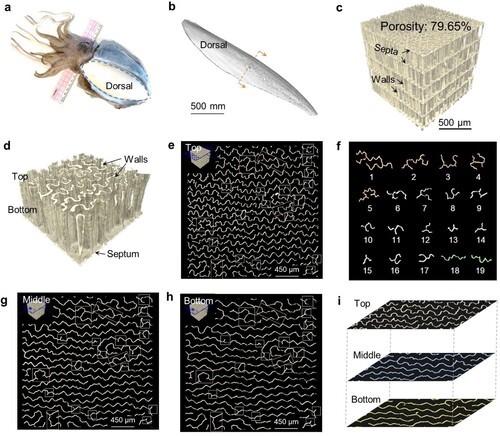
The cuttlebone (circled with a dashed yellow line in a), located dorsally in the cuttlefish (Sepiella japonica), had a spoon-handle shape (b). The cuttlebone contained a porous chambered structure inside, with up to 79.65% porosity (c). The cuttlefish adjusted buoyancy by controlling fluid flow into and out of the porous chambers [Citation28]. These porous chambers comprised multiple layered chambers, where each layer was separated by septa and supported by numerous uniquely designed vertical corrugated walls (d). Labyrinthine patterns were observed at the top (e), middle (g), and bottom (h) of the vertical corrugated walls within a single chambered layer. Double triple-junction (numbers 1–5 in f) and triple-junction (numbers 6–17 in f) patterns were identified in e, circled in yellow and white boxes, respectively. These junction features were also observed at the corresponding positions in the middle and bottom labyrinthine patterns (g and h). Notably, the vertical walls comprising the junctions were corrugated (numbers 18 and 19 in f). Moreover, overlaying the cross-sectional profiles at the top, middle, and bottom of a chambered layer showed the vertical walls gradually increased in waviness from bottom to top (i). The cross-sectional profile of the bottom vertical wall is similar to a sine wave (h), while the cross-sectional profile of the top vertical wall can be simplified as a hybrid wave formed by the superposition of the bottom sine wave and a sine wave with smaller periods (e).
Figure 1. Microstructure of the cuttlebone. (a) Images of the cuttlefish and (b) the cuttlebone, (c) the micro-CT image of the cuttlebone’s multilayer structure, (d) a single chambered layer of cuttlebone; the labyrinthine patterns of the cross-sections at (e) the top, (g) the middle, and (h) the bottom position in the single layer structure, (f) walls with junctions extracted from (e) the top position; (i) the overlaying the cross-sectional profiles at the top, middle and bottom position of a chambered layer.
2.2. Structural design strategy and geometric configurations
Based on the analysis of cuttlebone structure in the previous section, the waviness of the vertical wall gradually increases from bottom to top. the contour at the bottom could be expressed as a sine wave (i):
(1)
(1) The contour at the top could be represented as a blended sine curve:
(2)
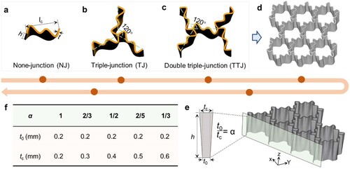
(2) where A, B, C, and D were constants with values of 0.5, 1, 0.5, and 3, respectively. The none-junction (NJ) structure inspired by the cuttlebone was designed by extruding along the height direction using the two curves (a). The NJ thickness was set at 0.2 mm. Rotating and arraying NJ formed triple-junction (TJ) and double triple-junction (TTJ) structures similar to the cuttlebone (b and c). Mixing TJ and TTJ into an array to form the asymmetric honeycomb (d). Furthermore, by designing the thickness gradient of the asymmetric array honeycomb, a series of double-asymmetric honeycombs were obtained (e and f). The top profile had a variational thickness tc and the bottom (z = 0) had a constant minimum thickness t0 (f). The wall thickness of double-asymmetric honeycombs at any z was given by:
(3)
(3) where α was the gradation parameter such that 0 <
≤ 1, h was the height of the double-asymmetric honeycombs set at 6 mm. When α = 1, the double-asymmetric honeycomb is the asymmetric honeycomb.
Figure 2. (a) The none-junction (NJ), (b) the triple-junction (TJ), and (c) the double triple-junction (TTJ) structures. (d) The asymmetric honeycomb. The double-asymmetric honeycombs with wall thickness gradient design: (e) Geometrical tailoring schemes and (f) design parameters for wall thickness gradient.
2.3. Laser powder bed fusion process and characterisation
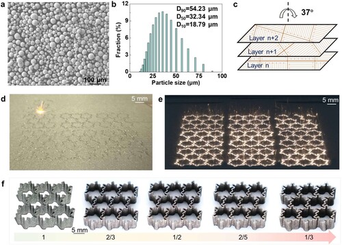
The designed samples were manufactured using a self-developed LPBF system, using pre-alloyed NiTi alloy powder. a depicts the powder morphologies, revealing their nearly spherical shape. The particle size ranged from 0.02 to 89.33 μm and median diameter D50 was 32.34 μm (b). In order to reduce the residual stress, the ‘island’ and ‘rotation’ scanning strategies were applied, as depicted in c. The manufacturing procedures were established following the methodology described in our previous publication [Citation29]. The processing parameters were set with a laser power (P) of 125 W, scanning speed (v) of 1400 mm/s, powder layer thickness (h) of 30 μm, and hatch spacing (t) of 50 μm. d demonstrates the LPBF process employed for fabricating the double-asymmetric honeycombs. e depicts long-exposure images illustrating the interaction between the laser beam and the NiTi powder. Upon completion of the LPBF process, all samples were separated from the substrate using electric discharge wire-cutting technology. The samples were washed in an ultrasonic cleaner with alcohol for 10 min before morphological and mechanical characterisation (f).
Figure 3. (a) Morphology and (b) particle size distribution of the NiTi powder, (c) the ‘island’ and ‘rotation’ scanning strategies, (d) LPBF process of the double-asymmetric honeycombs, (e) Long-exposure images of laser-powder interaction, (f) the as-build double-asymmetric honeycombs.
The cuttlebone sample was 3D reconstructed using a Micro-CT scanner (d2, Diondo, Germany) at a voltage of 90 kV and a voxel size of 7 μm. The phase constitution of the samples before and after compression tests was determined using X-ray diffraction, employing a Thermo ScientificTM ARLTM X’TRA X-ray diffractometer and Cu-Kα radiation (λ = 0.15418 nm). The scanning angle 2θ ranged from 20° to 90° at a speed of 4°/min. The morphologies of the LPBF-processed samples were characterised using a field emission SEM (TESCAN LYRA3, Czech Republic).
Compression and superelasticity tests were performed using a CMT5205 testing machine (MTS Industrial System, China) at a strain rate of 1 mm/min. The superelasticity test is conducted in a constant temperature environment of 50°C (above the austenite finish temperature). Energy absorption (EA) performance was evaluated in accordance with ISO 13314:2011 standards [Citation30], which recommended an upper limit of 50% compressive strain for EA calculation. EA was defined as the area under the compressive stress–strain curve, and determined by [Citation30]:
(4)
(4) where σ is the compressive stress (MPa), ϵ0 is the upper limit of the compressive strain (50%). Specific energy absorption (SEA), accounting for structural density, was used to further evaluate energy absorption as [Citation31, Citation32]:
(5)
(5) where ρnomi is the nominal relative density, which is determined by the ratio between the volume of the designed model and the spatial region of the structure; ρs is the density of the base material.
Dynamic explicit finite element (FE) simulations were carried out in ABAQUS 2019 to elucidate the mechanical behaviour of LPBF-processed structures under compression. A mean mesh element size of 0.2 mm was employed to ensure both high accuracy and computational efficiency. The numerical models and material properties are detailed in our previous work [Citation26].
3. Results and discussion
3.1. Mechanical properties of unit cell structures
The contribution of junctions present in the biomimetic structures was estimated by testing the compression mechanical properties of the LPBF-processed none-junction (NJ), triple-junction (TJ) and double triple-junction (TTJ) structures. To exclude the influence of mass on their mechanical properties, specific compressive strength (SCS)-strain curves of the three types of unit cell structures were plotted for comparison (a). The three SCS-strain curves initially increased linearly, exhibiting elastic properties. With increasing strain, the specific compressive strength continued to increase as the SCS-strain curves deviated from the linear response and transitioned to a nonlinear regime. Due to continuous structural deformation, the specific compressive strength increases rate (slope) decreased until a peak indicating maximum specific compressive strength was reached. At this stage, it corresponds to the buckling deformation stage of three structures (d). The highest maximum specific compressive strength of 9.85 MPa·cm3/g was possessed by the double triple-junction structure among the three types of unit cell structures, followed by the triple-junction (8.51 MPa cm3/g) and none-junction (6.82 MPa · cm3/g) structures (b). It was indicated that the junction design of the bionic thin-walled structures was beneficial for their load-bearing capacity. Structural failure was indicated at this stage as all three SCS-strain curves exhibited significant drops after reaching the maximum specific compressive strength. Due to its inability to maintain vertical support, the failed none-junction structure could no longer bear load during subsequent compression. However, the remaining parts of the triple-junction and double triple-junction structures could continue bearing loads after failure. Mainly attributed to multiple structural collapses, periodic peaks were observed in the SCS-strain curves of the triple-junction and double triple-junction structures. On the one hand, TTJ has more junctions (NJ, TJ, and TTJ have 0, 1, and 2 junctions, respectively) compared to others. On the other hand, the ratio of length to thickness of TTJ is small under the same unit cell size. The smaller this ratio is, the less prone the honeycomb wall is to buckle, resulting in higher SCS and multiple structural collapses. An increasing trend in energy absorption (EA) for the three structures with increasing compressive strain is shown in c. The increase in EA slowed significantly, corresponding to the dramatic drop stage of the SCS-strain curves. After failure, it is notable that the non-junction lost the energy absorption ability structure, while the triple-junction and double triple-junction structures maintained the ability to continue absorbing energy. Therefore, the junction design of the bionic thin-walled structures was beneficial from an energy absorption perspective.
Figure 4. (a) Specific compressive strength (SCS)-strain curves of three LPBF-processed unit cell structures, (b) the maximum SCS of different structures, (c) the energy absorption (EA) versus the strain; (d) structural deformation characteristics of three LPBF-processed unit cell structures; (e) Experimental and simulated force-displacement curves of double triple-junction structure, (f) structural deformation characteristics and (g) stress distribution near failure strain.
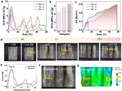
The force-displacement curves from experiment and simulation for the double triple-junction structure showed that the simulation results agreed well with the experimental results (e), verifying the accuracy of the numerical model and providing a reliable method for revealing deformation mechanisms and mechanical properties [Citation33]. Near the bottom of the sample, local buckling was observed in the experimental results (at 7.10% strain), which was marked with a yellow arrow in f. At the locations where local buckling observed in the experimental result, stress concentration was revealed by the corresponding von Mises stress distributions (g). Further collapse occurred at the locations where buckling happened (the stress concentrated regions) during subsequent loading, resulting in a sharp decrease in force with increasing displacement (e). Thus, the junction design of the bionic thin-walled structures could maintain the integrity of residual parts after local buckling and failure, enabling a gradual collapse mode to improve mechanical performance.
3.2. Formability of double-asymmetric honeycombs
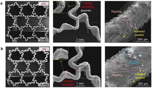
A series of double-asymmetric honeycombs with various wall thickness gradients were designed and successfully prepared by LPBF. No obvious defects like distortion or macroscopic cracks were exhibited in the samples (). It is noteworthy that visible grooves were observed in the LPBF-processed double-asymmetric honeycombs, particularly in the region of overlap boundary. Melt accumulation occurs at the starting of the current melt track, while insufficient liquid occurs at the ending of the formed melt track, resulting in a ‘convex head and concave tail’ phenomenon in the solidified melt track, resulting in grooves at the joint of the two melt tracks. Additionally, the as-built samples displayed particle agglomeration, residual powder adhesion on the gradient honeycomb walls, and a rippling-shaped surface morphology [Citation34]. The inherent thermal effects and residual stresses give rise to slight deviations and distortion within each layer [Citation35], which will affect the laying of the powder bed during the formation of each layer. It is important to note that the manufacturing deficiencies mentioned above may affect the fabricating quality of LPBF-processed double-asymmetric honeycombs to some extent, resulting in amplified local roughness, increased total mass, surface irregularities, and potentially decreased forming accuracy [Citation25, Citation36].
Figure 5. Morphologies of LPBF-processed double-asymmetric honeycombs with the gradation parameter α of (a) 2/3 and (b) 2/5.
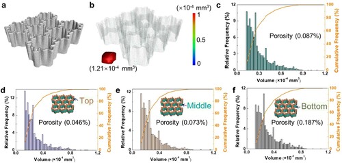
Micro-CT testing was conducted to quantitatively evaluate the distribution of micro-pores and dimensional accuracy in the LPBF-processed double-asymmetric honeycomb with a gradation parameter α of 2/5. The reconstructed model presented in a confirms the successful fabrication of the double-asymmetric honeycomb using LPBF, exhibiting no failures or cracks within the layers. Spherical voids can also be observed from b with the defect volume of 1.21 × 10⁻⁴ mm3. Generally speaking, when the temperature of the molten pool exceeds the boiling point of metallic elements like Ni and Ti [Citation37], bubbles will form inside the molten pool. These bubbles tend to be spherical in shape due to surface tension. If the bubbles fail to escape before the melt solidifies and remain trapped inside the solidified material, pores will be formed. Notably, the statistical result of micro-pores in c shows that most micro-pores are smaller than 0.08 × 10⁻⁴ mm3, resulting in a relative density of 99.91%. Moreover, the observation that the top section of as-built parts exhibited a smaller porosity (0.046%) compared to the middle (0.073%) and bottom sections (0.187%) suggests an improvement in forming quality along the building direction (d–f). As the forming height increases, the thermal accumulation effect during LPBF process intensifies, and the molten pool can maintain a longer liquid time, providing sufficient time for gas escape inside the molten pool, thereby reducing the number of bubbles trapped inside the material after solidification and reducing the porosity of the material [Citation38].
Figure 6. Micro-CT analysis reflecting the pores distribution in the LPBF-processed double-asymmetric honeycomb with the gradation parameter α of 2/5:(a) CT-reconstructed model; (b) distribution of internal defects throughout the structure; Statistical porosity for the (c) whole model, (d) the top, (e) the middle and (f) the bottom sections.
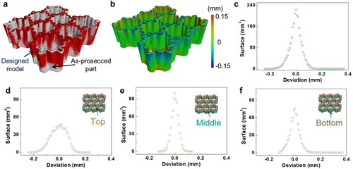
a presented a comparison of overlapping the as-build parts with the designed STL model, b–f show the surface deviation and statistical surface deviation distribution. It was observed that the overall shape and geometry of the as-build parts closely resembled the intended design (a and b), and the deviation of the entire model exhibited a relatively small range from −0.24 mm to 0.368 mm (c). The deviation primarily occurred at the overlap boundary mentioned in , which could be attributed to the energy concentration caused by multiple laser scans at those positions. d–f revealed that the statistical surface deviations of different sections exhibited a Gaussian distribution pattern, all sharing the same peak deviation of 0.0 mm. Furthermore, it is noteworthy that the middle section of the LPBF-processed part exhibited a relatively smaller deviation level, ranging from −0.128 mm to 0.136 mm, compared to the top (−0.24 mm to 0.232 mm) and bottom (−0.12 mm to 0.368 mm) sections. This indicates that the middle section experienced less distortion or deviation during the manufacturing process. On the one hand, the main reason for the size deviation of the top and bottom section during the overall deformation; On the other hand, due to the internal residual stresses induced by cyclic heat during the LPBF processing, micro deformation may occur within the structure, resulting in dimensional deviations.
Figure 7. Micro-CT analysis reflecting the dimensional accuracy of the LPBF-processed double-asymmetric honeycomb with the gradation parameter α of 2/5: (a) Comparison of three-dimensional model; (b) Surface deviation map; statistical surface deviation distribution curve for the (c) whole model, (d) top, (e) middle, and (f) bottom section.
3.3. Mechanical properties of double-asymmetric honeycombs
The stress–strain curves of LPBF-processed double-asymmetric honeycombs also exhibited three stages: pre-collapse, rapid stress decline, and quasi-plateau (a). At the quasi-plateau stage, the stress–strain curves exhibited noticeable undulatory stress growth, with the magnitude increasing with α. The first peak stress and specific compressive strength (SCS) values extracted from the stress–strain curves (a) for the gradient honeycombs with different α are shown in b and c. The results revealed that the first peak stress exhibited a nearly linear increase as the gradation parameter α decreased (b). At the gradation parameter α = 2/3, the double-asymmetric honeycomb obtained a higher specific compressive strength (70.64 MPa·cm3/g) than the asymmetric honeycomb (69.03 MPa·cm3/g). However, as the gradation parameter α decreased further, the specific compressive strength became smaller than that of the asymmetric honeycomb (α = 1, c). From a load-bearing capacity perspective, the double-asymmetric honeycomb with α = 2/3 was advantageous. The specific energy absorption (SEA) versus strain curves demonstrated that the double-asymmetric honeycombs had lower SEA compared to the asymmetric honeycomb in the pre-collapse and rapid stress decline stages, which corresponded to the stress–strain curves (d insert). However, as strain increased further, the double-asymmetric honeycombs exhibited greater SEA advantages over the asymmetric honeycomb, with more significant improvements in SEA at smaller α (d). The SEA values (up to 50% strain) extracted from the SEA-strain curves showed visible enhancement with decreasing α (e). It is important to note that the gradient honeycombs absorbed more energy up to the yield stress compared to the asymmetric honeycomb (f). Furthermore, at the same energy absorption level, the double-asymmetric honeycombs exhibited relatively higher ultimate stresses, implying their suitability for energy absorbers with high allowable stress (f). Comparison of SEA for other energy absorption structures reported in the literature is shown in . Our reported structures display superior SEA and is competitive compared to other energy absorption structures [Citation4, Citation15, Citation17, Citation22, Citation23, Citation39–48].
Figure 8. (a) Stress-strain curves of LPBF-processed double-asymmetric honeycombs, (b) first peak stress and (c) the specific compressive strength (SCS) versus the gradation parameter α; (d) The specific energy absorption (SEA) against the strain, (e) SEA of 50% strain versus α, (f) SEA versus the stress.
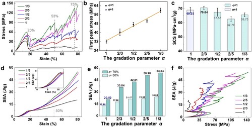
Figure 9. Comparison of specific energy absorption (SEA) for other energy absorption structures [Citation4, Citation15, Citation17, Citation22, Citation23, Citation39–48].
![Figure 9. Comparison of specific energy absorption (SEA) for other energy absorption structures [Citation4, Citation15, Citation17, Citation22, Citation23, Citation39–48].](/cms/asset/d09d8a0d-63e9-4262-9065-26e71f187e44/nvpp_a_2321160_f0009_oc.jpg)
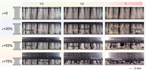
display the compression process at different strains for the double-asymmetric honeycombs. The double-asymmetric honeycombs (α = 1/3 and 1/2) exhibited progressive failure, which was governed by local buckling and folding of the graded walls [Citation23]. It is worth noting that along the building direction, the porosity of the as-built part continuously decreases, which may also be another reason for the progressive failure of asymmetric honeycomb. Specifically, fracture initiated at the thinnest positions on the bottom of the double-asymmetric honeycombs, while the remaining intact structures continued load-bearing as compression progressed. Fracture occurred when the applied stress exceeded the material resistance at the bottom of the remaining intact structures. This progressive failure mechanism, starting from the thinnest position, allowed the double-asymmetric honeycombs to achieve ideal energy absorption characteristics [Citation49], namely the sustained crushing plateau (a). While the asymmetric honeycomb (α = 1) exhibited many cracks resulting from non-uniform buckling deformation during compression. Buckling and tearing of walls led to collapse fracture and loss of structural integrity, ultimately causing a rapid stress decline. The fragmentation and splitting of the asymmetric honeycomb led to the low stress plateau observed during subsequent loading (a). It is evident that the bottom-to-top graded wall thickness of the double-asymmetric honeycombs enabled them to maintain structural stability under compression, while the uniform wall thickness of the asymmetric honeycomb led to catastrophic failure.
Figure 10. Snapshots of the tested LPBF-processed double-asymmetric honeycombs at various compressed strains.
a shows macro images (top view) of the LPBF-processed double-asymmetric honeycombs after compression. For the double-asymmetric honeycomb with α = 1/3, breakage at the bottom was observed, breakage at the bottom was observed, with the majority of the intact honeycomb remaining and numerous small flakes filling the cells. The double-asymmetric honeycomb with α = 2/5 exhibited a mostly intact remaining structure, with some cells on the perimeter being fractured, and a large number of small flakes also detected in the cells. The presence of many small flakes inside the cells indicated high material utilisation rates. At the gradation parameter α = 1/2, extensive damage surfaces and flakes were observed, with only a few intact surfaces remaining. The double-asymmetric honeycomb with a small gradation parameter α = 2/3 and the asymmetric honeycomb (α = 1) fractured completely, resulting in a total loss of integrity after compression, leaving debris pools with large fragments and flakes. Notably, the collapse fracture of the asymmetric honeycomb generated more large fragments compared to the double-asymmetric honeycomb. The analysis above demonstrated that the double-asymmetric honeycombs exhibited higher material utilisation and enhanced energy absorption compared to the asymmetric honeycomb honeycombs.
Figure 11. The macro images in (a) the top view and (b) the side view of the LPBF-processed double-asymmetric honeycombs after compression; (c) XRD patterns of double-asymmetric honeycomb with α of 1/3 under before compression and after compression.
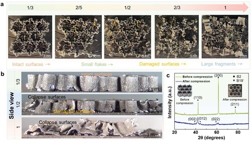
Corresponding to a, the remaining double-asymmetric honeycomb with α = 1/3 retained its structural integrity without detectable longitudinal cracks on the side surfaces (b). Unfortunately, the double-asymmetric honeycomb with α = 1/2 experienced collapse failure of the edge walls and numerous side wall cracks, which were detrimental to the enhancement of load-bearing capacity. Additionally, numerous collapse surfaces from fracture were visible in the side view of the asymmetric honeycomb. This explained the continued increase in load-bearing capacity for the double-asymmetric honeycombs during later stages of compression (a), with more noticeable improvement at lower gradation parameter α, while the load-bearing capacity of the asymmetric honeycomb remained unchanged. XRD patterns revealed the phase constitution before and after compression for the double-asymmetric honeycomb with α = 1/3 (c). In both cases, the three main diffraction peaks (110), (200), and (211) were detected, corresponding to the austenite phase (B2). It was nothing that small peaks (e.g. the (002), (012) and (022)) that indicated the presence of martensite phase (B19′) exhibited in the compressed honeycomb [Citation29]. This suggests that the as-built honeycomb underwent stress-induced martensite transformation during compression. The martensitic transformation likely occurred during the process of wall deformation. Additionally, stress-induced martensitic transformation is known to occur in front of the crack tip before it undergoes plastic deformation [Citation50]. Generally, Young’s modulus of B2 (75–83 GPa) was higher than that of B19′ (28–40 GPa) [Citation51]. Therefore, the fracture events in the structures may occur after stress-induced martensitic transformation [Citation52].
3.4. Superelasticity of double-asymmetric honeycombs
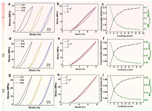
a–d showed the stress–strain curves obtained for the three samples after 9 times cyclic loading-unloading tests above the austenite finish temperature at ∼8% strain. All samples exhibited unclosed stress–strain hysteresis loops during the first two loading and unloading cycles (a, d and g), which can be attributed to increased interface friction and hindered strain recovery caused by internal defects and the rough surface of LPBF-processed parts [Citation53]. It is worth noting that the double-asymmetric honeycombs with smaller gradation parameters exhibited narrower hysteresis loops, indicating lower energy dissipation and more effective interface friction [Citation54]. After three pre-treatments, the relatively closed hysteresis loops of all samples indicated stress-induced transformation from martensite to austenite, allowing for the recovery of residual deformation. However, with each loading cycle, pile-up dislocations acted as stress concentrators, facilitating the initiation and propagation of subsequent micro-cracks or dislocations, leading to a progressive increase in irrecoverable strain with the cycle number. Notably, the irrecoverable strain of LPBF-processed double-asymmetric honeycombs with α values of 1/3, 1/2, and 1 stabilised at approximately 0.28%, 0.36%, and 0.5%, respectively (c, f and i). Furthermore, the dissipated mechanical energy (ME) decreased with an increasing cycle number and a decreasing gradient parameter. A smaller ME indicates less energy loss leading to better heat transfer efficiency, which is beneficial for improving its reversibility to extended numbers of cycles [Citation55].
Figure 12. Cyclic stress-strain curves of LPBF-processed double-asymmetric honeycombs under (a, d, g) the first, second and third pre-treatment, (b, e, and h) and 4th to 9th loading-unloading tests; (c, f, and i) irrecoverable strain and dissipated mechanical energy.
4. Conclusions
This work designed and LPBF-processed a series of double-asymmetric honeycombs, taking inspiration from the triple-junction characteristics and asymmetric walls of cuttlebone, and incorporating a gradient design of wall thicknesses. The mechanical properties of different structural units were studied, the formability, mechanical properties and failure mechanisms of double-asymmetric honeycombs were as clarified, and the superelasticity of double-asymmetric honeycombs was further evaluated. The main conclusions are as follows:
The junction design of the bionic thin-walled structures is beneficial for their load-bearing capacity, it can maintain the integrity of the residual parts after local buckling and failure, and obtain a gradual collapse mode to improve their mechanical performance. The double triple-junction structure possessed has a higher maximum specific compressive strength (9.85 MPa·cm3/g), followed by triple-junction (8.51 MPa·cm3/g) and non-junction (6.82 MPa·cm3/g) structures in order.
The LPBF-processed double-asymmetric honeycombs showed no obvious defects like distortion or macroscopic cracks. The relative density of the LPBF-processed double-asymmetric honeycomb archived 99.91%, with a most micro-pores smaller than 0.08 × 10⁻⁴ mm3 and the statistical surface deviations of different sections exhibited a Gaussian distribution with the peak deviation of 0.0 mm.
The stress–strain curves of the LPBF-processed double-asymmetric honeycombs exhibited three stages: pre-collapse, rapid decline, and quasi-plateau. At gradation parameter α = 2/3, the double-asymmetric honeycomb obtained higher specific compressive strength (70.64 MPa·cm3/g) versus asymmetric honeycomb (69.03 MPa·cm3/g). Graded wall thickness from bottom to top enabled maintaining structural stability under compression, while uniform thickness led to catastrophic failure in asymmetric honeycomb. The XRD patterns revealed that the as-build honeycomb had undergone stress-induced martensite transformation during compression. The double-asymmetric honeycombs with smaller gradation parameter α exhibited narrower hysteresis loops, and the dissipated mechanical energy (ME) decreased with the increasing cycle number and the decreasing gradation parameter α.
Disclosure statement
No potential conflict of interest was reported by the author(s).
Data availability
The data that support the findings of this study are available from the corresponding author upon reasonable request.
Additional information
Funding
References
- Gao JY, Chen S, Ying Liu T, et al. Additive manufacture of low melting point metal porous materials: capabilities, potential applications and challenges. Mater Today. 2021;49:201–230. doi:10.1016/j.mattod.2021.03.019
- Yang J, Gu D, Lin K, et al. Laser additive manufacturing of cellular structure with enhanced compressive performance inspired by Al–Si crystalline microstructure. CIRP J Manuf Sci Technol. 2021;32:26–36. doi:10.1016/j.cirpj.2020.11.003
- Liu H, Gu D, Qi J, et al. Dimensional effect and mechanical performance of node-strengthened hybrid lattice structure fabricated by laser powder bed fusion. Virtual Phys Prototyp. 2023;18(1):e2240306. doi:10.1080/17452759.2023.2240306
- Wei Y, Zhang Y, Song Q, et al. Effects of different configurations and gradients on compression responses of gradient honeycombs via selective laser melting. Thin-Walled Struct. 2022;170:108462. doi:10.1016/j.tws.2021.108462
- Wei K, Chen H, Pei Y, et al. Planar lattices with tailorable coefficient of thermal expansion and high stiffness based on dual-material triangle unit. J Mech Phys Solids. 2016;86:173–191. doi:10.1016/j.jmps.2015.10.004
- Huang W, Zhang Y, Xu Y, et al. Out-of-plane mechanical design of bi-directional hierarchical honeycombs. Compos Part B Eng. 2021;221:109012. doi:10.1016/j.compositesb.2021.109012
- Adams R, Townsend S, Soe S, et al. Mechanical behaviour of additively manufactured elastomeric pre-buckled honeycombs under quasi-static and impact loading. Mater Design. 2022;213:110368. doi:10.1016/j.matdes.2021.110368
- Pehlivan L, Baykasoğlu C. An experimental study on the compressive response of CFRP honeycombs with various cell configurations. Compos Part B Eng. 2019;162:653–661. doi:10.1016/j.compositesb.2019.01.044
- Zhang S, Ma Y, Deng Z. Analytical solution and experimental verification for the buckling failure of additively manufactured octagonal honeycombs. Compos Struct. 2023;303:116306. doi:10.1016/j.compstruct.2022.116306
- Zhang X, Zhang H. Theoretical and numerical investigation on the crush resistance of rhombic and kagome honeycombs. Compos Struct. 2013;96:143–152. doi:10.1016/j.compstruct.2012.09.028
- Simoes M, Harris JA, Ghouse S, et al. Process parameter sensitivity of the energy absorbing properties of additively manufactured metallic cellular materials. Mater Design. 2022;224:111398. doi:10.1016/j.matdes.2022.111398
- Wang K, Chen J, Han Z, et al. Synergistically program thermal expansional and mechanical performances in 3D metamaterials: design-architecture-performance. J Mech Phys Solids. 2022;169:105064. doi:10.1016/j.jmps.2022.105064
- Wei K, Peng Y, Qu Z, et al. A cellular metastructure incorporating coupled negative thermal expansion and negative Poisson’s ratio. Int J Solids Struct. 2018;150:255–267. doi:10.1016/j.ijsolstr.2018.06.018
- Zhang D, Fei Q, Jiang D, et al. Numerical and analytical investigation on crushing of fractal-like honeycombs with self-similar hierarchy. Compos Struct. 2018;192:289–299. doi:10.1016/j.compstruct.2018.02.082
- Li Z, Yao S, Ma W, et al. Energy-absorption characteristics of a circumferentially corrugated square tube with a cosine profile. Thin-Walled Struct. 2019;135:385–399. doi:10.1016/j.tws.2018.11.028
- Yang K, Li Z, Ge D. Quasi-static and dynamic out-of-plane crashworthiness of 3D curved-walled mixed-phase honeycombs. Thin-Walled Struct. 2023;182:110305. doi:10.1016/j.tws.2022.110305
- Hu D, Wang Y, Song B, et al. Energy-absorption characteristics of a bionic honeycomb tubular nested structure inspired by bamboo under axial crushing. Compos Part B Eng. 2019;162:21–32. doi:10.1016/j.compositesb.2018.10.095
- Wu F, Chen Y, Zhao S, et al. Mechanical properties and energy absorption of composite bio-inspired multi-cell tubes. Thin-Walled Struct. 2023;184:110451. doi:10.1016/j.tws.2022.110451
- Yang T, Jia Z, Chen H, et al. Mechanical design of the highly porous cuttlebone: bioceramic hard buoyancy tank for cuttlefish. Proc Natl Acad Sci USA. 2020;117(38):23450–23459. doi:10.1073/pnas.2009531117
- Mao A, Zhao N, Liang Y, et al. Mechanically efficient cellular materials inspired by cuttlebone. Adv Mater. 2021;33:1–8. doi:10.1002/adma.202007348
- Cui CY, Chen L, Feng S, et al. Compressive resistance of the bio-inspired cuttlebone-like sandwich structure under quasi-static load. Int J Mech Sci. 2023;248:108222. doi:10.1016/j.ijmecsci.2023.108222
- Sun G, Xu F, Li G, et al. Crashing analysis and multiobjective optimization for thin-walled structures with functionally graded thickness. Int J Impact Eng. 2014;64:62–74. doi:10.1016/j.ijimpeng.2013.10.004
- Kumar S, Ubaid J, Abishera R, et al. Tunable energy absorption characteristics of architected honeycombs enabled via additive manufacturing. ACS Appl Mater Interfaces. 2019;11(45):42549–42560. doi:10.1021/acsami.9b12880
- Yang J, Gu D, Lin K, et al. Laser 3D printed bio-inspired impact resistant structure: failure mechanism under compressive loading. Virtual Phys Prototyp. 2020;15(1):75–86. doi:10.1080/17452759.2019.1677124
- Yang X, Yang Q, Shi Y, et al. Effect of volume fraction and unit cell size on manufacturability and compressive behaviors of Ni-Ti triply periodic minimal surface lattices. Addit Manuf. 2022;54:102737. doi:10.1016/j.addma.2022.102737
- Chen W, Gu D, Yang J, et al. Compressive mechanical properties and shape memory effect of NiTi gradient lattice structures fabricated by laser powder bed fusion. Int J Extreme Manuf. 2022;4(4):045002. doi:10.1088/2631-7990/ac8ef3
- Yan Z, Zhu J-N, Borisov E, et al. Superelastic response and damping behaviour of additively manufactured nitinol architectured materials. Addit Manuf. 2023;68:103505. doi:10.1016/j.addma.2023.103505
- Denton EJ, Gilpin-Brown JB. The distribution of gas and liquid within the cuttlebone. J Marine Biol Assoc United Kingdom. 1961;41(2):365–381. doi:10.1017/S0025315400023973
- Yuan L, Gu D, Lin K, et al. Electrically actuated shape recovery of NiTi components processed by laser powder bed fusion after regulating the dimensional accuracy and phase transformation behavior. Chin J Mech Eng Addit Manuf Front. 2022;1(4):100056. doi:10.1016/j.cjmeam.2022.100056
- ISO 13314. (2011). Mechanical testing of metals-ductility testing-compression test for porous and cellular metals. International Organization for Standardization 2011. www.iso.org.
- Wang P, Yang F, Zheng B, et al. Breaking the tradeoffs between different mechanical properties in bioinspired hierarchical lattice metamaterials. Adv Funct Mater. 2021; 33(45):2305978. doi:10.1002/adfm.202305978
- Wang P, Yang F, Ru D, et al. Additive-manufactured hierarchical multi-circular lattice structures for energy absorption application. MaterDesign. 2021;210:110116. doi:10.1016/j.matdes.2021.110116
- Wang Y, Liu F, Zhang X, et al. Cell-size graded sandwich enhances additive manufacturing fidelity and energy absorption. Int J Mech Sci. 2021;211:106798. doi:10.1016/j.ijmecsci.2021.106798
- Chmielewska A, Jahadakbar A, Wysocki B, et al. Chemical polishing of additively manufactured, porous, nickel-titanium skeletal fixation plates. 3D Printing Addit Manuf. 2022;9(4):269–277. doi:10.1089/3dp.2020.0209
- Gu D, Yang J, Wang H, et al. Laser powder bed fusion of bio-inspired reticulated shell structure: optimization mechanisms of structure, process, and compressive property. CIRP J Manuf Sci Technol. 2021;35:1–12. doi:10.1016/j.cirpj.2021.04.005
- Yang J, Gu D, Lin K, et al. Laser powder bed fusion of mechanically efficient helicoidal structure inspired by mantis shrimp. Int J Mech Sci. 2022;231:107573. doi:10.1016/j.ijmecsci.2022.107573
- Lu HZ, Ma HW, Luo X, et al. Microstructure, shape memory properties, and in vitro biocompatibility of porous NiTi scaffolds fabricated via selective laser melting. J Mater Res Technol. 2021;15:6797–6812. doi:10.1016/j.jmrt.2021.11.112
- Zaeh MF, Branner G. Investigations on residual stresses and deformations in selective laser melting. Prod Eng. 2010;4(1):35–45. doi:10.1007/s11740-009-0192-y
- Ha NS, Lu G, Xiang X. Energy absorption of a bio-inspired honeycomb sandwich panel. J Mater Sci. 2019;54(8):6286–6300. doi:10.1007/s10853-018-3163-x
- Li W, Li Z, Li S, et al. Crushing behaviors and energy absorption evaluation methods of hexagonal steel tubular columns with triangular cells. Materials (Basel). 2022;15(11):1–15. doi:10.3390/ma15113910
- Liu Y, Qi Y, Sun H, et al. Bionic design of thin-walled tubes inspired by the vascular structure of bamboo. Thin-Walled Struct. 2023;186:110689. doi:10.1016/j.tws.2023.110689
- Niu X, Wang X, Lu Y, et al. Greatly improving the energy absorption capacity of pre-folded tubes via non-uniformizing structures. Acta Mech Sin/Lixue Xuebao. 2023;39(11):423092. doi:10.1007/s10409-023-23092-x
- Tao Y, Li W, Wei K, et al. Mechanical properties and energy absorption of 3D printed square hierarchical honeycombs under in-plane axial compression. Compos Part B Eng. 2019;176:107219. doi:10.1016/j.compositesb.2019.107219
- Voyiadjis GZ, Znemah RA, Wood P. Microstructure and geometry effects on the compressive behavior of LPBF-manufactured inconel 718 honeycomb structures. J Mater Res Technol. 2023;24:1562–1578. doi:10.1016/j.jmrt.2023.03.093
- Wang Z, Zhang J, Li Z, et al. On the crashworthiness of bio-inspired hexagonal prismatic tubes under axial compression. Int J Mech Sci. 2020;186(15):105893. doi:10.1016/j.ijmecsci.2020.105893
- Xiang J, Du J. Energy absorption characteristics of bio-inspired honeycomb structure under axial impact loading. Mater Sci Eng A. 2017;696:283–289. doi:10.1016/j.msea.2017.04.044
- Zhou G, Yu T, Cheng Y, et al. Optimization of printing parameters and out-of-plane compression performance of 316L stainless steel ribbed honeycomb. CIRP J Manuf Sci Technol. 2023;43:71–87. doi:10.1016/j.cirpj.2023.02.004
- Zou M, Xu S, Wei C, et al. A bionic method for the crashworthiness design of thin-walled structures inspired by bamboo. Thin-Walled Struct. 2016;101:222–230. doi:10.1016/j.tws.2015.12.023
- Dong J, Ye G, Wang Y, et al. Design, manufacture and crushing behaviors of buckling-inspired auxetic meta-lattice structures. Int J Smart Nano Mater. 2021;12(4):491–510. doi:10.1080/19475411.2021.1966855
- Yan B, Zhang Y, Jiang S, et al. Mechanical properties and fracture mechanisms of martensitic NiTi shape memory alloy based on various thermomechanical-processing microstructures. J Alloys Compd. 2021;883:160797. doi:10.1016/j.jallcom.2021.160797
- Zhang D, Li Y, Cong W. Multi-scale pseudoelasticity of NiTi alloys fabricated by laser additive manufacturing. Mater Sci Eng A. 2021;821:141600. doi:10.1016/j.msea.2021.141600
- Rauch HA, Cui H, Knight KP, et al. Additive manufacturing of yttrium-stabilized tetragonal zirconia: progressive wall collapse, martensitic transformation, and energy dissipation in micro-honeycombs. Addit Manuf. 2022;52:102692. doi:10.1016/j.addma.2022.102692
- Lu HZ, Chen T, Liu LH, et al. Constructing function domains in NiTi shape memory alloys by additive manufacturing. Virtual Phys Prototyp. 2022;17(3):563–581. doi:10.1080/17452759.2022.2053821
- Chen J, Xing L, Fang G, et al. Improved elastocaloric cooling performance in gradient-structured NiTi alloy processed by localized laser surface annealing. Acta Mater. 2021;208:116741. doi:10.1016/j.actamat.2021.116741
- Hou H, Simsek E, Ma T, et al. Fatigue-resistant high-performance elastocaloric materials made by additive manufacturing. Science. 2019;366(6469):1116–1121. doi:10.1126/science.aax7616