
 ?Mathematical formulae have been encoded as MathML and are displayed in this HTML version using MathJax in order to improve their display. Uncheck the box to turn MathJax off. This feature requires Javascript. Click on a formula to zoom.
ABSTRACT
This study proposes a sandwich structure of triply periodic minimal surface (TPMS) based on the theory of micro-perforated plates. This structure was processed using laser selective melting (SLM) with the acoustic-vibration theoretical model established through the acoustic-electrical analogy method. The theoretical model was verified by comparison with the experimental results, showing that the micro-perforated plate TPMS sandwich structure exhibited good sound absorption performance with the maximum sound absorption coefficients being higher than 0.8. The micro-perforated plate TPMS sandwich resonated when excited by sound waves. The change in the volume fraction affected the size of the cavity volume behind the micro-perforated plate, thereby affecting the resonance frequency. The increase in volume fraction decreased the volume of the cavity behind the structural plate, the sound absorption performance to increase, the resonance frequency to move towards high frequencies, and the sound absorption bandwidth to decrease. The resonance frequency was negatively correlated with the panel thickness. The increase in the panel thickness increased the maximum sound absorption coefficient and decreased the sound absorption bandwidth when the structure resonated. Also, high-order resonance frequencies appeared when the number of cell layers increased to a certain level.
1 Introduction
The sandwich panel structure has lightweight, high-strength mechanical properties and excellent energy absorption capabilities [Citation1–4]. As a composite material, it combines the advantages of different materials and structures with excellent comprehensive performance, and the weight and cost are lower than a single material. Therefore, it has received widespread attention from academia and industry with many researchers beginning to explore and study the acoustic properties of different sandwich structures [Citation5–9]. In recent years, micro-perforated panel structures (MPP) have been used to introduce a sandwich panel structure. The MPP board has micropores of 1 mm or less, and a cavity and a rigid wall behind the board. It is a lightweight and excellent sound-absorbing structure that can achieve high sound impedance and low impedance by relying only on the panel. It is widely used in the fields of rail transportation [Citation10, Citation11], aerospace [Citation12], architecture [Citation13], and underwater acoustics [Citation14], among others. Introducing MPP into the sandwich panel structure to form a new micro-perforated panel sandwich structure (MPPA) can achieve good acoustic performance while meeting the requirements related to mechanical properties [Citation15–21]. The sandwich panel consists of an upper plate, a core material, and a lower plate, among which the core material has a dominant influence on the mechanical properties [Citation22–24]. This has triggered an extensive exploration of sandwich panel structures with various core materials, including a lattice structure, honeycomb structure, foam, and a pyramid structure [Citation25–32].
The TPMS structure has become a good choice for the core material of sandwich structures because of its continuous and smooth structure which can avoid stress concentration. The unique geometric topology and mechanical properties of the TPMS structure [Citation33–36] provide more high-quality options for mechanics, energy absorption, sound absorption, biological scaffolds, and vibration control [Citation37–39]. The TPMS structure as the core material of the sandwich structure, whether it is a homogeneous structure or a gradient structure, provides excellent mechanical properties which are enhanced as the volume fraction becomes larger and has good designability [Citation40]. Some researchers have begun to explore the acoustic performance of TPMS structures. Some studies focus on the sound insulation properties of the structure, while others hope to improve the sound absorption capacity of the structure by designing and modifying some key parameters of the TPMS structure [Citation41–44].
As a typical additive manufacturing technology, the SLM process uses a laser beam as a heat source and scans the metal powder bed layer by layer according to the planned path in the three-dimensional slice model. The scanned metal powder quickly melts and solidifies with the layers accumulating to form parts, which overcomes the difficulty of processing high-precision micropores with traditional technology [Citation45, Citation46] and provides an effective means for the precise design of micro-perforated plate TPMS sandwich structures. The TPMS sandwich structure based on SLM processing has the processing advantage of one-piece moulding, and its function-based generation feature provides it with excellent design ability.
This paper combines the TPMS structure with the micro-perforated plate sandwich structure and proposes a new micro-perforated plate TPMS sandwich structure. Based on the excellent mechanical properties of the TPMS sandwich structure, the sound absorption performance of the new structure is expanded, providing more choices for the engineering application of the TPMS sandwich. The theoretical model of the acoustic vibration of the micro-perforated plate TPMS sandwich structure was established using an analogy method. The effects of volume fraction, panel thickness and cell layer number on the sound absorption performance of the micro-perforated plate TPMS sandwich structure were analysed and discussed.
2 Model and experimental design
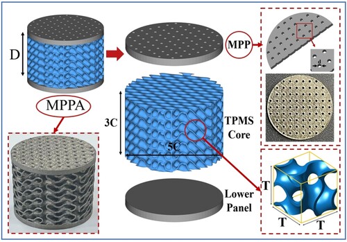
This article proposes a new micro-perforated plate TPMS sandwich structure as shown in .
Figure 1. Schematic representation and sample of micro-perforated plate TPMS sandwich structure design.
2.1. Acoustic-vibration theoretical model of micro-perforated plate TPMS sandwich structure
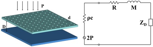
The micro-perforated plate contains many evenly distributed small holes of a certain thickness which form many parallel Helmholtz resonators with the space behind the plate. These parallel Helmholtz resonators are the basic resonance units of the micro-perforated plate structure. According to the acoustic-electrical analogy method (the corresponding schematic representation is shown in .), the acoustic impedance rate of the microporous structure is as follows [Citation47]:
(1)
(1) In the formula,
indicates the viscosity coefficient of air,
represents the plate thickness and the length of the hole,
denotes the perforation diameter,
refers to the air density,
indicates the imaginary unit,
is the angular frequency of the sound wave,
, the unit is kHz, and
denotes the punching constant.
Figure 2. Acoustic-electrical analogy diagram (Acoustic resistance plays a similar role to resistance and can represent the loss of energy in the system; sound quality
is similar to inductance, reflecting the inertia of the system; acoustic impedance rate
is the same as capacitance, reflecting the system’s ability to store capacity; sound pressure
like the power supply electromotive force, it is the external factor that causes the system to move;
represents the air load impedance when the sound wave radiates outward.)
The relative acoustic impedance of micropores is as follows [Citation47]:
(2)
(2) where
indicates the acoustic resistance and
denotes the acoustic impedance. The expressions of
and
are as follows [Citation47]:
(3)
(3)
(4)
(4)
(5)
(5)
(6)
(6)
(7)
(7)
Among them, indicates the opening ratio, which is the ratio of the opening area to the panel area per unit area.
The classic micro-perforated plate theory is applicable when the back cavity is an air layer, and the internal volume of the TPMS sandwich structure cannot be ignored, so the height of the cavity layer behind the plate had to be corrected as follows:
(8)
(8) where
indicates the period size of the TPMS sandwich structure,
denotes the volume size of the unit cell of the TPMS sandwich structure, and n represents the number of cell layers.
2.2. Micro-perforated plate TPMS sandwich structure design
The TPMS sandwich The TPMS sandwich consists of an upper plate, a core material, and a lower plate with the TPMS core material being the main factor that determines the performance of the sandwich structure. TPMS is a three-dimensional orthogonal surface with zero average curvature and periodicity. The expression in the Cartesian coordinate system is as follows [Citation48]:
(9)
(9) The modelling method based on the triply periodic minimal surface expresses the structural characteristics between cells through concise functional expressions. The general expression of TPMS is as follows [Citation48]:
(10)
(10)
EquationEquation (10)(10)
(10) expresses the surface through an implicit function and the values of each point are constant so the surface is also called an isosurface.
represents the amplitude of the function,
affects the period of the function,
denotes the phase translation of the function, and the function value
controls the offset of the surface. When
, the surface defined by the implicit function divides the space into two parts with equal volumes, and the volume fraction of the formed porous structure is 50%. For the TPMS modelling method, different periodic surface equations can generate structures of different unit types. Currently, the existing TPMS structures include spiral gyroid, diamond surface, primitive surface, and I-WP surface. According to the research of Diab [Citation39], the sound absorption capacity of the gyroid structure is relatively excellent among the many TPMS structures. The gyroid structure is divided into a skeleton gyroid structure and a lamellar gyroid structure which has relatively excellent mechanical properties. As the volume fraction of the lamellar gyroid structure increases, mechanical properties such as elastic modulus and yield strength increase accordingly [Citation40]. This study aimed to expand the sound absorption performance of the new structure based on the excellent mechanical properties of the TPMS sandwich structure, so the lamellar gyroid structure with better mechanical properties was selected as the core material.
The surface angle of the gyroid structure was approximately 38°, and it was a body-centred cubic structure. This surface divided the space of the unit into two parts, and the extension direction spiralled upward, so it is a spiral icosahedron. The basic equation of the gyroid structural surface is as follows [Citation48]:
(11)
(11) EquationEquation (11)
(11)
(11) indicates that the gyroid surface has obvious periodicity in the three directions of
,
, and
, and the periods are the same. When
, the surface is minimal. The minimal surface at this time is an entity, which divides the space into two parts, entity and void, that is,
and
; when
is small, the porosity gradually decreases and the surface becomes cross-linked; when
is greater than a certain level, the porosity increases, causing a discontinuity in the surface. The basic equations of the surface are often optimised to better control the shape of the gyroid structure and avoid surface discontinuity. The adjustable TPMS implicit function equation in this study was approximated as follows:
(12)
(12) Here,
,
, and
control the unit size of the unit in the
,
, and
directions, the period
,
controls the shape change of the unit, and
denotes the relative density control parameter. If
is defined as the solid part and
is the pore part, then the triple integral of
represents the volume of the solid part and the volume fraction
of the gyroid structure can be expressed as follows:
(13)
(13)
(14)
(14) where
represents the three-dimensional spatial change area of the gyroid structure. For a uniform periodic structure, the
range is
and the unit porosity
is defined as follows:
(15)
(15)
(16)
(16)
In the formula, denotes the total volume of the unit and
represents the volume composed of the unit. Different
and
values have a linear relationship in theory, and different
values correspond to different
values. The relationship between the
value and the relative density can be approximated by fitting the curve as follows:
(17)
(17) This linear relationship applies to the range of relative density from 0–50%. The significance of obtaining the linear relationship between the
value and the relative density is that the relative density (porosity) of the porous structure can be obtained by adjusting the value of the control parameter. The three-period minimal surface established using the implicit function method is an unclosed isosurface. It is necessary to add isosurfaces, that is, a subroutine to generate a surface model using the Magics commercial software to establish equivalent positions, etc.; the solid cell generated after closing the surface model is called a skeleton cell. Next, the isosurface is offset by a certain distance and the solid cell generated after closing the end face is called a lamellar cell. The subsequent text uses sheet-like cells which are arrayed, that is, the TPMS core material design is completed.
The position of the micropores on the upper panel of the lamellar TPMS sandwich was consistent with the offset of the TPMS curved surface, that is, each micro-hole on the microperforated plate corresponded to each cavity of the TPMS structure, the micropores were all 1 mm and the micropore spacing was half the unit cell size. As shown in , the micropores formed using the SLM technology were uniform, the board surface was smooth, and the moulding quality was good. Each micropore was located at the centre of the aperture of the TPMS sandwich and was evenly distributed with the surrounding cavities. As the volume fraction of the TPMS sandwich increased, the micropores and the structural apertures gradually became inscribed. At the opening of the micro-perforated plate, the porosity was the total open area divided by the panel surface area. Through Boolean calculation, the core structure was designed with two panels on the top and bottom and SLM technology was used to form the sandwich structure.
2.3. Materials and experimental methods
2.3.1. Experimental materials
Ti6Al4V is a commonly used titanium alloy and was selected for use in this study. The chemical element composition of the powder is shown in and the SEM image of the aerosolized Ti6Al4V powder is shown in . Fewer small particles on the surface of the metal powder, the better the fluidity, thereby providing better moulding quality. Typically, particle sizes between D10 and D90 (10–90 μm) are used in the SLM process. The particle size also affects the density of the moulded parts. The average particle size of the Ti6Al4V powder in this experiment was approximately 30–50 μm, which was relatively high but with a narrow distribution range. All specimens were prepared using EPLUS-150 produced by Beijing E Plus 3d Tech. Co., Ltd. The moulded specimen in shows that all the sandwich structures had good moulding quality and there was no serious powder-sticking.
Figure 3. The SEM image of Ti6Al4V powder.
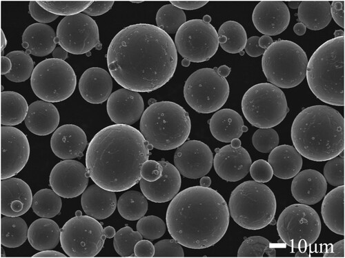
Table 1. Mass fractions of different elements in Ti6Al4V powder.
2.3.2. Acoustic impedance tube experimental measurement
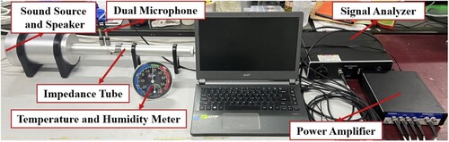
The measurement of the sound absorption coefficient of the TPMS sandwich was conducted according to the International Organisation for Standardisation standard ISO 10534-2:1998 (E) ‘Measurement of sound absorption coefficient and acoustic impedance in acoustic impedance tubes Part 2: Transfer function’. The impedance tube model was BSWA SW4201, with an inner diameter of 29 mm and a measurement frequency range of 450–6400 Hz. The test equipment and the principle are shown in .
Figure 4. Experimental equipment diagram.
The comparison between the test results and the theoretical model in shows that when combined with the micro-perforated plate theory and correcting the back cavity depth, the theoretical value of the frequency of the micro-perforated plate TPMS sandwich resonates consistently with the experimental value. The experimental value is higher than the theoretical value and the distinction near the peak is smaller than other frequencies because the theory assumes that the surface of the microperforated plate is smooth but it is relatively rough in practice. The friction within the micropores increases when stimulated by sound waves, thereby increasing the friction loss and enhancing the sound absorption effect. When the micro-perforated plate TPMS sandwich is located in a frequency range where the sound absorption ability is low, this effect becomes more obvious, resulting in a relatively large error in the theoretical and experimental results. Also, the sound absorption gets closer and closer at the peak as the sound absorption capacity becomes the main factor affecting the structure’s sound absorption coefficient. shows the design parameters of the micro-perforated plate TPMS sandwich structure.
Figure 5. Comparison chart between test results and theoretical model.
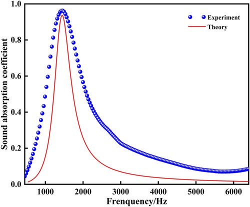
Table 2. Various parameters of micro-perforated plate TPMS sandwich structure sample.
3 Results and discussion
Changes in the volume fraction, panel thickness, cell layer number, and structure of the TPMS sandwich structure affected its sound absorption performance. The TPMS sandwich with micro-perforated plates was more affected by changes in the structural parameters, therefore, this study explored the effects of micro-perforated plates on the structure. The impact of different volume fractions, panel thicknesses, and cell layer numbers on the sound absorption performance of the micro-perforated TPMS sandwich structure was analysed when the hole diameter and the number of positions of the perforated plate were constant (micro-hole diameter: 1 mm).
The aperture size and the opening rate of the perforated panels were key factors that affected the sound absorption performance of the TPMS sandwich. The frequency at which the micro-perforated plate resonated under the action of sound waves is called the resonance frequency which is expressed as follows [Citation30]:
(18)
(18) In the formula,
indicates the cross-sectional area of the micropore,
, which represents the product of the cavity volume and the height of the micropore. The resonance frequency of the micro-perforated plate TPMS sandwich under the action of incident sound waves is related to the size of the micropores and the cavity. Attention is usually paid to the peak value and bandwidth of the sound absorption coefficient curve when characterising the sound absorption performance. The sound absorption broadband is the difference between the two corresponding frequencies where the energy absorption coefficient drops by half from the peak value of the sound absorption characteristic curve. At the same time, the position of the frequency band is also very important. The sound absorption coefficient at too high a frequency has little engineering significance, so this article only evaluates the sound absorption curve from 0 to 6500 Hz. When the sound absorption coefficient is lower than 0.2, it is considered to have no sound absorption performance.
3.1. Analysis of the influence of volume fraction on sound absorption performance
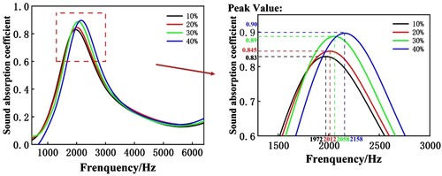
When the micropore size of the microperforated plate is constant, the size of the cavity volume behind the plate affected the resonance frequency because of the change in the volume fraction. At the same time, the pore size and mass of the TPMS core porous structure also changed with the volume fraction. These corresponding changes also affect its sound absorption performance. shows the excellent sound absorption performance of the micro-perforated plate lamellar TPMS sandwich under different volume fraction conditions. When the volume fraction was 10%, the maximum sound absorption coefficient of the structure was 0.83, the maximum frequency when resonance occurred was 1972Hz, and the sound absorption bandwidth was 6 1/3 octaves. As the volume fraction increases, the sound absorption coefficient and maximum resonance frequency also gradually increase. The bandwidth was 6 1/3 octaves. The increase in the volume fraction affected the size of the cavity behind the micro-perforated plate, that is, the larger the volume fraction was, the smaller the volume of the cavity, and the resonant frequency increased and moved towards a relatively high frequency. Therefore, as the volume fraction increases, the sound absorption performance of the micro-perforated plate TPMS sandwich increases and the resonant frequency gradually increases as the volume of the air cavity decreases. The sound absorption bandwidth of the micro-perforated plate-type lamellar TPMS sandwich structure was 6 1/3 octaves.
Figure 6. Sound absorption curves and peak diagrams of different volume fractions.
3.2. Analysis of the influence of panel thickness on sound absorption performance
EquationEquation (18)(18)
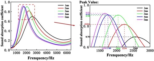
(18) shows that the depth of micropores also affects the sound absorption performance. The thickness of the upper panel is the depth of micropores of the micro-perforated plate TPMS sandwich and increasing the thickness of the panel will also increase the mass and the stiffness of the structure. The influence of the panel thickness on the sound absorption performance of the micro-perforated plate lamellar TPMS sandwich structure is shown in . When the upper wall thickness was 1 mm, the maximum sound absorption coefficient of the structure was 0.70, and the maximum resonance frequency was 2560 Hz. As the thickness of the panel increases, the maximum absorption coefficient gradually becomes larger, the maximum resonance frequency gradually and the sound absorption bandwidth decreases.
Figure 7. Sound absorption curves and peak diagrams of different panel thicknesses.
3.3. Analysis of the influence of the number of cell layers on sound absorption performance
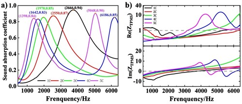
The change in the number of cell layers affects the size of the cavity behind the plate and, therefore the sound absorption performance of the micro-perforated plate-type TPMS sandwich. (a) shows the effect of the number of cell layers on the sound absorption performance of the microperforated plate lamellar TPMS sandwich structure. When the panel thickness and volume fraction were constant, and the number of cell layers increased from 1C to 5C, the first-order resonance frequency of the structure and the corresponding sound absorption bandwidth gradually decreased. Note that when the number of cell layers increased and the sound absorption coefficient reached 4C and 5C, a second higher resonance peak appeared because the propagation path of sound was extended causing the sound to dissipate more energy through the cavity, and the characteristic impedance of the structure gradually increased. (b) presents the changes in the real and imaginary parts of the acoustic impedance, showing that at high frequencies, the real part of the acoustic impedance of the structures with 4C and 5C becomes larger and the imaginary part becomes smaller. The real part of acoustic impedance represents acoustic resistance, which is the ability of sound to propagate and radiate energy to the medium, while the imaginary part represents acoustic impedance, whose energy is stored in the near field of the wave field and is not radiated. Therefore, the energy radiated and dissipated by the sound increases so a second peak appears.
Figure 8. (a) Sound absorption curves and peak marks for different panel thicknesses; (b) Real and imaginary parts of acoustic impedance.
4. Conclusions
This paper proposed a new micro-perforated plate sandwich structure based on the TPMS. The sound absorption theoretical model of the micro-perforated plate TPMS sandwich was established using the acoustic-electrical analogy theory and verified experimentally. The factors affecting the sound absorption performance of the micro-perforated plate TPMS sandwich were studied demonstrating that it had good sound absorption performance. The conclusions are as follows:
The upper panel of the micro-perforated plate TPMS sandwich had a uniform number of micropores with consistent hole diameters, giving excellent sound absorption performance: the sound absorption coefficient of the structure was greater than 0.5 at 900 Hz and the maximum sound absorption coefficient was greater than 0.8.
The micro-perforated plate TPMS sandwich resonated when excited by sound waves. The change in volume fraction affected the size of the cavity volume behind the micro-perforated plate, thereby affecting the resonant frequency. The pore size and mass also changed with the volume fraction, affecting the sound absorption performance. The increase in volume fraction decreased the cavity volume behind the micro-perforated plate-type TPMS sandwich and increased the sound absorption performance and the resonance frequency, the frequency direction moved, and the sound absorption bandwidth decreased.
The resonance frequency of the micro-perforated plate-type TPMS sandwich structure was negatively correlated with the panel thickness. The panel thickness determined the depth of the micropores. The increase in panel thickness increased the maximum sound absorption coefficient and decreased the sound absorption bandwidth when the structure resonated, which was opposite to the effect of the changes in the volume fraction on the resonance frequency but consistent with the effect presented by the resonance frequency theory.
The change in the number of cell layers affected the cavity volume behind the micro-perforated plate, thereby affecting the resonant frequency. The increase in the number of cell layers increased the characteristic impedance and changed the corresponding ratio of real and imaginary energy consumption. When the number of cell layers was 4C and 5C, a higher second-order resonance peak appeared.
CRediT authorship contribution statement
Zhonghua Li: Methodology, Investigation, Validation, Visualization, Writing– original draft, Writing– review & editing. Yujun Zhou: Methodology, Investigation, Software, Validation, Visualization, Writing– original draft, Writing– review & editing. Xiangnan Kong: Writing– original draft, Validation, Resources, Writing– review & editing. Pengfei Zhang: Validation, Resources, Writing– review & editing. Sichen Pei: Validation, Resources, Writing– review & editing. Lipeng Ge: Validation, Resources, Writing– review & editing. Yunfei Nie: Validation, Resources, Writing– review & editing. Bin Liu: Validation, Resources, Writing– review & editing.
Disclosure statement
No potential conflict of interest was reported by the author(s).
Data availability
All relevant data for reproducing the calculations are given in the main publication text.
Additional information
Funding
References
- Ramnath BV, Alagarraja K, Elanchezhian C. Review on sandwich composite and their applications [J]. Mater Today Proc. 2019;16:859–864.
- Birman V, Kardomateas G A. Review of current trends in research and applications of sandwich structures [J]. Compos B Eng. 2018;142:221–240.
- D'alessandro V, Petrone G, Franco F, et al. A review of the vibroacoustics of sandwich panels: models and experiments [J]. J Sandw Struct Mater. 2013;15(5):541–582.
- Patekar V, Kale K. State of the art review on mechanical properties of sandwich composite structures [J]. Polym Compos. 2022;43(9):5820–5830.
- Asadi Jafari MH, Zarastvand M, Zhou J. Doubly curved truss core composite shell system for broadband diffuse acoustic insulation [J]. J Vib Control. 2023: 10775463231206229.
- Ghafouri M, Ghassabi M, Zarastvand M R, et al. Sound propagation of three-dimensional sandwich panels: influence of three-dimensional re-entrant auxetic core [J]. AIAA J. 2022;60(11):6374–6384.
- Zarastvand M, Asadijafari M, Talebitooti R. Acoustic wave transmission characteristics of stiffened composite shell systems with double curvature [J]. Compos Struct. 2022;292:115688.
- Zarastvand M, Ghassabi M, Talebitooti R. A review approach for sound propagation prediction of plate constructions [J]. Arch Comput Methods Eng. 2021;28:2817–2843.
- Zarastvand M, Ghassabi M, Talebitooti R. Prediction of acoustic wave transmission features of the multilayered plate constructions: A review [J]. J Sandw Struct Mater. 2022;24(1):218–293.
- Lee W-Y, Kim J-C, Noh H-M. Application of a micro-perforated panel absorber to reduce the curve squeal noise of railways [J]. Noise Control Eng J. 2021;69(6):507–517.
- Czwielong F, Floss S, Kaltenbacher M, et al. Influence of a micro-perforated duct absorber on sound emission and performance of axial fans [J]. Appl Acoust. 2021;174:107746.
- Qian Y, Wei Y, Kong D, et al. Experimental investigation on motor noise reduction of unmanned aerial vehicles [J]. Appl Acoust. 2021;176:107873.
- Hoshi K, Hanyu T, Okuzono T, et al. Implementation experiment of a honeycomb-backed MPP sound absorber in a meeting room [J]. Appl Acoust. 2020;157:107000.
- Hou J, Zhu H, Yuan S, et al. Sound transmission characteristics of underwater flexible micro-perforated panels [J]. Appl Acoust. 2021;181:108165.
- Meng H, Galland M-A, Ichchou M, et al. On the low frequency acoustic properties of novel multifunctional honeycomb sandwich panels with micro-perforated faceplates [J]. Appl Acoust. 2019;152:31–40.
- Tang Y, Ren S, Meng H, et al. Hybrid acoustic metamaterial as super absorber for broadband low-frequency sound [J]. Sci Rep. 2017;7(1):43340.
- Yu D, Wang X, Mei Y. A design method for labyrinth sound absorption structure with micro-perforated plates. Proceedings of the journal of physics: conference series, F, 2020 [C]. IOP publishing.
- Meng H, Galland M-A, Ichchou M, et al. Small perforations in corrugated sandwich panel significantly enhance low frequency sound absorption and transmission loss [J]. Compos Struct. 2017;182:1–11.
- Jiang C, Li X, Xiao W, et al. Acoustic characteristics of microperforated plate with variable cross-sectional holes [J]. J Acoust Soc Am. 2021;150(3):1652–1662.
- Xu Z, He W, Peng X, et al. Sound absorption theory for micro-perforated panel with petal-shaped perforations [J]. J Acoust Soc Am. 2020;148(1):18–24.
- Wong Y-S, Sekar V, Noum SYE, et al. Effect of thickness and perforation size on the acoustic absorption performance of a micro-perforated panel. Proceedings of the MATEC Web of conferences, F, 2021 [C]. EDP sciences.
- Styles M, Compston P, Kalyanasundaram S. The effect of core thickness on the flexural behaviour of aluminium foam sandwich structures [J]. Compos Struct. 2007;80(4):532–538.
- Alphonse M, Raja V B, Krishna V G, et al. Mechanical behavior of sandwich structures with varying core material–A review [J]. Mater Today Proc. 2021;44:3751–3759.
- Tiwari G, Khaire N. Ballistic performance and energy dissipation characteristics of cylindrical honeycomb sandwich structure [J]. Int J Impact Eng. 2022;160:104065.
- Yoon S, Schiffer A, Cantwell W J, et al. Detection of core-skin disbonds in honeycomb composite sandwich structures using highly nonlinear solitary waves [J]. Compos Struct. 2021;256:113071.
- Xu J, Gao L, Xiao M, et al. Isogeometric topology optimization for rational design of ultra-lightweight architected materials [J]. Int J Mech Sci. 2020;166:105103.
- Ye G, Bi H, Li Z, et al. Compression performances and failure modes of 3D printed pyramidal lattice truss composite structures [J]. Compos Commun. 2021;24:100615.
- Khan N, Chakraborty P. Thermomechanical homogenization of corrugated core sandwich structures of reusable launch vehicles [J]. AIAA J. 2021;59(10):4228–4242.
- Liu J, Ou H, He J, et al. Topological design of a lightweight sandwich aircraft spoiler [J]. Materials (Basel). 2019;12(19):3225.
- Wang D-W, Wen Z-H, Glorieux C, et al. Sound absorption of face-centered cubic sandwich structure with micro-perforations [J]. Mater Des. 2020;186:108344.
- Wang B, Wu L, Ma L, et al. Mechanical behavior of the sandwich structures with carbon fiber-reinforced pyramidal lattice truss core [J]. Mater Des. 2010;31(5):2659–2663.
- Zhang K, Zeng T, Xu G, et al. Mechanical properties of SiCp/SiC composite lattice core sandwich panels fabricated by 3D printing combined with precursor impregnation and pyrolysis [J]. Compos Struct. 2020;240:112060.
- Sharma D, Hiremath S S. Additively manufactured mechanical metamaterials based on triply periodic minimal surfaces: performance,: challenges, and application [J]. Mech Adv Mater Struct. 2022;29(26):5077–5107.
- Almahri S, Santiago R, Lee D-W, et al. Evaluation of the dynamic response of triply periodic minimal surfaces subjected to high strain-rate compression [J]. Addit Manuf. 2021;46:102220.
- Tran P, Peng C. Triply periodic minimal surfaces sandwich structures subjected to shock impact [J]. J Sandw Struct Mater. 2021;23(6):2146–2175.
- Poltue T, Karuna C, Khrueaduangkham S, et al. Design exploration of 3D-printed triply periodic minimal surface scaffolds for bone implants [J]. Int J Mech Sci. 2021;211:106762.
- Li W, Yu G, Yu Z. Bioinspired heat exchangers based on triply periodic minimal surfaces for supercritical CO2 cycles [J]. Appl Therm Eng. 2020;179:115686.
- Zhao M, Liu F, Fu G, et al. Improved mechanical properties and energy absorption of BCC lattice structures with triply periodic minimal surfaces fabricated by SLM [J]. Materials (Basel). 2018;11(12):2411.
- Abueidda D W, Jasiuk I, Sobh N A. Acoustic band gaps and elastic stiffness of PMMA cellular solids based on triply periodic minimal surfaces [J]. Mater Des. 2018;145:20–27.
- Zhang C, Zheng H, Yang L, et al. Mechanical responses of sheet-based gyroid-type triply periodic minimal surface lattice structures fabricated using selective laser melting [J]. Mater Des. 2022;214:110407.
- Xiang-Nan K, Bin L, Zhong-Hua L, et al. Research on sound absorption properties of tri-periodic minimal surface sandwich structure of selective laser melting titanium alloy [J]. Mater Trans. 2023;64(4):861–868.
- Yang W, An J, Chua C K, et al. Acoustic absorptions of multifunctional polymeric cellular structures based on triply periodic minimal surfaces fabricated by stereolithography [J]. Virtual Phys Prototyp. 2020;15(2):242–249.
- Zhang M, Liu C, Deng M, et al. Graded minimal surface structures with high specific strength for broadband sound absorption produced by laser powder bed fusion [J]. Coatings. 2023;13(11):1950.
- Zhang P, Li Z, Liu B, et al. Sound absorption performance of micro-perforated plate sandwich structure based on triply periodic minimal surface [J]. J Mater Res Technol. 2023;27:386–400.
- Liu Z, Zhan J, Fard M, et al. Acoustic properties of multilayer sound absorbers with a 3D printed micro-perforated panel [J]. Appl Acoust. 2017;121:25–32.
- Arjunan A, Baroutaji A, Latif A. Acoustic behaviour of 3D printed titanium perforated panels. Results Eng. 2021;11:100252), [Z]. 2021.
- Maa D-Y. Potential of microperforated panel absorber [J]. J Acoust Soc Am. 1998;104(5):2861–2866.
- Feng J, Fu J, Yao X, et al. Triply periodic minimal surface (TPMS) porous structures: from multi-scale design, precise additive manufacturing to multidisciplinary applications [J]. Int J Extreme Manuf. 2022;4(2):022001.