
 ?Mathematical formulae have been encoded as MathML and are displayed in this HTML version using MathJax in order to improve their display. Uncheck the box to turn MathJax off. This feature requires Javascript. Click on a formula to zoom.
ABSTRACT
Material Extrusion (MEX) Additive Manufacturing (AM) has risen as a promising technology to monolithically manufacture smart structures with embedded sensors. Despite all the benefits of MEX AM, 3D printed piezoresistive sensors still suffer from low sensitivity, making them unsuitable for the detection of low values of force, displacement and bending angle. In the present paper, a simple, effective, and inexpensive method to increase the sensitivity in 3D printed sensors is proposed, based on the leveraging of the ironing strategy, which resulted in an improvement in the sensitivity of 83% compared to traditional process parameter selection. The ironing strategy reduced intralayer porosity by 59%, as verified by X-Ray CT. Additionally, the ironing strategy involves an increased healing time, which promotes the polymer chain diffusion between layers, which translated into a greater stability of the sensor when cyclically stressed. Smart structures capable of detecting small forces (0.19 N of resolution against 1.96 N for traditional MEX scenario) and smart auxetic devices have been manufactured, demonstrating the potential of the proposed approach. The present research demonstrates the ability to reduce interlayer voids by using an intrinsic feature of the MEX process and consequently improve electrical performance of 3D printed sensors.
Highlights
Usage of the ironing strategy to enhance the sensitivity of 83% in 3D printed sensors
Direct correlation between increased sensitivity and reduced porosity due to the ironing strategy
X-Ray CT scan was used to analyse the void volume fraction: reduction of 59% when performing ironing
Fabrication of smart structures capable of detecting low values of force
1. Introduction
Material Extrusion (MEX), one of the most popular Additive Manufacturing (AM) technologies, offers the manufacturing flexibility to jointly extrude multiple materials in the same fabrication time, resulting in simple manufacturing strategies for assembly-free, multi-material structures [Citation1,Citation2]. The increased interest in multi-material structures has motivated researchers to study new methods to improve the adhesion between different materials extruded in the same manufacturing cycle, such as process parameters, post-processing, mechanical interlocking and printing strategies [Citation3–8]. Recently, the multi-nozzle extrusion has been used to create assembly-free structures with embedded sensors capable of detecting various kinds of external stimuli such as bending, contact force and/or deformation [Citation9]; demonstrating the extremely advantageous possibility to jointly extrude electrically conductive materials and extremely soft material for wearable electronics [Citation10]. Despite recent advances in the fabrication of piezoelectric [Citation11,Citation12] and capacitive sensors [Citation13–15] manufactured via the MEX technique, MEX piezoresistive sensors continue to have the potential to impact the sensor community at large due to (i) the possibility to sense multiple variables (i.e. force, strain, bending, torque and so on) and (ii) the possibility to be embedded inside thermoplastic-based components with ease [Citation16–18].
Piezoresistive sensors operate based on the change of electrical resistance when deformed and are typically manufactured by either employing commercial or custom-made conductive materials composed of a thermoplastic matrix doped with conductive fillers (i.e. carbon black, carbon nanotubes, etc.) [Citation19–25]. The multi-material MEX approach has been used to fabricate several robotic systems capable of detecting multiple stimuli. Wang et al. [Citation26] fabricated a foldable magnetic soft robot with an embedded piezoresistive sensor in a single manufacturing process, capable of changing electrical resistance every time the robot was folded. Other works have developed 3D printed gripper systems with embedded sensors [Citation21,Citation27]. Stano et al. fabricated a polycaprolactone (PCL)-based finger with an embedded strain sensor capable of detecting the position in the x-y space [Citation28]. Singh et al. [Citation29] fabricated a bellow with a piezoresistive ring-shaped sensor providing displacement feedback through a change in its electrical resistance. Matharu et al [Citation30] employed 3D printed piezoresistive flexible sensors to obtain feedback from a jellyfish-like soft robot while swimming.
Piezoresistive sensors have been studied as a means to bridge the gap with other sensors manufactured with traditional technologies in terms of performance. Maurizi et al. experimentally validated a quasi-static model to calibrate 3D printed piezoresistive sensors integrated inside polylactic acid (PLA) structures [Citation31]. Arh et al. [Citation32] used the Bridgman model to determine the dynamic piezoresistivity coefficients in different orientations, allowing future modelling regardless of the orientation of the embedded sensor inside the dielectric structure.
3D printed piezoresistive sensors capable of detecting bending angle are extremely attractive and have risen as one of the most promising application points for multi-material MEX. Such sensors have been embedded inside (i) soft structures used as grippers to manipulate fragile objects, (ii) rehabilitative and wearable devices [Citation33–38]. Despite all the aforementioned benefits, piezoresistive sensors prepared via MEX technique still suffer of poor sensitivity and conductivity. At the state of the art, three main strategies have been employed to address such problem. The first strategy relies on the sensor geometry optimisation: as shown in [Citation39–41] the sensor design can be actively use to improve the sensor sensitivity by concentrating the bending in small sections. The second way to improve the sensitivity in 3D printed piezoresistive sensors is based on the material modification: the creation of three dimensional conductive networks inside the thermoplastic matrix [Citation42] and the usage of different conductive fillers such as graphene nanoplatelets and silver nanoparticles [Citation43] has been proven to greatly increase sensor sensitivity. The third method to improve the sensitivity of 3D printed piezoresistive sensor is based on the optimisation of printing process parameters [Citation44,Citation45]: Palmic et al [Citation46] demonstrated that the conductivity can be improved by setting a layer height value ranging between 0.15 and 0.3 mm. Goh et al [Citation47] demonstrated the direct correlation between infill type and sensitivity of piezoresistive sensors. Their work found that a deposition direction of 45, and 0° provided the best results in terms of sensitivity. All of the methods found in literature do not take into account the layer adhesion and porosity issues that negatively affect sensors produced via MEX, and mainly focus on the chemical aspect of the raw material being processed, as well as optimisation of design and process parameters.
In the present paper, the authors addressed the problem of poor electrical performance in 3D printed piezoresistive sensors by using a novel approach based on the improvement of the layer-by-layer adhesion, proving that a strong correlation between sensor sensitivity and interlayer voids occurs. The ironing strategy which results to be an extremely effective, simple and inexpensive method was employed to successfully improve the sensitivity in 3D printed piezoresistive sensors: such strategy can also be potentially used in conjunction with the three aforementioned methods widely exploited in scientific literature. This strategy, still underexploited, makes the conductive tracks compact via the application of heat and pressure with the hot-end, which increased the sensitivity by 82.7%. The findings at the macro scale have been correlated to the internal microstructure of the sensor by employing an X-Ray Computed Tomography (CT) system, discovering a porosity reduction of 59.4%. This simple technique can be leveraged to fabricate smart structures with enhanced performance to detect small changes in force, bending and displacement. The adhesion-centered approach, based on the reduction of voids by means of mechanical pressure, presented in the present research could be potentially used also in conjunction with traditional methods to enhance sensitivity and fabricate high performance sensors.
2. Materials and methods
2.1. Printing strategy to improve sensitivity
Throughout the work herein, piezoresistive strain sensors were fabricated using a commercial dual extruder MEX machine (Ultimaker S5, Ultimaker, The Netherlands) and two commercial filaments: a conductive polylactic acid (CPLA) for the sensor and a traditional PLA for the dielectric substrate. In particular, the CPLA material (Protopasta, USA) is composed of a matrix of PLA doped with carbon black particles, in a weight percentage (wt%) higher than the percolation threshold, making the whole composite material electrically conductive, with an electrical resistivity in the build direction (z axis) of 115 according to the datasheet.
The sensor design is shown in (a), which is composed of:
a non-conductive PLA substrate (green) having a thickness, width, and length of 0.4, 52.8, and 100 mm, respectively, and
the conductive CPLA sensor (black), which is composed of four tracks, each one having an active length of 50 mm, width of 1.6, thickness of 0.4 mm and spacing of 3.2 mm.
Figure 1. (a) 3D printed sensor composed of non-conductive PLA substrate (green) and CPLA sensor tracks (black), (b) sensor in the slicing software: manufacturing strategy, (c) roller strategy: a roller for compression is attached to the print head, (d) custom-made characterisation setup and (d) Sensor in the Tracer software to calculate the bending angle by using a marker for tracking.
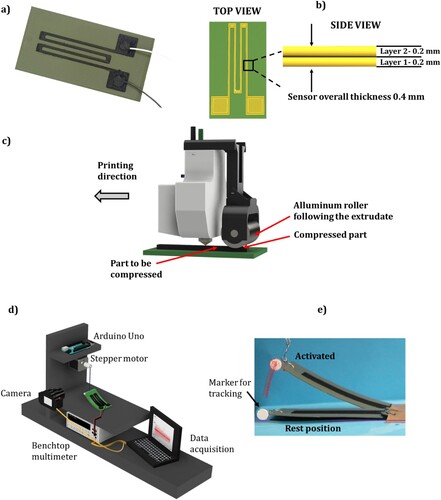
Table 1. Main process parameters set for the fabrication of the sensors, regardless of the printing strategy (as-is, ironing, roller).
The proposed sensor can be exploited to detect multiple stimuli, such as strain and force. Among all the possible ways to leverage 3D printed piezoresistive sensors, a growing interest is risen in the field of bending angle measurements [Citation48], especially to sense soft and bio-inspired robotic hands and grippers [Citation47,Citation49,Citation50]. 3D printed bending sensors meets the pressing requirement of soft robotics, making AM the leading manufacturing technology in such field. For this reason, the authors designed the proposed sensor to be employed as bending sensors, thus the sensitivity can be expressed as follows:
(1)
(1) where
(
) represents the change in electrical resistance, while
represents the corresponding change in bending angle (degree).
An increased sensitivity implies a sensor is capable of detecting small changes in bending angles, which is beneficial for many applications such as biomedical, robotics, structure monitoring, non-destructive tests [Citation28,Citation51–58]. In accordance with recent progress in scientific literature, the interlayer adhesion of consecutive extruded layers can be expressed as follows [Citation59]:
(2)
(2) where
is the strength developed due to the wetting, while
is the strength developed due to the diffusion. Improving interlayer adhesion could imply a reduction in the void content, in turn, providing a better path to the current to flow. As such, there are two primary mechanisms used herein to improve the interlayer adhesion and, in turn increase the interlayer adhesion: applying pressure on the extruded layer (to increase the wetting area) and increasing the temperature at the interface between two layers (to increase the polymer chain diffusion).
As a consequence of Equation (2), the authors decided to 3D print piezoresistive sensors under the following conditions:
As-is: the process parameters described in Tab.1 have been used for the CPLA. This reflects the printing condition commonly used in scientific literature for the fabrication of piezoresistive sensors and smart structures when employing MEX machines and conductive PLA [Citation44].
Roller: a metallic (aluminium) roller was added to the print head to immediately follow the just extruded conductive material and compress it (see (c)). The roller (wider than the nozzle tip) was assembled 3 cm behind the nozzle to allow the total compression of the extruded material. As shown in the scientific literature [Citation60–63], this kind of approach based on the increase of the wetting area involves a reduction of voids and an improvement of the mechanical properties of samples prepared via the MEX technique. The roller applied a force of 8.3 N to the sample (measured by using a commercial force sensor).
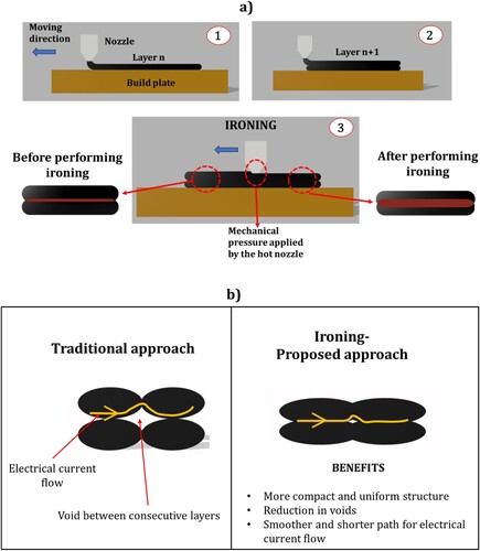
Ironing: it repeats the last extruded layer by passing the hot nozzle over it (see (a)). The last extruded layer is then compressed and heated up again. In this way, not only the wetted area is supposed to increase (due to the mechanical pressure applied by the nozzle), but also the polymer chain diffusion is supposed to improve since the last layer is locally heated up when the ironing is performed. The following parameters related to ironing have been set: pattern equal to zig-zag, line spacing equal to 0.05 mm, flow equal to 7%, ironing distance from the edge equal to 0.2 mm and nozzle temperature when performing ironing equal to 90°C. The ironing temperature was chosen with a trial-and-error approach, such that the temperature represents a compromise between the lower limit defined by the glass transition temperature (the ironing temperature has to be higher to improve the healing time) and the upper limit defined by the melting temperature (the ironing temperature has to be lower to avoid re-melting the material and significantly distorting the sample geometry).
Figure 2. (a) Step by step description of the ironing strategy and (b) mechanism underlying the better sensitivity achieved with the proposed approach based on the ironing strategy.
Three sensors for each printing condition have been manufactured and tested to consider the variability due to the additive manufacturing process. The effects of the printing strategies (i.e. as-is, roller and ironing) on the sensitivity of sensors have been analysed by employing a custom-made characterisation setup, shown in (d). Electrical wires have been soldered to the sensor pads and connected to a benchtop multimeter (GW Instek, GDM 8341), which in turn was connected to MATLAB (The Mathworks, Inc.) to record the resistance change throughout the whole test. The top part of the sensor was connected, by using nylon wire, to a stepper motor (NEMA 17) instructed through Arduino Uno. The stepper motor performs 13 cycles per minute; every cycle is composed of a forward movement followed by a backward movement, both performed at 300 RPM, which corresponds to a bending angle of the structure of 14.2 degree (see (e). The test was run for 6 min (78 cycles). A digital camera (Canon EOS 400D) was employed to record the test, and a white marker in the form of a pin was attached to the edge of the sensor to process the video through a video analysis and motion tracking open-source software (Tracker, OSP – Open Source Physic, USA) and obtain the bending angle of the sensor for every cycle (see (e)).
2.2. Microstructure evaluation
Two different microscopic studies have been performed to correlate the improvement in sensitivity with the internal microstructure in terms of voids reduction and improvement of the bond width. It is worth mentioning that both the microscopic evaluations have been performed, only considering ‘ironing’ and ‘as-is’ conditions since they respectively represent the best and worst results in terms of sensitivity (see Section 3.1). For this reason, the ‘roller’ condition was not considered.
CT scans were conducted using the NSI X-3000 X-Ray CT system (North Star Imaging, Microfocus) to analyse internal voids. A voltage of 50 kV and current of 700 µA and a focal spot size of 35 µm were employed for all scans, which was used to produce an X-ray beam with a voxel size of 15.82 µm. A reconstruction software, efX-CT, was employed following CT scan completion, wherein specific sharpness and beam hardening settings were selected for each scan in based on highlighting the void content within the printed material. After the reconstruction process, the data was analysed using Dragonfly’s segmentation wizard feature, which makes use of artificial intelligence (AI). The AI module of the software was trained to differentiate between voids (red), the material (yellow) and the background/air (blue) based on variations in greyscale values from the CT scan, as demonstrated in (a). Following the calibration of the AI feature, the software would autonomously identify similar greyscale values across all slices of the scanned sample, performing segmentation. The region of interest area (voids) is then analysed and calculated for each slice and plotted relative to the depth of the sample (as discussed in Section 3.2). Three ‘ironing’ and three ‘as-is’ samples were then analysed, and the results in terms of void reductions were correlated with the improved sensitivity, as detailed in Section 3.2. All the samples prepared for CT scans were composed of five beads (every bead was 0.8 mm wide, same dimension of the nozzle used to extrude CPLA) and five layers (every layer was 0.2 mm tall, same layer thickness set for throughout the whole research).
Figure 3. (a) User painted slice showcasing the three different features used to calculate porosity (void percentage) from X-Ray CT scans and (b) graphical representation of the bonding between two consecutive extruded layers.
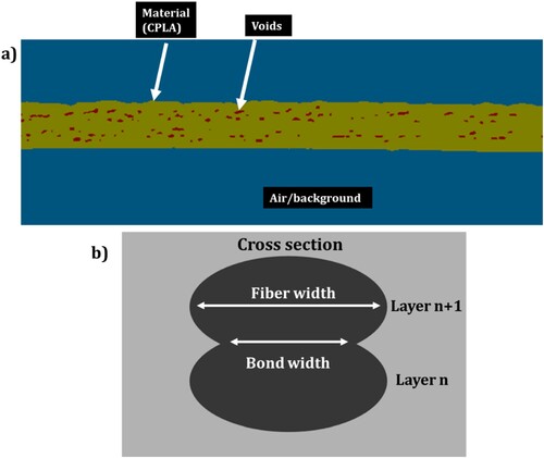
In addition to X-ray CT analysis, as the ironing strategy applies mechanical pressure to extruded layers, the micrscopic image analysis of sample cross sections were performed to verify if it was translated in an increased bond width. A Dino-Lite Edge 3.0 (Dunwell Tech Inc.; California, USA) digital microscope was used to calculate the wetting factor between consecutive layers, in accordance with Equation (3) proposed in [Citation59], as shown in Equation (3):
(3)
(3) where bond width (
) represents the contact length between layer
and layer
, and fibre width (
) represents the width of the single layer (theoretically, it should be equal to the nozzle diameter), as schematically represented in (b). A total of three CPLA test coupons (two beads, two layers) with and without performing ironing have been 3D printed. Each test coupon was sectioned every 5 mm using an IsoMet Low-Speed Saw (Buehler Ltd., Illinois, USA) to cut five small pieces and manually polished using 400, 600, 1000, 2000, 3000 grit sandpapers sequentially. For ease of cutting in the low-speed saw, each test coupon was cast in the PRO-SET INF-114 infusion resin and hardener (Gougeon Brothers, Inc. MI, USA) and was cured for 24 h in the room temperature. The low-speed saw was used at a low rotation per minute to avoid disturbing the test surface.
3. Results and discussion
3.1. Sensitivity improvement
The relationship between sensitivity and the three different extrusion strategies detailed in Section 2.2 (as-is, roller and ironing) has been studied by cyclically bending the sensor 78 times at a frequency of 0.002 Hz, as described in Section 2.1 and shown in (e). The main results are shown in , where the relative change in resistance versus time while bending the sensor has been plotted. Every test has been performed on three different samples for printing strategy, to consider the variability due to the manufacturing process, as well as the testing conditions. From the characterisation test, several conclusions can be drawn. First, the printing artefacts used in accordance with Equation (2) produce an increase in the sensitivity of the sensor. As shown in (a–c), there is a constant increase in the amplitude of
when switching from ‘as-is’ to ‘roller’ and from the latter to ‘ironing’. From (a–c) a slight change in the response of the sensor, (
) over time can be noted. As each graph represents the average behaviour of three identical sensors, the authors hypothesise that such change in the response might be due to the variability affecting the manufacturing process, as well as slight changes in the setup environment during the test (i.e. change of temperature and humidity). An overview of the direct correlation between change in resistance and bending angle, for the ‘ironing’ sample (cycles 52–57) is shown in d). It should be noted that the proposed characterisation method was consistent, as demonstrated in (e), in which a maximum bending angle of 14° and rest position angle of 2° was consistently achieved every cycle.
Figure 4. (a) Change in relative resistance vs time for as-is sensor, (b) change in relative resistance vs time for roller sensor, (c) change in relative resistance vs time for ironing, (d) Resistance vs bending angle for ‘ironing’ sample (cycles 52–57), e) bending angle of the sensor during the characterisation and (f) sensitivity for the three tested printing strategy: ironing produces the best result.
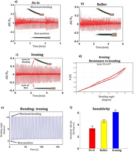
As shown in (f), the sensitivity of the ‘as-is’, ‘roller’ and ‘ironing’ sample is 3.35 , 4.64
and 6.12
, respectively. The best result is obtained when using the ironing strategy with an improvement of the sensitivity of 83% compared to the as-is sensor is. The standard deviation, calculated on three different samples was found to be lower than ±0.9
for each case. Additionally of note, while the effect wasn’t as marked as the ironing strategy, the roller strategy still produces an improvement of 39% in the sensitivity compared to the ‘as-is’ scenario.
Additional testing was conducted to further prove the benefit of the ironing strategy over the as-is printing scenario. The two versions of the sensor were tested under the same conditions (motor speed and number of cycles per minute) for 70 min. In this case, the raw data of resistance change (Ω) has been plotted as a function of the time without t normalising procedure. , which shows the performance of the ‘ironing’ sample, demonstrates that after approximately 30 min of testing, or a total of 390 bending cycles, a stabilisation in the resistance behaviour occurs when cyclically bending the sensor. Despite an initial drift behaviour of the sensor was observed for the first 30 min, stabilisation of the sensors response occurs for the remainder of the 70 min. The drift in resistance in 3D printed conductive polymer sensors is a very common issue that has been shown in literature. To date, no unified theory has been developed to explain this behaviour. While not validated, one proposed hypothesis from this work, and in accordance with scientific literature to date [Citation64–66], attributes the initial drift being related to Mullin’s effect which involves hysteresis and cyclic softening in plastic materials, as well as the viscoelastic effect. In accordance with the Mullins’ effect the majority of stress softening happens at the first cycles and sequenced cycles of stretching provoke the same or less stress softening [Citation67]. Another possible mechanism might be related to a change in temperature due to the flow of current inside a conductive material generating heat because of the Joule effect.
Figure 5. Long time bending test for ironing and as-is: stability after 30 min for ironing sample, and lack of stability for as-is sample.
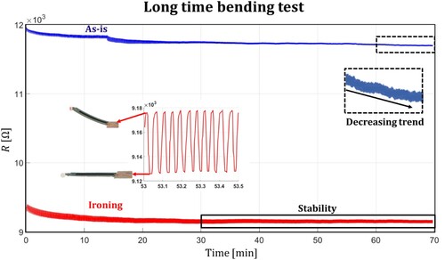
shows that when testing the as-is sample for 70 min, there is no stabilisation in the change of resistance, rather a constant decreasing drift in sensor response. To quantify the stability and the decreasing trend, the data from minute 30 up to minute 70, or the time window where the ironing sample showed great stability, have been fitted using a linear regression equation, obtaining respectively:
(4)
(4)
(5)
(5) EquationEquation (4)
(4)
(4) refers to the ironing sample, while EquationEquation (5)
(5)
(5) refers to the ‘as-is’ sample. The coefficient of determination,
, was found to be 0.96 and 0.89 respectively for the ironing (EquationEquation (4)
(4)
(4) , and as-is sample (EquationEquation (5)
(5)
(5) , showing that the linear regression model can be used to obtain useful insights about the stability of the proposed sensors. The slope of both curves is the metric used to evaluate the stability related to the change of electrical resistance. If the slope trends to zero (parallel to the x-axis) then the change in resistance of the sensor over time is stable. For the ironing scenario, the slope is
0.0002
, while as for the as-is scenario, the slope is two orders of magnitude higher at −0.07
. The following evaluation suggests how ironing contributed to making the sensor stable over time, unlike for the traditional as-is printing as observed in this work.
The improved stability can potentially be attributed to the ironing strategy, by reducing intralayer voids (as demonstrated in Section 3.2) and improving the healing time (as demonstrated in Section 3.3), resulting in a net improvement of the adhesion between the subsequently deposited layers. When cyclically stressed, a layered structure with weak adhesion (sensor ‘as-is’) could exhibit creep behaviour, resulting in a decreasing trend of the electrical resistance (). A detailed explanation of this phenomenon, which increases the stability, is provided in Section 3.3. Additionally, the ‘ironing’ sample was also tested at rest (without applying any bending) for a total of 60 min, in a controlled environment at 22 °C and no drift in the electrical resistance were recorded. This result is in accordance with the latest finding in scientific literature, where conductive polymer materials used for the fabrication of 3D printed sensors tend to have a strong correlation between electrical resistance and environmental temperature [Citation68–71]. It should be noted, if the proposed ‘ironing’ sensors is to be used in an environment with temperature fluctuations, the material coefficient of temperature (TC) has to be taken into account and compensation strategies need to be employed.
The ‘ironing’ sample was also cyclically tested to characterise its life span. A total of 10,000 bending cycles have been performed at a frequency of 0.002 Hz for a total of 12.82 h, and no damages were observed at the end of the test, suggesting that the proposed sensor can be employed for at least 10,000 cycles. The ironing sensor resolution and response time were also measured, resulting to be 1.2 degree and 60 .
In summary, the ironing strategy was shown to be the most suitable way to fabricate 3D printed piezoresistive sensors given the strategies attempted in this work, with the following benefits being achieved:
Sensitivity improvement of 83% compared to the traditional ‘as-is’ printing.
Less drift in sensor response after 30 min, the slope of −0.0002
‘ironed’ compared against −0.07
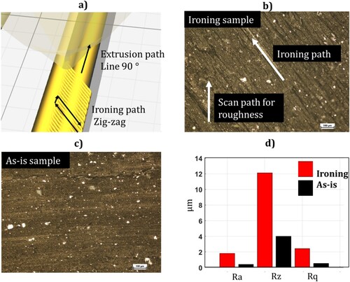
On one hand, the ironing strategy abruptly improves the sensitivity of 3D printed sensors, but on the other hand, it makes the strain gauge top surface less smooth compared to the ‘as-is’ traditional scenario. An industrial profilometer (Mitutoyo SJ-400) was employed to evaluate three different roughness values, namely ,
and
(in accordance with the international standard ISO 1302) Due to the ironing zig-zag path set in the slicing software, shown in (a,b), every roughness metric resulted to be increased compared to the traditional ‘as-is’ scenario, as shown in c). Five roughness measurements were taken for every sample with a scan path parallel to the beads, and a not statistically significant standard deviation (< 0.01 µm) was found. Therefore, the ironing process was fully characterised, demonstrating improvement in sensitivity at 83% results in a significant increase in surface roughness on the top of the strain gauge surface. It should be noted that this increase in surface roughness would make this approach infeasible for certain applications, such as additively manufactured optics and photonics [Citation72].
Figure 6. Roughnes evaluation: (a) Ironing path simulated into the slicing software, (b) Actual ironing path at microscope, (c) As-is sample at microscope and (d) Ra, Rz and Rq (ISO 1302) for ironing and as-is samples.
3.2. Relationship between ironing strategy and microstructural features
In this section, the improvement in sensitivity (described in Section 3.1) is deeply investigated from a microscopic standpoint, analysing the void volume fraction among conductive layers and proving that its reduction is strongly correlated to the improved performance of the sensor. All the tests have been conducted on ‘ironing’ (best sensitivity and stability) and ‘as-is’ samples (worst sensitivity and stability). A total of three identical samples for every scenario (‘as-is’ and ‘ironing’) have been manufactured and tested, to take into account the manufacturing variability affecting the MEX process.
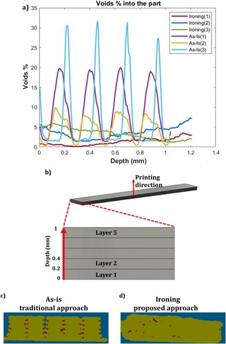
As described in Section 2.2, X-Ray CT scan tests were conducted to analyse the void volume percentage, also called porosity. As shown in (a), a great reduction in void content was achieved when employing the proposed ‘ironing’ approach, compared to the traditional ‘as-is’ scenario. (a) plots the porosity of three ‘as-is’ and three ‘ironing’ samples as a function of their depth, namely, the thickness of the samples. Every sample was composed of five layers, each one 0.2 mm thick. Depth equal to 0.2, 0.4, 0.6, 0.8 and 1 mm, respectively, refers to layers 1, 2, 3, 4 and 5 (see (b)). The primary outcomes from the CT scan analysis are listed here as:
For ‘as-is’ samples the void content was dependent on the location, or depth into the sample. At the interface between every layer (i.e. layer 2 at 0.4 mm, layer 3 at 0.6 mm and so on) a spike in void content occurs. In the ‘ironing’ samples, the void content is less dependent on the thickness, in which a constant value is recorded throughout the sample. This phenomena is driven by the underlying mechanisms that ironing uses, in which the hot nozzle applies mechanical pressure and thermal energy simultaneously, increasing the bond width between consecutive extruded layers and subsequently reduces the void content at the interface. The traditional printing scenario (‘as-is’) suffers from lower bond width, which is translated into void content spikes at the interface between consecutive layers.
The void content obtained when employed the proposed approach (ironing) resulted to be 2.8% with a standard deviation of 1.3, while the traditional ‘as-is’ scenario was characterised by a porosity of 6.9% with a standard deviation of 2.1. The proposed approach resulted in a reduction in the porosity of 59%. This finding supports the hypothesis that links the improved sensitivity (83%) to a reduction in void content. (c,d) show cross-sectional images that demonstrate the significant differences in microstructure that can be observed between these samples.
Figure 7. Porosity: (a) void content % vs depth (sensor thickness) for three ironing and three as-is samples, (b) graphical representation of the correlation between depth and layers, (c) CT scan figure showing the voids in the cross section of ‘as-is’ sample and (d) CT scan figure showing the voids in the cross section of an ‘ironing’ sample.
Further investigation has been conducted to correlate the increased sensitivity to microscopic features of the ‘ironing’ samples, by analysing the ratio between and
, as expressed in EquationEquation (3)
(3)
(3) . Ideally, the
of two consecutive layers should be equal to the
, resulting in a
value equal to 1. As shown in (a), there is a clear indication of interface and not complete bonding between the two layers (
is smaller than
), as expected from the ‘as-is’ test coupon. The
values for the five cut sections of the ‘as-is’ coupon are listed in . It is evident that there was no complete wetting between consecutive layers as the average
(0.83) was always lower than 1, which fully agrees with available literature [Citation59]. On the other hand, when performing ironing, there was no distinguishable interface between consecutive layers, indicating complete wetting at the interface. As a matter of fact, the
value, in this case, is considered as 1, indicating increased wetted area. Due to the significant porosity reduction provided by the ironing technique, the authors envision that custom-made nozzles designed to maximise the ironing performance in terms of interlayer adhesion could be fabricated and used to further leverage the ironing strategy.
Figure 8. Cross section view of as-is sample using digital microscope: bond width and fibre width are shown at the interface between consecutive extruded layers.
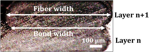
Table 2. Adhesion for ‘as-is’ samples in five different locations.
3.3. Relationship between ironing strategy and improved interlayer diffusion
One of the most important mechanisms accountable for layer-by-layer adhesion is the polymer chain diffusion at the interface between consecutive layers, where more polymer chain diffusion results in higher interfacial adhesion. As shown in Coogan and Kazmer [Citation60], the fraction of diffusion at the interface can be written as follows:
(6)
(6) where
(s) represents the total healing time, namely the time at which the diffusion occurs when
>
. The ironing strategy, as detailed in Section 2.2, is executed by passing the hot nozzle over the last extruded layer. The nozzle temperature was arbitrarily set to 90 °C, while performing ironing.
In this way, the last extruded conductive layer, that already cooled down under has been reheated above
, enabling further interlayer diffusion.
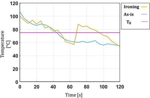
An experimental setup consisting of a FLIR A700 thermal camera capable of taking infrared (IR) videos was attached to a custom-made frame placed on the top of the machine (the camera lens was parallel to the building plate). All the analyses were performed by focusing on a single region of interest (1 pixel) located on the conductive track of the sensor. Videos were taken during the extrusion of the last conductive layer for a total of 120 s, under the two printing conditions studied in this research, namely ‘as-is’ and ‘ironing’. As shown in , for the ‘as-is’ scenario (traditional printing condition), the temperature of the extruded conductive material was above for a total of 44 s, from
up to
. Subsequently, the temperature never rose above
, as expected. The behaviour of the ‘ironing’ sample was fundamentally different, in which the temperature went below
after 48 s, but after performing ironing the temperature rose again above
, from
up to
, for a total of an additional 29 s after ironing was completed. By summarising, the total healing time
, namely the amount of time above T glass, for the ironed sample was 77 s against 44 s for the as-is sample, as shown in .
Figure 9. Temperature history profile for ironing, and as-is samples during fabrication with respect to CPLA glass transition (Tg) temperature.
It should be noted that, while performing ironing, the two most important process parameters accountable for increasing the layer temperature above are i) the temperature of the hot nozzle while performing ironing (set to 90°C in this work) and, ii) the ironing speed, namely the speed at which the hot nozzle moves on the last extruded layer (set to 10 mm/s in this work), in that a lower speed results in more heat exchanged with the conductive layer.
This outcome suggests that in the case of ironing, a higher diffusion at the layer interfaces occurs since the healing time (), namely the time every layer is above
, is higher compared to the traditional as-is scenario. As demonstrated in [Citation60],
is a crucial variable to bond (heal) two consecutive layers of polymeric material processed via the MEX approach.
represents the time at which the diffusion between two layers occur: the higher
, the higher the intralayer adhesion. As such, higher interface diffusion is translated into better adhesion and, in turn, better mechanical properties. It is hypothesised that this phenomenon could be the underlying mechanism driving the improved great stability recorded for the ironed samples. Additionally of note, as the layer adhesion is improved, common problems in layered structures such as delamination and creeping were reduced, resulting in enhanced stability of electrical resistance variation when 3D printed sensors are cyclically stressed.
4. Proposed approach for smart structures
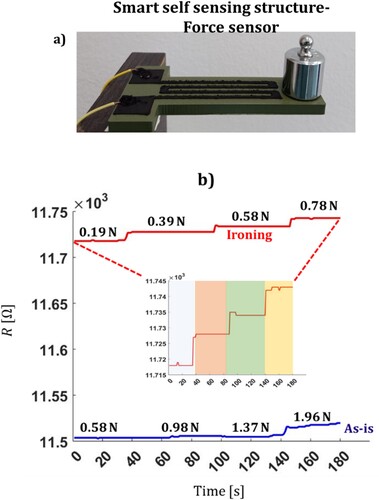
The proposed approach based on the usage of the ironing strategy to improve sensor performance has been used for the fabrication of two proof of concept smart 3D printed devices: a smart self-monitoring structure and a smart auxetic structure. In both cases, the dielectric structure and the conductive sensors have been 3D printed in the same manufacturing cycle, resulting in no assembly steps. A simple prismatic PLA smart structure was manufactured by depositing a piezoresistive sensor onto the main structure to create a force sensor capable of detecting the applied force, as shown in (a). Two self-monitoring structures were fabricated, respectively, by employing the approach proposed in the present research (ironing) and by using regular printing settings (as-is). Several calibrated weights have been applied on the top of the smart structure (see (a)) and the change in electrical resistance of the sensor was recorded using the same benchtop multimeter described in Section 2.1. From (b), the proposed benefits from the phenomena displayed in this work demonstrate the potential performance increase that can be seen in 3D printed smart structures that employ piezoresistive sensors. The smart structures printed using the ironing approach are capable of detecting a minimum change of force of 0.19 N due to their improved sensitivity as compared to their traditionally printed counterpart. The structure fabricated under traditional printing conditions (as-is) shows a very low sensitivity with a minimum force detection of 1.96 N. Due to the increased sensitivity, the proposed approach could be used to 3D printed structural components undergoing loads to obtain real-time data about the applied force. Another potential use of the proposed approach is related to structural health monitoring in which structural plastic components difficult to be inspected with traditional approaches could be monolithically fabricated with embedded piezoresistive sensors, and the change in electrical resistances could be associated to potential damages in the structure.
Figure 10. (a) 3D printed smart self sensing device (green = PLA, black = CPLA), (b) Response of the structure fabricated using the traditional and proposed approach.
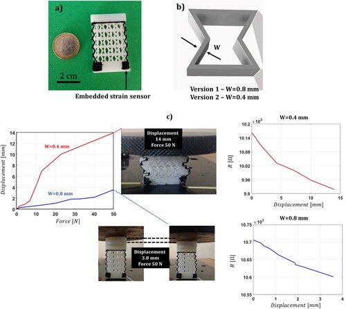
Finally, an auxetic structure (geometry proposed in [Citation73]) was 3D printed with an embedded sensor. In this case, the embedded sensor fabricated by using the proposed adhesion-centered approach, was employed to sense displacement, as opposed of bending (the focus of Sections 2and 3), showing the wide range of possible applications of 3D printed piezoresistive sensors. The dielectric component of the auxetic device was fabricated by employing thermoplastic polyurethane (TPU), one of the most common soft materials for auxetic devices. The smart auxetic structure is shown in (a), with two different versions have been created. The first version having the walls of the unit cell (see (b)) equal to 0.8 mm, and a second version with walls of 0.4 mm. A dual-track piezoresistive sensor was fabricated on the top of the TPU auxetic geometry for both version. The reason for manufacturing two versions of the same auxetic structures is to prove the scalability in terms of sensor width of the proposed approach. For both versions, the ironing strategy was used to enhance the sensitivity. Both versions have been tested by employing an Instron 68TM-10 machine to compress the auxetic structures, while the force, displacement and electrical resistance of the sensor were simultaneously recorded. A maximum force of 50 N was applied. Version one with walls of 0.8 mm exhibited a maximum displacement of 3.8 mm, while version two with walls of 0.4 mm exhibited a maximum displacement of 14 mm. For both versions, a decrease in resistance occurred while compressing the auxetic device, as expected from the piezoresistive theory. In this case, the change in resistance was correlated to the displacement of the auxetic structure, and for version two (the one exhibiting the highest displacement), a sensitivity of 17.6 was obtained. The same auxetic structure having a wall thickness of 0.4 mm (the one exhibiting a larger displacement) was also fabricated without applying ‘ironing’ on the top surface of the sensor, namely according to the ‘as-is’ scenario. While testing the structure, a delamination of conductive layers of the sensors occurred at a force of 12 N (displacement of 4.75 mm) making the ‘as-is’ strategy unsuitable for the fabrication of smart auxetic structures undergoing an appreciable amount of compression. Such outcomes are directly correlated to the findings of Section 3.2, and 3.3. By leveraging the ironing strategy, a great interlayer adhesion occurs, demonstrated by a void reduction of 59% and an increased healing time (from 44s to 77s).
Figure 11. (a) 3D printed smart auxetic device, (b) different thickness of the unit cell, (c) characterisation of the two versions of the auxetic device.
Auxetic structures have been gaining a lot of popularity since they can efficiently absorb huge amounts of energy and provide several benefits to many fields such as military, biomedical and sport [Citation74–76]. A lack of scientific literature about auxetic devices with embedded sensors motivated the authors to fabricate TPU auxetic shapes with embedded piezoresistive sensors using a monolithic approach. In this way, inexpensive auxetic devices could provide the users additional benefits, such as real-time data related to the displacement of the whole structure, as shown herein, and potentially to the applied force and energy absorbed from the auxetic structure.
5. Conclusions
The work herein highlights the significance to which the ironing strategy can be used in the fabrication of MEX sensors and smart structures. This very simple and effective method was used to enhance the electrical properties of 3D printed sensors. The ironing strategy does not require any 3D printing machine modifications since it leverages the hot nozzle to ‘iron’ the previously extruded layer of CPLA by making the structure compact and uniform via the application of heat and mechanical pressure. The ironing process parameter increased the sensitivity of 3D printed sensor by 83% due in part to the mechanical pressure applied from the hot nozzle reduces the voids among consecutive layers. The reduction of voids has been analysed by using an X-Ray CT scan system, and a porosity reduction of 59% was achieved when performing ironing compared to the traditional as-is printing scenario. Ironed samples also show an increased bond width between consecutive layers almost equal to the fibre width, resulting in an improved wetting factor. The reduction in voids provides a smoother path for electrical current flow. The macroscopic findings, such as higher sensitivity, have been then related to the improved microscopic features, such as decreased void content, of the 3D printed sensors. Lastly, the ironing process parameter was found to improve the stability of electrical resistance when stressing the sensor cyclically. When performing ironing, the hot nozzle heats up the previously extruded layer above its glass transition () temperature, resulting in an increased healing time (
) of the layer. The increased
means increased polymer chain diffusion, which, in conjunction with the reduction of voids, promotes improvement interlayer adhesion. For this reason, the ironed sample presents good stability in the electrical resistance when mechanically stressed. In conclusion, the ironing parameter could be potentially used every time 3D printed sensors are fabricated via MEX systems to improve their electrical performance without recurring any post-treatments and machine modifications. Future works will be focusing on modelling the sensor performance (i.e. stability) by combining several variables, such as intralayer voids, noise and variability. The main findings of the research are listed in .
Table 3. Main outcomes presented in this research work.
Disclosure statement
No potential conflict of interest was reported by the author(s).
Funding
The following research work was supported by the following funding sources:
BRIEF – Biorobotics Research and Innovation Engineering Facilities – Missione 4, ‘Istruzione e Ricerca' – Componente 2, ‘Dalla ricerca all'impresa' – Linea di investimento 3.1, ‘Fondo per la realizzazione di un sistema integrato di infrastrutture di ricerca e innovazione’, funded by European Union – NextGenerationEU, CUP: J13C22000400007.
European Union Framework Programme for Research and Innovation – National Recovery and Resilience Plan (NRRP), Mission 4 Component 2 Investment 1.3 – Call for tender No. 341 of 15/03/2022 of Italian Ministry of University and Research funded by the European Union – Next Generation EU. Award Number: PE00000004, Concession Decree No. 1551 of 11/10/2022 adopted by the Italian Ministry of University and Research, CUP D93C22000920001, MICS (Made in Italy – Circular and Sustainable).
Data availability statement
Data will be made available upon request to the corresponding author.
References
- Lussenburg K, Sakes A, Breedveld P. Design of non-assembly mechanisms: A state-of-the-art review. Addit Manuf. 2021;39(May 2020):101846. doi:10.1016/j.addma.2021.101846
- Cuellar JS, Smit G, Plettenburg D, et al. Additive manufacturing of non-assembly mechanisms. Addit Manuf. 2018;21(January):150–158. doi:10.1016/j.addma.2018.02.004
- Yin J, Lu C, Fu J, et al. Interfacial bonding during multi-material fused deposition modeling (FDM) process due to inter-molecular diffusion. Mater Des. 2018;150:104–112. doi:10.1016/j.matdes.2018.04.029
- Tamburrino F, Graziosi S, Bordegoni M. The influence of slicing parameters on the multi-material adhesion mechanisms of FDM printed parts: an exploratory study. Virtual Phys Prototyp. 2019;14(4):316–322. doi:10.1080/17452759.2019.1607758
- Lopes LR, Silva AF, Carneiro OS. Multi-material 3D printing: The relevance of materials affinity on the boundary interface performance. Addit Manuf. 2018;23(March):45–52. doi:10.1016/j.addma.2018.06.027
- Khudiakova A, Arbeiter F, Spoerk M, et al. Inter-layer bonding characterisation between materials with different degrees of stiffness processed by fused filament fabrication. Addit Manuf. 2019;28(March):184–193. doi: 10.1016/j.addma.2019.05.006.
- Altuntas U, Coker D, Yavas D. Creating tougher interfaces via suture morphology in 3D-printed multi-material polymer composites by fused filament fabrication. Addit Manuf. 2023;61(November 2022):103359. doi:10.1016/j.addma.2022.103359
- Stano G, Ovy SMAI, Percoco G, et al. Additive manufacturing for bioinspired structures: experimental study to improve the multimaterial adhesion between soft and stiff materials. 3D Print Addit Manuf 2023;1080–1089. doi:10.1089/3dp.2022.0186
- Goh GL, Zhang H, Chong TH, et al. 3D printing of multilayered and multimaterial electronics: a review. Adv Electron Mater. 2021;7(10):1–28. doi:10.1002/aelm.202100445
- Emon MOF, Alkadi F, Philip DG, et al. Multi-material 3D printing of a soft pressure sensor. Addit Manuf. 2019;28(May):629–638. doi:10.1016/j.addma.2019.06.001
- Košir T, Slavič J. Manufacturing of single-process 3D-printed piezoelectric sensors with electromagnetic protection using thermoplastic material extrusion. Addit Manuf. 2023;73(June):103699. doi:10.1016/j.addma.2023.103699
- Košir T, Slavič J. Single-process fused filament fabrication 3D-printed high-sensitivity dynamic piezoelectric sensor. Addit Manuf. 2022;49(June 2021):102482. doi:10.1016/j.addma.2021.102482
- Loh LYW, Gupta U, Wang Y, et al. 3D printed metamaterial capacitive sensing array for universal jamming gripper and human joint wearables. Adv Eng Mater. 2021;23(5):1–9. doi:10.1002/adem.202001082
- Blaž N, Kisić M, Živanov L, et al. Capacitive sensor with stretchable membrane fabricated by 3D printing for displacement application. EUROCON 2019 - 18th Int. Conf. Smart Technol., p. 6–10, 2019. doi:10.1109/EUROCON.2019.8861960
- Oprel J, Wolterink G, Schilder J, et al. Novel 3D printed capacitive shear stress sensor. Addit Manuf. 2023;73(June):103674. doi:10.1016/j.addma.2023.103674
- Dijkshoorn A, Werkman P, Welleweerd M, et al. Embedded sensing: integrating sensors in 3-D printed structures. J Sensors Sens Syst. 2018;7(1):169–181. doi:10.5194/jsss-7-169-2018
- Schouten M, Wolterink G, Dijkshoorn A, et al. A review of extrusion-based 3D printing for the fabrication of electro- and biomechanical sensors. IEEE Sens J. 2021;21(11):12900–12912. doi:10.1109/JSEN.2020.3042436
- Banks JD, Emami A. Carbon-based piezoresistive polymer nanocomposites by extrusion additive manufacturing: process, material design, and current progress. 3D Print. Addit. Manuf., Dec. 2022. doi:10.1089/3dp.2022.0153
- Tan JC, Low HY. Embedded electrical tracks in 3D printed objects by fused filament fabrication of highly conductive composites. Addit Manuf. 2018;23(April):294–302. doi:10.1016/j.addma.2018.06.009
- Lazarus N, Tyler JB, Cardenas JA, et al. Direct electroless plating of conductive thermoplastics for selective metallization of 3D printed parts. Addit Manuf. 2022;55(March):102793. doi:10.1016/j.addma.2022.102793
- Tan JC, Low HY. Multi-materials fused filament printing with embedded highly conductive suspended structures for compressive sensing. Addit Manuf. 2020;36(May):101551. doi:10.1016/j.addma.2020.101551
- Urra Sanchez O, Besharatloo H, Yus J, et al. Material thermal extrusion of conductive 3D electrodes using highly loaded graphene and graphite colloidal feedstock. Addit Manuf. 2023;72(June):103643. doi:10.1016/j.addma.2023.103643
- Li T, Saadatnia Z, Chen T, et al. Facile material extrusion of 3D wearable conductive-polymer micro-super-capacitors. Addit Manuf. 2023;74(July):103714. doi:10.1016/j.addma.2023.103714
- Potnuru A, Tadesse Y. Investigation of polylactide and carbon nanocomposite filament for 3D printing. Prog Addit Manuf. 2019;4(1):23–41. doi:10.1007/s40964-018-0057-z
- Podsiadły B, Skalski A, Wałpuski B, et al. Heterophase materials for fused filament fabrication of structural electronics. J Mater Sci Mater Electron. 2019;30(2):1236–1245. doi:10.1007/s10854-018-0391-4
- Wang Z, Wu Y, Zhu B, et al. A magnetic soft robot with multimodal sensing capability by multimaterial direct ink writing. Addit Manuf. 2023;61(November 2022):103320. doi:10.1016/j.addma.2022.103320
- Goh GL, Yeong WY, Altherr J, et al. 3D printing of soft sensors for soft gripper applications. Mater Today Proc. 2022;70:224–229. doi:10.1016/j.matpr.2022.09.025
- Stano G, Ovy SMAI, Edwards JR, et al. One-shot additive manufacturing of robotic finger with embedded sensing and actuation. Int J Adv Manuf Technol. 2023;124(1–2):467–485. doi:10.1007/s00170-022-10556-x
- Singh D, Tawk C, Mutlu R, et al. A 3D printed soft force sensor for soft haptics. 2020 3rd IEEE Int. Conf. Soft Robot. RoboSoft 2020, p. 458–463, 2020. doi:10.1109/RoboSoft48309.2020.9115991
- Singh Matharu P, Wang Z, Costello JH, et al. Sojel –A 3D printed jellyfish-like robot using soft materials for underwater applications. Ocean Eng. 2023;279(April):114427. doi:10.1016/j.oceaneng.2023.114427
- Maurizi M, Slavic J, Cianetti F, et al. Dynamic measurements using FDM 3D-printed embedded strain sensors. Sensors (Switzerland). 2019;19(12):1–15. doi:10.3390/s19122661
- Arh M, Slavič J, Boltežar M. Experimental identification of the dynamic piezoresistivity of fused-filament-fabricated structures. Addit Manuf. 2020;36(April):101493. doi:10.1016/j.addma.2020.101493
- Hohimer CJ, Petrossian G, Ameli A, et al. 3D printed conductive thermoplastic polyurethane/carbon nanotube composites for capacitive and piezoresistive sensing in soft pneumatic actuators. Addit Manuf. 2020;34(April):101281. doi:10.1016/j.addma.2020.101281
- Lalegani Dezaki M, Sales R, Zolfagharian A, et al. Soft pneumatic actuators with integrated resistive sensors enabled by multi-material 3D printing. Int J Adv Manuf Technol. 2023;128(9–10):4207–4221. doi:10.1007/s00170-023-12181-8
- Georgopoulou A, Egloff L, Vanderborght B, et al. A sensorized soft pneumatic actuator fabricated with extrusion-based additive manufacturing. Actuators. 2021;10(5):102. doi:10.3390/act10050102
- Mousavi S, Howard D, Zhang F, et al. Direct 3D printing of highly anisotropic,: flexible, constriction-resistive sensors for multidirectional proprioception in soft robots. ACS Appl Mater Interfaces. 2020;12(13):15631–15643. doi:10.1021/acsami.9b21816
- Leigh SJ, Bradley RJ, Purssell CP, et al. A simple, Low-cost conductive composite material for 3D printing of electronic sensors. PLoS One. 2012;7(11):1–6. doi:10.1371/journal.pone.0049365
- Yang Y, Chen Y, Li Y, et al. Novel variable-stiffness robotic fingers with built-In position feedback. Soft Robot. 2017;4(4):338–352. doi:10.1089/soro.2016.0060
- Ji Q, Jansson J, Sjöberg M, et al. Design and calibration of 3D printed soft deformation sensors for soft actuator control. Mechatronics (Oxf). 2023;92(February):102980. doi:10.1016/j.mechatronics.2023.102980
- Grønborg F, Zsurzsan TG, Daugaard AE, et al. Conductive compliant mechanisms: geometric tuning of 3D printed flexural sensors. Addit Manuf Lett. 2022;3(September):100088. doi:10.1016/j.addlet.2022.100088
- Li B, Zhang S, Zhang L, et al. Strain sensing behavior of FDM 3D printed carbon black filled TPU with periodic configurations and flexible substrates. J Manuf Process. 2022;74(November 2021):283–295. doi:10.1016/j.jmapro.2021.12.020
- Yu R, Xia T, Wu B, et al. Highly sensitive flexible piezoresistive sensor with 3D conductive network. ACS Applied Materials and Interfaces. 2020;12(31):35291–35299. doi:10.1021/acsami.0c09552
- Kwon SN, Kim SW, Kim IG, et al. Direct 3D printing of graphene nanoplatelet/silver nanoparticle-based nanocomposites for multiaxial piezoresistive sensor applications. Adv Mater Technol. 2019;4(2):1–9. doi:10.1002/admt.201800500
- Dembek K, Podsiadły B, Słoma M. Influence of process parameters on the resistivity of 3D printed electrically conductive structures. Micromachines (Basel). 2022;13(8). doi:10.3390/mi13081203
- Stano G, Di Nisio A, Lanzolla AM, et al. Fused filament fabrication of commercial conductive filaments : experimental study on the process parameters aimed at the minimization, repeatability and thermal characterization of electrical resistance. Int J Adv Manuf Technol. 2020;111:2971–2986.
- Palmić TB, Slavič J, Boltežar M. Process parameters for FFF 3D-printed conductors for applications in sensors. Sensors (Switzerland. 2020;20(16):1–21. doi:10.3390/s20164542
- Goh G, Goh G, Nguyen V, et al. A 3D printing-enabled artificially innervated smart soft gripper with variable joint stiffness. Adv Mater Technol. 2023;2301426:1–15. doi:10.1002/admt.202301426
- Nassar H, Ntagios M, Navaraj WT, et al. Multi-material 3D printed bendable smart sensing structures. p. 12–15, 2018. doi:10.1109/ICSENS.2018.8589625
- Zolfagharian A, Mahmud MAP, Gharaie S, et al. 3D/4D-printed bending-type soft pneumatic actuators: fabrication,: modelling, and control. Virtual Phys Prototyp. 2020;15(4):373–402. doi:10.1080/17452759.2020.1795209
- Nassar H, Ntagios M, Navaraj WT, et al. Multi-material 3D printed bendable smart sensing structures. In: 2018 IEEE sensors. New Delhi; 2018. p. 1–4. doi:10.1109/ICSENS.2018.8589625
- Teng K, Kot P, Muradov M, et al. Embedded smart antenna for non-destructive testing and evaluation (NDT&E) of moisture content and deterioration in concrete. Sensors (Switzerland). 2019;19(3). doi:10.3390/s19030547
- Ali MA, Hu C, Yttri EA, et al. Recent advances in 3D printing of biomedical sensing devices. Adv Funct Mater. 2022;32(9):2107671. doi:10.1002/adfm.202107671
- Tawk C, Alici G. A review of 3D-printable soft pneumatic actuators and sensors: research challenges and opportunities. Adv Intell Syst. 2021;3(6):2000223. doi:10.1002/aisy.202000223
- Mashayekhi F, Bardon J, Koutsawa Y, et al. Methods for embedding fiber Bragg grating sensors during material extrusion: relationship between the interfacial bonding and strain transfer. Addit Manuf. 2023;68(December 2022):103497. doi:10.1016/j.addma.2023.103497
- Palmieri M, Slavič J, Cianetti F. Single-process 3D-printed structures with vibration durability self-awareness. Addit Manuf. 2021;47(May):102303. doi:10.1016/j.addma.2021.102303
- Billah KMM, Coronel JL, Chavez L, et al. Additive manufacturing of multimaterial and multifunctional -structures via ultrasonic embedding of continuous carbon fiber. Compos Part C Open Access. 2021;5(April):100149. doi:10.1016/j.jcomc.2021.100149
- MacDonald E, Wicker R. Multiprocess 3D printing for increasing component functionality. Science (80-). 2016;353(6307). doi:10.1126/science.aaf2093
- MacDonald E, et al. 3D printing for the rapid prototyping of structural electronics. IEEE Access. 2014;2:234–242. doi:10.1109/ACCESS.2014.2311810
- Coogan TJ, Kazmer DO. Healing simulation for bond strength prediction of FDM. Rapid Prototyp J. 2017;23(3):551–561. doi:10.1108/RPJ-03-2016-0051
- Coogan TJ, Kazmer DO. Prediction of interlayer strength in material extrusion additive manufacturing. Addit Manuf. 2020;35(June):101368. doi:10.1016/j.addma.2020.101368
- Sayah N, Smith DE. Effect of process parameters on void distribution, volume fraction, and sphericity within the bead microstructure of large-area additive manufacturing polymer composites. Polymers (Basel). 2022;14(23)., doi:10.3390/polym14235107
- Andreu A, Kim S, Dittus J, et al. Hybrid material extrusion 3D printing to strengthen interlayer adhesion through hot rolling. Addit Manuf. 2022;55(March):1–9. doi:10.1016/j.addma.2022.102773
- Qasaimeh M, Ravoori D, Jain A, et al. Modeling the effect of In situ nozzle-integrated compression rolling on the void reduction and filaments-filament adhesion in fused filament fabrication (FFF). Multiscale Sci Eng. 2022;4(1–2):37–54. doi:10.1007/s42493-022-00073-0
- Christ JF, Aliheidari N, Pötschke P, et al. Bidirectional and stretchable piezoresistive sensors enabled by multimaterial 3D printing of carbon nanotube/thermoplastic polyurethane nanocomposites. Polymers (Basel). 2018;11(1). doi:10.3390/polym11010011
- Xiang D, Zhang X, Li Y, et al. Enhanced performance of 3D printed highly elastic strain sensors of carbon nanotube/thermoplastic polyurethane nanocomposites via non-covalent interactions. Compos Part B Eng. 2019;176(May):107250. doi:10.1016/j.compositesb.2019.107250
- Christ JF, Aliheidari N, Ameli A, et al. 3D printed highly elastic strain sensors of multiwalled carbon nanotube/thermoplastic polyurethane nanocomposites. Mater Des. 2017;131:394–401. doi:10.1016/j.matdes.2017.06.011
- Diani J, Fayolle B, Gilormini P. A review on the Mullins effect. Eur Polym J. 2009;45(3):601–612. doi:10.1016/j.eurpolymj.2008.11.017
- Lanzolla AML, Attivissimo F, Percoco G, et al. Additive manufacturing for sensors: piezoresistive strain gauge with temperature compensation. Appl Sci. 2022;12(17). doi:10.3390/app12178607
- Stano G, Di Nisio A, Lanzolla AM, et al. Fused filament fabrication of commercial conductive filaments: experimental study on the process parameters aimed at the minimization,: repeatability and thermal characterization of electrical resistance. Int J Adv Manuf Technol. 2020;111(9): 2971–2986. doi:10.1007/s00170-020-06318-2
- Daniel F, Patoary NH, Moore AL, et al. Temperature-dependent electrical resistance of conductive polylactic acid filament for fused deposition modeling. Int J Adv Manuf Technol. Nov. 2018;99(5–8):1215–1224. doi:10.1007/s00170-018-2490-z
- Mohiuddin M, Hoa SV. Temperature dependent electrical conductivity of CNT-PEEK composites. Compos Sci Technol. Dec. 2011;72(1):21–27. doi:10.1016/j.compscitech.2011.08.018
- Gao H, An J, Chua CK, et al. 3D printed optics and photonics: processes,: materials and applications. Mater Today. Oct 2023;69:107–132. doi:10.1016/j.mattod.2023.06.019
- Chow L, Yick K, Wong K, et al. 3D printing auxetic architectures for hypertrophic scar therapy. Macromol Mater Eng. 2022;307(5):2100866. doi:10.1002/mame.202100866
- Zhang J, Lu G, You Z. Large deformation and energy absorption of additively manufactured auxetic materials and structures: A review. Compos Part B Eng. 2020;201(April):108340. doi:10.1016/j.compositesb.2020.108340
- Johnston R, Kazancı Z. Analysis of additively manufactured (3D printed) dual-material auxetic structures under compression. Addit Manuf. 2021;38(November 2020):101783. doi:10.1016/j.addma.2020.101783
- Günaydın K, Rea C, Kazancı Z. Energy absorption enhancement of additively manufactured hexagonal and re-entrant (auxetic) lattice structures by using multi-material reinforcements. Addit Manuf. 2022;59(PA):103076. doi:10.1016/j.addma.2022.103076